1 VSB-Technical University of Ostrava, ENET Centre, 17. listopadu 15/2172, 708 33 Ostrava-Poruba, Czech Republic, e-mail: david.zurovec@vsb.cz
2 DSD-Dostal, a.s., Bystricka 38, 751 14 Drevohostice, Czech Republic
ABSTRACT
This article addresses the optimization of a dosing tank using a spiral harmonic mo-tion. The dosing tank is used for ashort-term storage of cohesive sand, which is then released into a tubular mold. Originally, a solution based on the principle of wiping
the material using rotary blades and brushes was used to fill the molds. However, this method was not effective enough. This solution suffered from uneven dosing as well as a loss of material. The mold filling time ranged around 20 seconds. During the
course of optimization of the dosing tank, a new design of the tank was created and external energy in aform of harmonic spiral vibrations was introduced into the sys-tem. The chosen shape of the harmonic spiral motion proved to be the most suitable for continuous emptying of the cohesive sand from the dosing tank into the tubular
mold in a very short time. There was also a significant elimination of material losses. It was determined that the frequency of harmonic motion affects uniform dispensing
of material fromtanks.
Keywords: spiral vibration, dosing tank, cohesive sand.
INTRODUCTION
Industrial enterprises are forced to invest in the development of technology due to techno-logical advances in all disciplines of mechani-cal engineering and ever-increasing demands for speedy manufacturing processes.When designing transport and storage facilities, it is appropriate to use studies and knowledge from various areas of transport and handling equipment designed
not only for bulk materials [1, 2, 3]. The present
study addresses the optimization of emptying a dosing device designed for the short-term storage of an exact amount of cohesive sand. In general, storage facilities such as tanks or silos are used to hold loose material in a closed space for the necessary amount of time. The construction of the storage facilities is dimensioned according to the required storage time as well as the mechanical and physical properties of the stored bulk
mate-rials. Mechanical and physical properties signifi
-cantly influence the behavior of bulk materials in storage processes [4, 5, 6]. In fact, negative
behaviour such as vaulting are not uncommon during emptying tanks. The optimal emptying of tanks requires knowledge of the operating con-ditions and detailed information about the stored material. This above all includes the aforemen-tioned mechanical and physical properties of the stored material, the shape and size of the tank, the hopper and the discharge opening. In terms of the nature of the tank emptying, we distinguish two
ways of material flow: mass and core flow. Mass flow is manifested by the gradual draining of ma -terial from the tank in order, in which it was intro-duced to the tank. To achieve this, an optimal con-struction design of the storage device is required depending on the properties of the stored material
[7]. However, in reality this is often not achieved,
and it requires the use of external sources of
ergy, such as vibrations, acoustic waves or air
[8, 9, 10]. The core flow is characterized by the principle that the material loaded inthe tank first, discharges last. Here, the material above the dis
-charge opening is dis-charged first and the material
adjacent to the walls of the tank remains still, cre-ating so-called “dead zones”. The material locat-ed in such “dead zones” often adheres to the walls of the tank due to longer static persistence, which
is perceived as a failure state [11, 12]. Other fail -ure states including static vaults, cavities or tun-nels may also occur in storage devices, which all
negatively affect continuous emptying. However,
the advancement of technology provides methods
such as the Discrete Element Method (DEM),
to detect and monitor failure states in transport and storage facilities. The advantage of using the
DEM simulation method lies in software verifi -cation of planned changes in design of a device
being developed or optimized [13, 14].
DESCRIPTION OF THE CURRENT
TECHNOLOGICAL PROCESS
During the course of this research, an analysis
of the current technology of sand dosing into tu-bular molds was performed. The technology was developed many years ago and it no longer meets today’s requirements. The existing technology is based on the principle of wiping sand with a total dose weight of 4 kg into a tubular mold using ro-tary blades and brushes located in a cubical dosing tank. Fig. 1 summarizes the dosing method into
three steps: I, II, III. In the first step (I), the dos -ing tank arrives above the pair of open-ings of the tubular mold and the discharge outlet is opened. In
the second step (II), the process of material wip -ing us-ing a system of rotary blades and brushes is initialized. This process takes place for almost 15
seconds. In the third step (III), the dosing tank re
-turns to the filling area to start a new filling cycle. During the filling of the dosing tank, the tubular mold is prepared for the next filling cycle.
However, this method was not effective
enough as it often resulted in uneven dosing and
material loss, as shown in Fig. 1 in steps (I) and (III). Furthermore, the mold filling time was no longer sufficient to meet current requirements
and it was necessary to proceed to a comprehen-sive optimization of the process. The aim of the
optimization was to ensure a uniform filling of
the tubular mold to eliminate material losses as
well as decrease the filling time by two-thirds. In the first step of the optimization, the current
state was evaluated while the mechanical and physical characteristics of the sand were mea-sured. Based on the data collected about the pro-cess and the bulk material used, the optimization
direction was determined. During the course of
optimization of the dosing tank, a new design of the tank was created and external energy in aform of harmonic spiral vibrations was intro-duced into the system.
Fig. 1. The principle of dosing cohesive sand into tubular molds [15]
Angle of internal friction φe
The angle of internal friction φe characterizes
flow properties of bulk materials. This includes
movements, resistances and bonds between indi-vidual particles. The angle of internal friction de-termines the shear properties of the mass, which
define the flowability of the sample being exam -ined. The angle of internal friction was measured
using aring shear tester Schulze RST-01. Fig. 3
shows the results ofmeasuring the angle of
inter-nal friction of the sand (φe = 43°). The dependence of normal stress σ on shear stress τ is shown as
well. Based on the measured values of the angle of internal friction of the sand, it was necessary to provide more energy to overcome the inter-parti-cle bonds and resistances.
Wall friction angle ϕw
The measurement of the wall friction angle was performed on the Jenike direct shear tester. The measurement principle consists of measuring
the time dependence of the shear stress τ, which
is required to shift bulk material over the contact
material, while gradually increasing normal stress
σ. The following contact materials were used: A) stainless steel sheet; B) Murtfeldtstandard “S” plastic; C) polyurethane. The results of measured values of wall friction angle ϕw and the wall
fric-tion coefficient μw are summarized in a single graph, which is shown in Fig. 4. From a compari-son of the results of external friction measured on individual contact materials, it is seen that the stainless-steel sheet exhibited the lowest resis-tance to movement.
Angle of repose Ψs
The angle of repose was measured using a measuring stand consisting of a steel bowl on which the material was gradually fed through a vibratory feeder. The bowl was placed on a rotary stand that allowed the pile to be monitored from
0° to 360°. The numerical angle of repose values
are shown in Table 1, while Fig. 5 shows graphi-cal results of the angle of repose measurements.
The average angle of repose was Ψs = 52.1°. This implies that sand is very cohesive when filled and
emptied during storage processes.
Particle size distribution
A CILAS 1190 laser particle size analyz -er was used for granulometric analysis of the
Fig. 3. Results of internal friction and flowability measurement using the RST-01 tester
Fig. 4. Results of wall friction angle measurements
Table 1. The numerical angle of repose values
Position
1 2 3 4 5 6 7 8
Angle of repose 52.6 53.4 52.4 52.09 52.3 50.2 51.1 51.8
sample. Coherent light from low-power laser
diodes, emitted at 830 nm wavelength, passes
through a cuvette containing a sample of the analyzed material dispersed in the correspond-ing liquid and the light beam isscattered. The particle size distribution of sand ranges from
1μm to 600 μm, see Figure 6. Most particles in the sample ranged from 100 μm to 400 μm.
OPTIMIZATION OF DOSING TANK
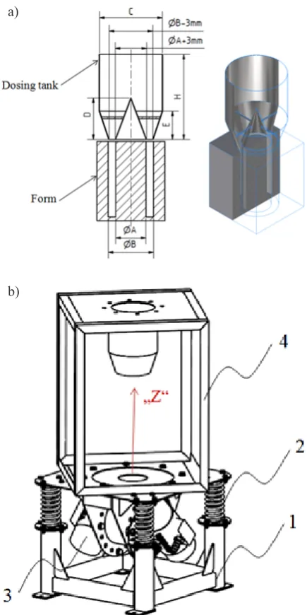
Based on the measured mechanical and physical properties, sand was added into a group of cohesive materials and an external power source was required for uniform emptying of the dosing device. Micro-vibrations with spi-ral path oscillation were selected as an external power source. The shape of the spiral vibration
was achieved by using a pair of NO12 vibration
Fig. 5. Results of angle of repose measurements
Fig. 6. Results of particle size distribution measurements
Fig. 7. a) new design of the dosing device, b) experi -mental stand
a)
motors installed on the vibrating part and
ro-tated by 90° with respect to each other, see Fig. 7b). Vibration motors positioned this way pro
-vide a combination of two harmonic motions:
partial rotation around the “Z” axis and partial feed in the “Z” axis. The combination of these two motions creates spiral micro-oscillation. In this way, the stability and symmetry of the overall assembly during gravitational empty-ing of the dosempty-ing tank are ensured. From the measurement of the external friction angle, a stainless-steel sheet was chosen for the produc-tion of the dosing tank. Based on a comprehen-sive assessment of the measured mechanical and physical properties of the used sand, a new shape and size of the tank was designed, and the minimum dimensions of the discharge out-let were determined, depending on the particle
size distribution of the sand. Figure 7 shows: a) new design of a dosing device, b) experimen -tal measuring stand. The experimen-tal
measur-ing stand consists of the followmeasur-ing basic parts: 1-Fixed frame; 2-Flexible Elements 4x; 3-Vi
-brating part including the dosing tank; 4-Vibra
-tor mo-tors NO12.
EXPERIMENT AND RESULTS
In order to experimentally verify the func-tionality of the optimized dosing tank, a measur-ing apparatus was assembled consistmeasur-ing of the
following: a PC, experimental stand, tensometric
scale and frequency converter. The assembly of
the measuring apparatus is shown in Figure 8. During the experimental measurements, the ef
-fect of vibrations on the efficiency of emptying the dosing tank was assessed. Table 2 shows set -tings of the driving force FB depending on the os-cillation frequency f produced by pair of the N012 0.15kW vibration motors. The total stiffness em -anating from the four elastic elements was kp =
123N.mm-1. A 4 kg sand sample was loaded into
the dosing tank.
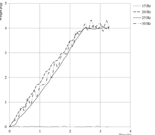
Figure 9 shows the emptying process of the
dosing tank in various operating modes. In the
first experiment, the sand behavior unaffected
by vibrations was monitored. It turned out that the material is so cohesive that the tank could not be emptied by employing only a gravita-tional method. In the second experiment,
vi-brations of 15Hz frequency corresponding to a driving force of 325N were used. Even in
this case, the sand could not be emptied from the tank and the entire volume remained in the
tank. After increasing the frequency to 20Hz, the sand started to freely flow immediately
after opening the discharge outlet. The emp-tying process was smooth with only slight de-viations. Subsequently, the vibration frequency
was set to 25Hz, which corresponds to the driv
-ing force of 904N. In this case, the empty-ing
was very smooth and stable without signs of
impact effects. At 30Hz, there were signs of greater dynamic effects during the emptying
process, which are undesirable for the follow-ing processes. The emptyfollow-ing time for the tested
frequencies was around 2.5s.
Based on the results from the
experimen-tal tests, the final design of the dosing tank was
created, and suitable pneumatic vibration drives
were selected which were positioned 90° relative
to each other. The driving force of a pair of pneu-matic vibration drives was set to allow the
opti-mal emptying of the dosing tank. Fig. 10 shows the final version of the dosing tank design used in
real operation.
CONCLUSIONS
The aim of this research was to optimize the method of emptying a dosing device de-signed for weighing and short-term storage of sand. Firstly, an analysis of the current pro-cess technology was performed. In the follow-ing step, the mechanical and physical
proper-ties of the used sand were measured, namely:
angle of friction, wall friction, angle of re-pose and particle size distribution. Based on the measured values, the sand was assessed as very cohesive with a particle size ranging
from 1μm to 600μm. It was found, that the
most suitable contact material for the pro-duction of the inner space of the dosing tank was stainless steel, which showed the lowest resistance to sand movement. On the basis of the collected data, a new shape and size of the dosing tank was designed, and the minimum
size of the outlet was determined, depending on the particle size distribution of the sand.
Due to the high cohesion of the sand, it was
necessary to introduce external energy to the system. The most suitable vibrations for the process were selected. The shape of the vibra-tion, in the form of harmonic spiral movibra-tion, proved to be the most suitable for the uniform and symmetrical discharge of sand from the tank. The experimental tests showed that the optimal driving force of a pair of vibration
drives was 900N, depending on the weight
of the vibrating parts and the stiffness of the flexible elements. The emptying time of the
required volume of sand ranged around 2.5
seconds. Optimization of the emptying meth-od met all requirements and was applied to real-life operation.
Acknowledgements
This paper was conducted within the
frame-work of the project LO1404: Sustainable de
-velopment of ENET Centre,project SP2018/47:
Calibration and experimental devices for the research and validation of simulation models
AND project SP2018/132: Research and devel -opment of innovative transport equipment for
verification DEM method in process of bulk
solid transportation.
Fig. 10. Dosing tank design
Eksploatacja i niezawodnosc-maintenance and re
-liability, 18(4), 2016, 539-543.
3. Jachowicz T., Sikora R.Methods of forecasting of the changes of polymeric products properties,
Po-limery, 51(3), 2006, 177-185.
4. McGlinchey D. Bulk Solids Handling: Equipment Selection and Operation. Book: Blackwell Pub
-lishing Ltd., 2008, pp: 304.
5. Schulze D. Powders and bulk solids: behavior, characterization, storage and flow. Book: New York: Springer, 2008, pp: 511.
6. Ekmann J. M. and Le P. H. Coal Storage and
Trans-portation. Reference Module in Earth Systems and Environmental Sciences, from Encyclopedia of Energy, 2004, 551-58.
7. Schulze D. Flow Properties of Powders and Bulk Solids [online]. [cit. 2014-04-10]. Accessible from: http://www.dietmar-schulze.de/grdle1.pdf.
Process, 10(3), 1998, 269-274.
11. Bertuola D., Volpato S., Canu P., Santomaso A.
C. Prediction of Segregation in Funnel and
Mass Flow Discharge, Chemical Engineering Sci
-ence, 150, 2016, 16-25.
12. Tian T., Su J., Zhan J., Geng S., Xu G. and Liu X.
Discrete and continuum modeling of granular flow in silo discharge, Particuology, 36, 2018, 127-138. 13. Cleary P.W. Large scale industrial DEM mod
-elling. Engineering Computations, 21(2/3/4), 2004, 169-204.
14. Höhner D., Wirtz S., Scherer V. A study on the in
-fluence of particle shape on the mechanical interac
-tions of granular media in a hopper using the Dis
-crete Element Method, Powder Technology, 278, 2015, 286-305.
![Fig. 1. The principle of dosing cohesive sand into tubular molds [15]](https://thumb-us.123doks.com/thumbv2/123dok_us/8806126.1774650/2.595.310.524.582.744/fig-principle-dosing-cohesive-sand-tubular-molds.webp)