INTRODUCTION
Rapidly growing industry has a high demand for new solutions regarding the quality of coat-ings obtained by using existing and new thermal spraying technologies. One of the major areas of coatings application are devices subjected to abrasive and erosive wear. According to Eyre, the scale of the phenomenon in the industry is around 58% (abrasive wear is about 50% and erosion wear is about 8%). Other mechanisms of wear are: adhesion – 15%, fretting – 8%, chemi-cal wear – 5%, other – 14%. The type of impact of the abrasive grains on the individual material depends on the parameters of the loads carried by the abrasive grains and the nature of movement in relation to the surface of the material [1].
There is no universally accepted classification of abrasive wear in technical literature. P. Solski, having regard to the different degrees of grain freedom, has divided abrasion into: abrasion by fixed grains (grinding), abrasion by abrasive layer
(occurs in the presence of particles in the form of impurities between co-operating machine com-ponents), abrasion in abrasive mass (the wear-ing process of agricultural machinery), abrasive flux (erosion – occurs when the impact process of abrasive grains on the material is dynamic) [2].
Some micro-mechanisms occurring in abra-sive wear processes are similar to eroabra-sive wear processes. These mechanisms have been de-scribed by Winter and Hutchings using the sin-gular sharp-edged particles for research. Micro-cutting and micro-grooving were observed, as well as the presence of adiabatic shear bands. In the study of micro-mechanisms of abrasive wear, the influence of adhesion forces between the inci -dence particle and the material on the formation of wear products has been determined as signifi -cantly affecting [3]. The erosion wear of ductile materials depends on certain factors, including: incidence angle and particle velocity; shape, size and mechanical properties of the particle; tem-perature, size and shape of the eroded surface; the
THE INFLUENCE OF MICROSTRUCTURE OF ARC SPRAYED COATINGS
ON WEAR RESISTANCE
Daniel Majewski1, Tadeusz Hejwowski1, Daniel Łukasik1
1 Lublin University of Technology, Faculty of Mechanical Engineering, Department of Materials Engineering, 36 Nadbystrzycka St., 20-618 Lublin, Poland, e-mail: daniel.majewski@pollub.edu.pl, t.hejwowski@pollub.pl, d.lukasik@pollub.pl
Research Journal
Volume 12, Issue 1, March 2018, pages 285–292
DOI: 10.12913/22998624/86210 Research Article
ABSTRACT
The paper presents the test results of microstructure and resistance to abrasion and erosive wear of single and double-layer coatings with arc-coated powder wires on the
iron matrix. It was shown that adhesion of coatings is in the range of 14.39 – 24.72
MPa. The closed porosity of the coatings determined from SEM images is in the range
of 0.69 – 2.45% and was significantly lower than the porosity determined from the images obtained from the optical microscope, which was 5.49 – 8.11%. The 95 MXC
coating’s hardness of the matrix was about 100HV0.05 higher compared to the AMI 100 coating matrix. The intensity of the erosion of AMI 100 coatings was lower than the
intensity of the erosion of 95 MXC coatings.
Keywords: microstructure, microhardness, wear resistance, sprayed coatings, quan-titative metallography.
Received: 2017.12.12
Accepted: 2018.02.01
type of carrier gas or environment, and the pres-ence of admixtures in the abrasive [4].
One of the most important properties of the coatings is their porosity. For cermet coatings, achieving a porosity of less than 5% is beneficial for improving erosion resistance [5]. In erosion tests of cermet coatings for the 90° incidence an -gle, cracking and spattering of large grains were observed in the coating. For a 30° incidence an -gle, a significant reduction in roughness was ob -served due to the presence of micro-cutting pro-cesses [6]. Arc-sprayed coatings are used in the case of erosion – corrosion in the fluidised bed boiler. They are obtained from materials such as Ducor (WC – 26%, Cr – 14%, B – 1.87%, Si – 1.25%, Mn– 0.55%), Armacor M (B – 3.75%, Cr – 2.9%, Mn– 1.65%, Si – 1.6%, Fe – other), as well as Alpha 1800 (B – 6.1 ÷ 9.5%, Si – 0.02 ÷ 1%, Al – 0.02 ÷ 1%, C – 0.06 ÷ 0.6%, Fe – oth -er). For the last of the given materials the coating thicknesses losses were 3 to 7 times lower than non-alloy steel at temperatures up to 600 °C [7].
The micro-structure of arc-coated coatings has been the subject of a few and fragmented pub-lications. The aim of this study was to present the results of the research (porosity, micro-hardness, microstructure, abrasion and erosion wear resis-tance, adhesion and EDS) on metallic arc-sprayed coatings and micro-structure influence on abra -sion and ero-sion.
METHODOLOGY OF RESEARCH
The subjects were arc-sprayed coatings on five test panels using the TAFA 8835 arc spray -ing system (arc current – 250A, voltage – 32V, operating pressure – 0.5MPa). For microscopic studies 13CrMo4–5 steel washers were made. Prior to the spraying process, the base materi-als were sandblasted with loose abrasive. The primer layers were sprayed with 75B chemical powder Al – 4.5%; Ni – 93.95% (layer thickness – 0.2 mm). The wear resistant layers (layer thick-ness – 0.3 mm) were made of powdered wires – 95 MXC with chemical composition C – 0.15%; Si 1.2 – 2%; Cr – 26 ÷ 29%; Mn– 1.1 ÷ 2%; B – 3.3 ÷ 4%; Fe – other, and AMI SPRAY ARC 100 with chemical composition C – 2.8%; Cr – 19%; Fe – other. Surface roughness studies have shown that Ra is greater than 40 μm. Chemical com -position of 13CrMo4–5 steel: C 0.11 – 0.18%; Mn 0.4 – 0.7%, Si 0.15 – 0.35%; Cr 0.7 – 1%;
Mo 0.4 – 0.55%, Cu <0.25%; Ni <0.35% and the chemical composition of 10CrMo9–10 steel is C 0.08 – 0.15%; Mn 0.4 – 0.6%, Si 0.15 – 0.50%; Cr 2 – 2.5%; Mo 0.9 – 1.1%, Cu <0.25%; Ni <0.3%.
The materials for the microscopic examina-tion were cut on a Struers Secotom – 10 metal-lographic cutter with coolant. The selected feed rate for the cut material was 0.1 mm/min. The cut specimens were housed in a chemo-hardened ep-oxy resin. The samples were ground and polished on a Mintech Z63 grinding machine. The final polishing step was performed on a 3 μm diamond suspension liquid. Microstructure photos were taken on the Nikon Eclipse MA100 microscope equipped with a digital camera. Based on images from microscope, closed porosity analysis was performed. Porosity was measured based on 60 images for each material. The SEM analysis was performed on the PHENOM Pro X scanning mi -croscope to analyse the surface and cross-section of the coatings. Analyses of the porosity of micro-structures and images from scanning electron mi-croscope and optical mimi-croscope were performed in Image Pro Plus. Open porosity was tested on the basis of the results of 6 SEM images for each sample. Closed porosity was investigated using 15 SEM images for each sample. Micro-hard-ness was tested by the FM-800 testing machine. Measurements were conducted using the Vickers method (fifteen measurements for each of the six samples of the material). The load was 0,49N, duration 10s.
Adhesion tests were performed according to DIN EN 582. The coatings were sprayed on flat surfaces of Ø40 x 7.5mm. The coated surfaces were ground on a magnetic grinder to obtain a uniform geometry of the test surface. The adhe-sion tests were performed on a Cometech QC-503 B1 (F ≤ 100 kN) testing machine. The durable connection between the spindle and the coating surface was obtained with thermosetting epoxy glue 3M Scotch Weld Epoxy Adhesive 2214.
Abrasion tests were performed on the T-07 laboratory tester. The pressure of the rubber roller was 22N. The test time was 300 s. The test was also performed for the S235JR steel control mate -rial and was carried out under the same conditions as for the other samples. The abrasive used in the test was Al2O3 with 120 grains. The relative inten-sity of abrasive wear was determined as the ratio of the loss of mass of the test sample to the loss of mass of the control sample.
TEST RESULTS AND DISCUSSION
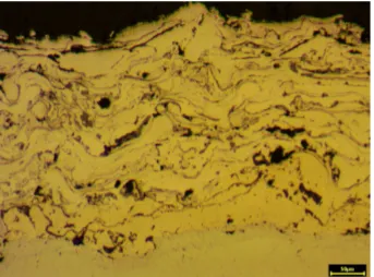
Photos of microstructures obtained from the optical microscope revealed numerous coating defects characteristic for thermal spraying pro-cesses. Fig. 1 shows the microstructure of the AMI 100 coating on which the coating lamellae and partially untreated particles are visible. Further-more, oxides and pores occur in the microstruc-ture. The pore size of the coatings has a bimodal distribution [8]. After the spraying process, the coating displayed characteristic large horizontal cracks, which were formed both at the substrate and at the top layer. Different orientation and size of cracks indicate that they may have formed as a result of metal solidification [9]. In the spraying process, the oxides were formed primarily during the interaction of liquid metal droplets with oxy-gen in the air stream, and also immediately after
settling before the liquid particle cooled. Oxides often have a characteristic spherical shape due to their immiscibility with molten metal [10].
Due to the presence of micro-cracks, cracks and pores in the microstructure, porosity is an important parameter determining the mechani-cal properties of the coating [11]. There are not many works on the nature of the pore distribution in the coating’s microstructure. Moreover, there are no exact measurements of porosity, which sig-nificantly limits the results of the analysed micro -structures [12,13]. Fig. 2 shows how to quantify the pores in the coating’s structure. In the anal-ysed SEM image of 95 MXC material, only pores were marked (not oxides and impurities). The av-erage open porosity of the 95 MXC non-polished coating was 19.90% (Table 1). The structure of 95 MXC shows much higher porosity before ero -sion (Fig. 2) than after ero-sion (Fig. 5, tab.1). The average values of the open pores post ero-sion test results for the AMI 100 coating are simi-lar to the results obtained from the closed pores by optical microscopy. The open porosity of the coatings measured after the erosion tests of the AMI 100 layer was similar. AMI 100 monolayer coatings show the dependency between the ob-tained results of abrasion tests and erosion studies and open porosity. The intensity of erosion reduc-es with decreasing porosity and the intensity of abrasive wear for the polished coating increases relatively to the non-polished coating. For a 95
MXC non-polished coating, lower porosity was obtained after erosion with 90° incidence angle than at a 30° angle. Tables 1 and 3 prove that for the non-polished coating 95 MXC, with the de -crease of open porosity, the relative intensity of erosive wear decreases.
The results for the closed porosity test based on SEM images are shown in Table 2, and the po-rosity results obtained from optical microscopy images are shown in Figure 3. During the analy -sis of the closed porosity based on SEM images and microstructures from optical microscopy, re-sulted in inconsistent data. The average porosity of 95 MXC coatings (Fig. 3) was 5.49%, and for AMI 100, 8.11%. The porosity calculated on the basis of SEM images was about 2.4% for AMI 100 and about 1% for 95 MXC. Differences in results arose as a result of choosing the method
of image analysis. In the microstructure studies with optical microscope, oxides are treated as porosity, as well as numerous propagation cracks in various directions. During porosity studies, the analysis of SEM images does not take into account larger cracks and large precipitations of oxides (oxides and inclusions are very well vis-ible at high magnifications of SEM images, as shown in Fig. 2). Analysis of the closed porosity of SEM images revealed small pores at the grain boundaries caused by thermal contraction of the cooling metal particles.
The obtained results of microhardness mea-surements are characterised by quite large scat-tering of experimental data, which is typical for thermally sprayed coatings [14]. The results of microhardness measurements are shown in Fig. 4. The 95 MXC coatings with lower porosity than AMI 100 and Boron in chemical composition are characterised by much higher microhard-ness. Measured extreme values for the 95 MXC + primer layer are as high as 1800 HV0.05, while the average values oscillate at the limit of 1150 HV0.05. For the examined coatings, the grouping of extreme results was observed, especially vis-ible for 95 MXC (1200 ÷ 1300 HV0.05). Coatings with the primer layer showed higher average mi-crohardness values. The 75B/95 MXC coating, a significant increase in extreme values (above
Table 1. The average open porosity calculated based on SEM images
AMI 100 AMI 100 eroded at a 30° angle AMI 100 eroded at a 90° angle 95 MXC 95 MXC eroded at a 30° angle 95 MXC eroded at a 90° angle
14.04 % 8.25% 8.14% 19.90% 10.97% 7.68%
Fig. 2. SEM images: a) 95 MXC after spraying, b) analysis of open porosity in Image Pro Plus.
Table 2. Closed porosity calculated based on
SEM images
Coating images examinedThe number of Average porosity (%)
AMI 100 15 2.42
AMI 100 + 75B 15 2.45
95 MXC 15 1.09
1500 HV0.05) was observed relative to the 95 MXC coating. The AMI 100 and 75B/AMI 100 coatings, the extreme lower values were similar, while the upper ones were higher for 75B/AMI 100. The average microhardness of the one and two-layered AMI 100 coatings was similar.
SEM images of the eroded coatings surface are shown in Fig. 5 ÷ 6. During the coatings ero -sion, the surface layer of the material has been removed. Coatings eroded at an angle of 90° are characterised by an even surface with numerous cracks and chippings of particles in the surface layer. The AMI 100 coating (Fig. 6-b) has a lower hardness than the 95 MXC coating (Fig. 5-b) and is characterised by a greater number of
micro-cracks and cavities similar to pores compared to the 95 MXC coating. For coatings eroded at an angle of 30° (Fig. 5-a, 6-a), defects in the coat -ing due to chipp-ing are less numerous than those eroded at an angle of 90° (Fig. 5-b and 6-b). The main features of the eroded layers at an angle of 30° (Figures 5-a and 6-a) are large pores, and vis -ible micro-gaps in the structure (Fig. 5-a). The hard particles are removed when the matrix mate-rial around them has been eroded [1]. Additional-ly, the arrow in Fig. 6-a indicates the area with an increased carbon concentration (13%). This may indicate the presence of carbide or carbide phase in this place. A large loss of the matrix is visible next to the marked area.
Fig. 4. Microhardness tests chart.
Fig. 3. Closed porosity calculations results for optical
microscope images.
The intensity of the tested erosion of the 95MXC monolayer coating and the two-layered 75B/95MXC coating is higher for an angle of in -cidence of 30° than at the angle of 90° (Table 3). The intensity of erosion of non-grounded coat-ings is about three times higher than the intensity of erosion of grounded coatings, which is associ-ated with removing the unevenness of the coating during erosion. The 95 MXC grounded and dou -ble-layered coating containing the 95MXC layer has a higher erosion intensity for a normal angle of incidence. The intensity of erosion of AMI 100 and double-layered 75B/AMI 100 coatings is higher at an angle of 30°. The difference in the intensity characteristics of the erosion of 95 MXC and AMI 100 coatings is related to the hardness of the material [1]. For the AMI 100 coating, ero-sion tests at both 30° and 90° are varied. This is due to much lower hardness of the AMI 100 coat-ing relative to the 95 MXC coatcoat-ing. One and two-layer AMI 100 coatings show a lower intensity of erosive wear at a normal angle (Fig. 6-b). The AMI 100 coating was characterised by lower in-tensity of erosion wear for 95 MXC non-ground coatings (especially at an angle of 30°). For AMI 100 and 75B/AMI 100 ground coatings, the ero -sive wear intensity was lower at an angle of 90° with respect to 95 MXC and 75B 95 MXC, and at an angle of 30°, these values were similar (except for the 95 MXC coating). The difference in the erosion resistance of one and two-layer coatings
is related to different coating forming conditions and high internal stresses in the sprayed coatings. The porosity and hardness of the coating have a significant influence on erosion [15].
Wear-resistant coatings have been widely used, mostly for tribological applications for the protection of aluminium alloys [16]. The litera-ture on the resistance of coatings to wear with different chemical compositions indicates that the nature of wear is closely related to the conditions of the test [17, 18]. The intensity and nature of abrasive wear is influenced by many factors such as: porosity, chemical composition of the coat-ing, number of inclusions, cracks or parameters of the spraying process. Table 4 shows the results of abrasive wear tests. Coatings with primer lay -ers showed higher average abrasion intensity than coatings without a primer. The 95 MXC coatings without a primer layer with boron in their chemi-cal composition are characterised by a lower rela-tive intensity of abrasive wear in relation to AMI 100 coatings. An important aspect is the results obtained for 95 MXC and AMI 100 ground coat -ings where the relative intensity of abrasive wear is significantly higher than that of non-ground coatings. The results for the AMI 100 and 95 MXC monolayer coatings are related to the fact that when trying to abrade the rough coating, the abrasive grains occupy space in the unevenness of the coating. They provide support for counter-sample, which has reduced abrasive wear. For
75B/95MXC and 75B/ AMI 100 coatings, the relative intensity of abrasive wear is higher for non-ground coatings. No influence of porosity on abrasive wear intensity tests was observed.
To determine the strength of the bond be-tween the coating and the base, adhesion tests were carried out in accordance with DIN EN 582. The results are presented in Table 5 ÷ 6. Adhesion of the coating is one of the decisive factors deter-mining its applicability. Factors such as chemical properties of the material, base roughness, coeffi -cients of thermal expansion of the base, coatings, as well as factors related to the deposition process (such as microstructure, internal stresses, thick-ness and presence of impurities, and structural defects in the coating) affect the adhesion of the coating to the base [19,20]. The highest adhesion was noted for materials sprayed on 10CrMo9–10 steel. The highest adhesion tested was noted for the 95 MXC sample and it was 35.67 MPa. Higher adhesion was obtained by coatings char-acterised by high elongation of the tested sample. The minimum adhesion of the AMI 100 coating sprayed on 13CrMo4–5 and 10CrMo9–10 steels is similar, but the average maximum values are much higher. In the adhesion tests of the 95MXC coating, a similar dependence is observed. The fractures were mixed (cohesive-adhesive). Dif-ferences in elongation are associated with differ -ent cohesion and adhesion rates.
CONCLUSIONS
Microstructure investigations revealed nu-merous cracks between the coating and the base material, as well as in the top layer of the coating. The pores observed between the coating and the substrate could have a significant effect on the ad -hesion parameter. The intensity of erosion wear at an angle of 30° to the angle of 90° is higher in non-ground coatings. Open porosity is dependent to the angle of erosion. For AMI 100 coatings, eroded with incidence angle 30° and 90°, the open porosity is similar to the results of closed poros-ity calculated on the basis of optical microscope images. Closed porosity measured from SEM images is several times lower than average po-rosity results from light microscopy images. The relative intensities of abrasive wear of ground and non-ground coatings are similar to each other. The coatings sprayed on 10CrMo9–10 steel show higher adhesion in tensile tests. The coatings sprayed onto the primer layer 75B show higher microhardness. The AMI 100 coatings show the presence of the carbide phases. The 95 MXC coatings containing 3.3 – 4% boron, allowed for forming of carbide and boride phases, with a hardness of 1200 ÷ 1300 HV0.05 (for 95 MXC) and 1500 ÷ 1700 HV0.05 (for 75B/95 MXC coating). The described coatings are suitable for use in heat exchangers such as the OP – 215 energy boiler.
Table 3. Results from erosive wear tests.
Material intensity [mg/g] (for Average erosion 90° angle)
Average erosion intensity [mg/g] (for 30°
angle)
Average erosion intensity [mg/g] (for 90° angle),
ground surface
Average erosion intensity [mg/g] (for 30° angle),
ground surface
95 MXC 2.18 2.37 0.79 0.57
95 MXC + 75B 2.13 2.35 1.2 0.78
AMI 100 1.75 1.77 0.62 0.74
AMI 100 + 75B 1.45 1.62 0.72 0.82
Table 4. Results from abrasive wear tests.
95 MXC 75B/95 MXC AMI 100 75B/AMI 100
Relative average intensity of abrasive wear of non-ground
coatings 0.96 1.31 1.11 1.42
Relative average intensity of abrasive wear (for ground
coating) 1.13 1.27 1.55 1.35
Table 5. Test results from the AMI SD 6.5 + 95 MXC tensile test.
Base material Average elongation (%) Elongation – range (%) Average adhesion (MPa) Adhesion range (MPa)
13CrMo4–5 4.11 2.81 – 5.43 16.31 12.43 – 22.01
REFERENCES
1. Hejwowski T.: Nowoczesne powłoki nakładane cieplnie odporne na zużycie ścierne i erozyjne. Po
-litechnika Lubelska, Lublin 2013
2. Solski P.: Zużycie cierne metali, WNT
Warszawa 1968.
3. Winter, R.E., Hutchings, I.M.: Solid particle ero-sion studies using single angular particles. Wear
1974, vol. 29, str. 181 – 194.
4. Parslow G.I., Stephenson D.J., Strutt J.E., Tetlow
S.: Investigation of solid particle erosion in
com-ponents of complex geometry. Wear 1999, vol. 233–235, str. 737–745.
5. Bergmann C.P., Vincenzi J.: Protection against ero -sive wear using thermal sprayed cermet. A review.
Springer-Verlag, Berlin, 2011.
6. Hejwowski T.: Studium procesów zużywania erozyj
-nego, ściernego i zmęczenia cieplnego elementów maszyn oraz kształtowanie struktur o korzystnych właściwościach eksploatacyjnych. Wydawnictwo Uczelniane Politechniki Lubelskiej 2003.
7. Venugopal K., Agrawal M.: Evaluation of arc sprayed coatings for erosion protection of tubes
in atmospheric fluidized bed combustion (AFBC) boilers. Wear 2008, vol. 264, str. 139–145.
8. Lima R.S., Marple B.R.: Thermal spray coat -ings engineered from nanostructured ceramic ag-glomerated powders for structural, thermal barrier
and biomedical applications: a review. Journal of Thermal Spray Technology 2007, vol. 16, nr 1, str. 40–63.
9. Xuemei S., Fangli M.,Mingguang K.,Ziwei L.,Liping H.,Xuebin Z.,Yi Z.: Relationship between cracks and microstructures in APS YSZ coatings at elevated temperatures. Materials Characterization, Volume 131, September 2017, Pages 277–284.
10. Deshpande S., Sampath S., Zhang H.: Mechanisms of oxidation and its role in microstructural evolu-tion of metallic thermal spray coatings – case study
for Ni-Al. Surf. Coat. Technol., 200 (2006), pp. 5395–5406
11. Chao Z.,Wei T. i inni: Microstructure and porosity
evaluation in laser-cladding deposited Ni- based
coatings. Surface and Coatings Technology. Vol
-ume 294, 25 May 2016, Pages 122–130
12. F. Cernuschi, I.O. Golosnoy, P. Bison, A. Moscatel
-li, R. Vassen, H.P. Bossmann, S. Capelli: Micro -structural characterization of porous thermal bar-rier coatings by IR gas porosimetry and sintering
forecasts. Acta Mater., 61 (1) (2013), pp. 248–262 13. Wang Y., Gauvin R. i inni: Panoramic statistics on
porosity and microstructural features of plasma
sprayed Y2O3-ZrO2 thermal barrier coatings. Sur
-face and Coatings Technology. Volume 316, 25 April 2017, Pages 239–245
14. Giovanni B., Marcello B., Luca L., Tiziano M.,
Ville M., Rinaldo R., Paolo S., Petri V.:
Tribol-ogy of FeVCrC coatings deposited by HVOF and
HVAF thermal spray processes. WearVolumes
394–395, 15 January 2018, Pages 113–133.
15. Lei Q.,Yuping W.,Sheng H.,Jianfeng Z.,Wei S.,Yugui Z.: Relationships between spray param -eters, microstructures and ultrasonic cavitation erosion behavior of HVOF sprayed Fe- based amorphous/nanocrystalline coatings. Ultrasonics
Sonochemistry. Volume 39, November 2017, Pag
-es 39–46
16. G. Bolelli, B. Bonferroni, G. Coletta, L. Lusvarghi,
F. PitaccoWear and corrosion behaviour of HVOF
WC-CoCr/CVD DLC hybrid coating systems deposited onto aluminium substrate. Surf. Coat.
Technol., 205 (2011), pp. 4211–4220
17. F. Madah, C. Dehghanian, A.A. Amadeh: Inves -tigations on the wear mechanisms of electroless
Ni-B coating during dry sliding and endurance life of the worn surfaces. Surf. Coat. Technol., 282
(2015), pp. 6–15
18. M. Magnani, P.H. Suegama, N. Espallargas, S.
Dosta, C.S. Fugivara, J.M. Guilemany, A.V. B enedetti: Influence of HVOF parameters on the corrosion and wear resistance of WC-Co coatings sprayed on AA7050 T7.Surf. Coat. Technol., 202 (2008), pp. 4746–4757
19. Shigeyasu A.,Tohru H.: Planar fractal character-istics of blasted surfaces and its relation with
ad-hesion strength of coatings. Surface and Coatings Technology. Volume 130, Issues 2–3, 21 August 2000, Pages 158–163
20. Drábik M.,Truchlý M.,Ballo V.,Roch T., Kvetková L.,Kúš P.: Influence of substrate material and its
plasma pretreatment on adhesion and properties of
WC/a-C:H nanocomposite coatings deposited at low temperature. Surface and Coatings Technol
-ogy. Volume 333, 15 January 2018, Pages 138–147
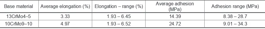
Table 6. Test results from the AMI SD 6.5 + AMI SPRAY ARC 100 tensile test.
Base material Average elongation (%) Elongation – range (%) Average adhesion(MPa) Adhesion range (MPa)
13CrMo4–5 3.33 1.93 – 6.45 14.39 8.38 – 28.7