R E S E A R C H
Open Access
Wind noise reduction for a closely spaced
microphone array in a car environment
Simon Grimm
*and Jürgen Freudenberger
Abstract
This work studies a wind noise reduction approach for communication applications in a car environment. An endfire array consisting of two microphones is considered as a substitute for an ordinary cardioid microphone capsule of the same size. Using the decomposition of the multichannel Wiener filter (MWF), a suitable beamformer and a
single-channel post filter are derived. Due to the known array geometry and the location of the speech source, assumptions about the signal properties can be made to simplify the MWF beamformer and to estimate the speech and noise power spectral densities required for the post filter. Even for closely spaced microphones, the different signal properties at the microphones can be exploited to achieve a significant reduction of wind noise. The proposed beamformer approach results in an improved speech signal regarding the signal-to-noise-ratio and keeps the linear speech distortion low. The derived post filter shows equal performance compared to known approaches but reduces the effort for noise estimation.
Keywords: MVDR beamforming, Multichannel Wiener filter, Wind noise reduction, Speech signal processing, MEMS microphones
1 Introduction
Hands-free communication applications in a car environ-ment always face the problem of unwanted noise com-ponents in the microphone signals. Commonly, single-channel algorithms like the Wiener filter and spectral subtraction are used for noise suppression [1, 2]. Multi-channel approaches are able to improve the speech quality further [3–6]. Considering more than one microphone, closely spaced microphones are often used in commu-nication systems for signal augmentation by forming a differential microphone array [7–11]. This allows to cre-ate a directivity-dependent beam pattern to augment a desired signal direction, while suppressing noise coming from other incident angles.
The use of micro-electro-mechanical system (MEMS) microphones as a replacement for ordinary microphone capsules has gained interest in [12–14], especially for the application of directive beamforming [15, 16] due to its reduced size and cost compared with an ordinary micro-phone capsule. However, differential micromicro-phone arrays
*Correspondence:[email protected]
Institute for System Dynamics, HTWG Konstanz, University of Applied Sciences, Alfred-Wachtel-Strasse 8, 78462 Konstanz, Germany
are not ideal in the presence of wind noise. The direc-tional beam pattern may lead to a significant amplification of the wind noise due to the correlation properties of the noise terms [17]. The required first-order low-pass filter for the equalization regarding the speech signal makes this behavior even worse. One proposed solution for a differ-ential microphone array is to switch to a single micro-phone with an omnidirectional response if wind noise is detected [17].
Besides car noise, wind noise components often occur in hands-free communication applications in a car environ-ment, caused by open windows, fans, or open convertible hoods that create airflow turbulence over the microphone membranes and result in low frequency signal compo-nents of high amplitude [18].
Noise reduction algorithms in car environments are typically based on the assumption that the noise is sta-tionary or varies only slowly in time. In [19], Wilson et al. demonstrated that wind noise consists of local short-time disturbances which are highly non-stationary. This makes the reduction of wind noise a challenging task. The sup-pression of wind noise is mostly covered in the context of digital hearing aids or mobile devices in the literature [17, 20, 21]. For single-channel wind noise reduction,
often the different power spectral density (PSD) proper-ties of speech and wind noise are exploited [17,20,22]. Several other methods exist that aim to reduce wind noise for a single microphone [23–27].
The utilization of more than one microphone allows to take the diversity of the sound field into account to indicate wind noise and reduce it successfully. In [20], a spectral weighting filter based on the coherence between two microphones is proposed. The coherence is also used in [28], where in addition to the magnitude squared coherence (MSC) the information that relies on the phase component is applied to synthesize a spectral filter function.
In [29], the decomposition of the multichannel Wiener filter into a minimum variance distortionless response (MVDR) beamformer and a single-channel Wiener post filter for an arbitrary microphone arrangement is pre-sented. The approach is based on the assumption that the wind noise is uncorrelated at the microphones, while having equal noise power spectral densities, but arbitrary acoustic transfer functions (ATFs). From these assump-tions follows for closely spaced microphones that a sim-ple delay-and-sum (DS) beamformer achieves maximum signal-to-noise-ratio (SNR) beamforming, because equal ATFs from the speech source to the microphones can be assumed for low frequencies.
In this work, we propose a wind noise reduction approach for a closely spaced microphone array consist-ing of two MEMS microphones, which is considered as a substitute for an ordinary cardioid microphone cap-sule. The decomposition of the MWF in a beamformer and a single-channel post filter is used similar to [29] as well as the assumption that the wind noise is uncor-related at the microphones. But in contrast to [29], we assume that the noise powers at the microphones may differ. Since the geometry of the microphone array and the location of the desired speech source are known, additional assumptions about the speech and noise sig-nal properties can be made to design a low-complexity wind noise reduction algorithm. Even for distances of only a few centimeters, the variation in the microphone signals can be used to reduce wind noise significantly. The coherence properties of speech and wind noise sig-nals are exploited to form a beamformer, as well as to obtain estimates of the speech and noise PSDs for the post filter. Simulations with recorded wind noise show that the proposed approach improves the signal-to-noise-ratio, while keeping the linear distortion of the speech signal low.
The remainder of this paper is structured as follows. The signal model and the notation are briefly introduced in Section2. In Section3, the proposed wind noise reduction approach is presented. Simulation results are discussed in Section4, followed by a conclusion in Section5.
2 Signal model and notation
In the following, the signal model and the notation is briefly explained. We consider a linear MEMS micro-phone array, which is mounted in a car in front of the speaker’s seat in an endfire configuration. The acoustics in the car environment are considered as linear and time invariant. Using the the sub-sampled time indexκand the frequency bin index ν, the spectrum Yi(κ,ν) of the ith microphone can be written in the short-time frequency domain as
Yi(κ,ν)=Hi(ν)X(κ,ν)+Ni(κ,ν), (1) where X(κ,ν) corresponds to the short-time spectrum of the speech signal. Hi(ν)denotes the acoustic transfer function, Si(κ,ν) = Hi(ν)X(κ,ν)is the spectrum of the speech component, and Ni(κ,ν) is the spectrum of the noise at theith microphone. For two microphones, the signals can be written as vectors
S(κ,ν)=[S1(κ,ν),S2(κ,ν)]T (2)
N(κ,ν)=[N1(κ,ν),N2(κ,ν)]T (3)
H(ν)=[H1(ν),H2(ν)]T (4)
Y(κ,ν)=S(κ,ν)+N(κ,ν). (5)
Vectors and matrices are written in bold, and scalars are normal letters. T denotes the transpose of a vec-tor, ∗ denotes the complex conjugate, and† denotes the
conjugate transpose.
We assume that the speech and noise signals are zero-mean random processes with the short-time power spec-tral densities 2Ni(κ,ν) and 2S
i(κ,ν) at the ith micro-phone. It is assumed that the speech and noise terms are uncorrelated. The noise correlation matrix can be expressed as
RN(κ,ν)=E
N(κ,ν)N(κ,ν)†
(6)
and similar the speech correlation matrix as
RS(κ,ν)=ES(κ,ν)S(κ,ν)†=2X(κ,ν)HH†, (7) where E denotes the mathematical expectation and 2
X(κ,ν)the PSD of the clean speech signal. Due to the short-time PSD fluctuations, the PSDs are time and fre-quency dependent. However, for briefness, the indices (κ,ν)are often omitted in the following.
3 Wind noise reduction algorithm
wind noise components at low frequencies and neglect the slowly varying driving noise. Such stationary noise com-ponents can be estimated and reduced by state-of-the-art noise reduction approaches.
The proposed wind noise reduction approach is derived from the commonly used speech distortion weighted mul-tichannel Wiener filter [3], which is defined as
GMWF=(RS+μRN)−12XHH˜∗ (8)
whereH˜ is the acoustic transfer function of an arbitrary chosen microphone channel.μis a noise overestimation parameter which allows a trade-off between noise reduc-tion and speech distorreduc-tion. The output signalZMWFof the Wiener filter is obtained by
ZMWF=Y·GMWF
†
. (9)
In [30,31], it is shown thatGMWFcan be decomposed into an MVDR beamformer
GMVDR= R
−1 N H
H†R−1
N H
(10)
and a single-channel Wiener post filter
GWF= γ
out
γout+μ (11)
as
GMWF=GMVDR·GWF· ˜H∗. (12)
The termγout is the narrow-band SNR at the beam-former output which is defined as
γout=trR SR−1N
, (13)
where tr(·) denotes the trace operator. We exploit this decomposition for the proposed wind noise reduction. Firstly, we derive a beamformer for the considered micro-phone setup.
3.1 Beamformer
In the following, we consider time-aligned signals where the alignment compensates the different times of arrival for the speech signal. This is achieved by delaying the front microphone with a suitable sample delayτ to be in phase with the rear microphone,
ˆ
Y1(ν)=Y1(ν)·
e−j2πνLτ forν∈0,. . .,L
2−1 ej2πνLτ forν∈ L
2,. . .,L−1 (14)
whereLdenotes the block length of the short-time Fourier transform. After this alignment, we assume that the ATFs in H are identical, because the low frequency speech components have a large wavelength compared with the microphone distance.
H= ˆH1=H2 (15)
H=H·[ 1, 1]T (16)
which leads to the speech correlation matrix depend-ing only on the PSD of the speech signal at one of the microphones
RS=2X|H|2
1 1 1 1
=2
S
1 1 1 1
. (17)
Furthermore, it can be assumed that the wind noise terms for both microphone signals are uncorrelated even for small distances of the microphones [28,32]. This sim-plifies the noise correlation matrix as well as its inverse since the cross-terms can be neglected
R−1N =
⎛ ⎝
1 2
N1 0
0 1
2
N2 ⎞
⎠. (18)
The numerator term of theGMVDRin (10) can be writ-ten as
R−1N H=H·
⎛ ⎝
1 2
N1
1 2
N2 ⎞
⎠ (19)
and the denominator as
H†R−1N H= |H|2·
1 2
N1
+ 1
2
N2
. (20)
SinceHis not known, it is set toH = 1. This results in the minimum variance (MV) beamformer coefficients
GMVi = 1 2
Ni
1 2
N1 +
1 2
N2
, (21)
which can be interpreted as a noise-dependent weight-ing of the input signals. Note that the MV beamformer achieves the same narrow-band output SNR as the MVDR beamformer but no distortion-free response [5]. Finally, the output of the beamformer can be written as
YMV =
ˆ
Y1·G1MV+Y2·GMV2
. (22)
Using (17) and (18), we are able to calculate the narrow-band output SNR of the beamformer as
γout=2
S·
1 2
N1
+ 1
2
N2
= 2S 2
Nbeam
, (23)
where2N
beam denotes the noise PSD at the beamformer
output. This PSD can be calculated as
2
Nbeam =
2
N1·
2
N2
2
N1+
2
N2
. (24)
3.2 Special cases
the simple weighting of a delay-and-sum beamformer (a simple summing of the aligned signals)
GDSi = 1 2
N1
1 2
N1 +
1 2
N1
= 1
2, (25)
which results in the output signal
YDS= 1 2
ˆ
Y1+Y2
. (26)
A delay-and-sum beamformer is also proposed in [17] for closely spaced microphones with wind noise.
We keep the condition of uncorrelated noise terms and assume a special case where the short-time noise PSDs are varying over time and frequency. This is motivated by the highly non-stationary local short-time wind noise dis-turbances [19] and implies that only one microphone is affected by wind noise at any given time and frequency indexκandν
2
N1(κ,ν) <<
2
N2(κ,ν) (27)
or
2
N1(κ,ν) >>
2
N2(κ,ν). (28)
Then, the noise PSD-dependent weighting in (21) reduces to a selection approach of the dedicated frequency bins by comparing the short-time PSDs of the micro-phone signals2Y
i, because the speech signal PSDs
2
Siare assumed to be identical for both microphones. Therefore, the resulting output signalYFBScan be written as
YFBS(κ,ν)=
Y1(κ,ν), 2Y1(κ,ν) <
2
Y2(κ,ν)
Y2(κ,ν), 2Y1(κ,ν) >
2
Y2(κ,ν)
(29)
3.3 PSD estimation
Next, we derive estimates for the speech and noise PSDs which are required for the beamformer and post filter. As mentioned in [29], most single-channel noise estimation procedures (i.e., [33–35]) rely on the assumption that the noise signal PSDs are varying more slowly in time than the speech signal PSD. This is not the case for wind noise. The fast varying short-time PSDs make noise estima-tion a challenging task for a single microphone. However, using more than one microphone, the different correlation properties for speech and wind noise can be used for the estimation.
A reference for the wind noise can be obtained by exploiting the fact that the wind noise components in the two microphones are incoherent while the speech components are coherent. To block the speech signal, a delay-and-subtract approach is used to obtain a noise reference
N= Yˆ1−Y2
2 , (30)
which depends only on incoherent wind noise terms. The PSD of this noise reference is
2
N = E
NN∗ (31)
= E
ˆ
Y1−Y2 2
ˆ
Y1−Y2 2 ∗ (32) = 1 4
EYˆ1Yˆ1∗
−EYˆ1Y2∗
−EY2Yˆ1∗
+EY2Y2∗
(33)
= 1
4
ENˆ1Nˆ1∗
−ENˆ1N2∗
−EN2Nˆ1∗
+EN2N2∗
. (34)
The cross-terms vanish, because the wind noise terms are uncorrelated. Hence, we obtain
2 N = 2 N1 4 + 2 N2
4 . (35)
Note that the delay-and-subtract signal in (30) is used in other applications as the output of a differential micro-phone array [17]. Obviously, this is not suitable for micro-phone positions that are sensitive to wind noise, because the noise terms are heavily amplified.
By summing the aligned signals according to (26), we augment coherent signal components. The combined sig-nalYDShas the PSD
2
YDS = E
YDSYDS∗
(36)
= E
ˆ
Y1+Y2 2
ˆ
Y1+Y2 2 ∗ (37) = 1 4
EYˆ1Yˆ1∗
+EYˆ1Y2∗
+EY2Yˆ1∗
+EY2Y2∗
(38)
= ESS∗+1 4
ENˆ1Nˆ1∗
+ENˆ1N2∗
+EN2Nˆ1∗
+EN2N2∗
. (39)
Again, the noise cross-terms vanish and we obtain
2
YDS=
2 S+ 2 N1 4 + 2 N2
4 . (40)
Combining (35) and (40) yields the PSD of the clean speech signal
2
S=2YDS−
2
N (41)
and the noise PSD at theith microphone 2
Ni =
2
Yi−
2
S. (42)
filter [36], which also assumes zero correlation between the microphone signals, we assume the short-time noise PSDs to be different2N
1 =
2
N2
.
3.4 Post filter
As described in (12), the beamformer is followed by a single-channel Wiener post filter to achieve additional noise suppression. We use the post filter
GWF= γ
γ +μ. (43)
with the SNR estimate
γ = 2S 2
N
. (44)
That is, the noise PSD is estimated according to (35) instead of (23), because this estimate showed a better per-formance in the simulations regarding SNR and speech distortion. Note that2N ≥2N
beam holds, with equality if
2
N1 =
2
N2. Hence, the noise estimation in (44) results
in an overestimation of the noise power if the short-time PSDs at the microphones vary. This is similar to using an overestimation parameterμ >1.
Finally, the output of the complete wind noise reduction algorithm is
Z =
ˆ
Y1·G1MV+Y2·GMV2
·GWF (45)
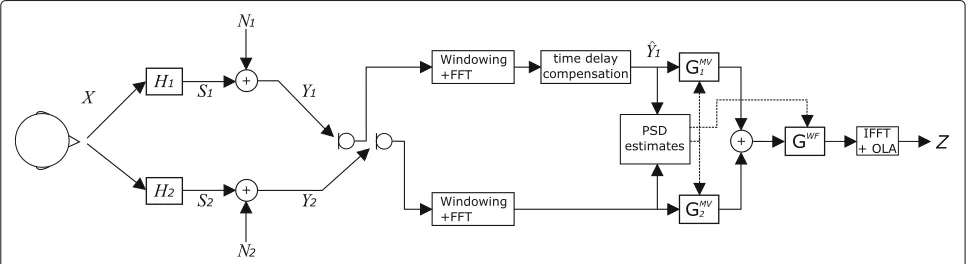
= YMV ·GWF. (46) This wind noise reduction algorithm is only applied for frequencies below a cutoff frequencyfc, because wind noise mostly contains low frequency components and the assumptions about the signal properties are only valid for low frequencies. Figure1shows the block diagram of the signal processing structure.
4 Simulation results
In the following, simulation results for the algorithm pro-posed in Section3are presented for wind noise in a car. For the signal measurements, a linear MEMS microphone
array in an endfire configuration was mounted above the sun visor at the driver seat position. To investigate vary-ing microphone distances, an array with four sensors was used. The microphone distances were 7.1, 14.3, and 21.4 mm.
The noise recordings and the speech recordings were done separately and mixed in the simulation. For the noise recordings, the driving speed was 100 km/h and both front windows at the driver side as well as the co-driver side were completely open to allow a turbulence airflow over the MEMS array. The speech signals for testing were four ITU speech signals convolved with the impulse responses, which were measured from the mouth reference point of an artificial head (HMS II.5 from HEAD acoustics) at the driver’s position to the MEMS array microphones.
For the simulations, a sampling ratefs = 16 kHz and an fast Fourier transform (FFT) size of 512 samples was used. The FFT shift was 128 samples, and each block was windowed before it was transformed into the frequency domain. The cutoff frequencyfcwas set to 1 kHz.
As quality measures, we consider the segmental signal-to-noise ratio (SSNR), the log spectral distance (LSD), as well as short-time objective intelligibility measure (STOI) as described in [37]. The STOI is a metric for speech intelligibility.
It should be noted that the SSNR and LSD mea-sures are calculated for the frequency region below the cutoff frequency fc since the frequency region above
fc is not affected by the proposed wind noise reduc-tion approach. Therefore, the signals are transformed back into the time domain and are low-pass filtered to calculate the SSNR and LSD values. The STOI is calculated over the complete frequency range with 15 third-octave bands.
The LSD measures the linear speech distortion and is calculated as the average logarithmic spectral distance of two PSDs. These are the signals under test, i.e., the speech component of the filtered output signal and the clean speech referenceX. The PSDs are calculated over all speech active blocks using an ideal voice activity detector.
For further details regarding the LSD calculation, we refer to [38].
The SSNR is calculated based on [39]. However, we cal-culate the SSNR by the ratio of the signal energy of the speech and the noise components in speech active frames as
SSNR= 1
K
K−1
l=0
10log10
Rl+M−1
k=Rl |˜s(k)|2 Rl+M−1
k=Rl |˜n(k)|2 35
−10 .
(47)
˜
s(k) andn˜(k)are the speech and noise components at the output of the dedicated noise reduction approach in the time domain. k is the time index, M is the frame length, R is the frame shift, and K is the total number of considered frames. The frame length was 512 samples, and the frame shift was 256 samples. The SSNR values are limited between−10 and 35 dB.
Car noise, which is also present in the microphone sig-nals, is not considered in our algorithm. Thus, the SSNR improvements in absolute value can be lower compared with measured noise signals which contain wind noise only.
4.1 Coherence properties
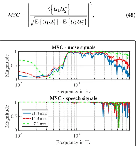
Figure 2 shows the results of the magnitude squared coherence calculation of speech and noise for varying microphone distances. The magnitude squared coherence for two signalsu1(k)andu2(k)is calculated as
MSC=
EU1U2∗
EU1U1∗
·EU2U2∗
2
, (48)
102 103
Frequency in Hz 0
0.5 1
Ma
g
nit
u
de
MSC - noise signals
102 103
Frequency in Hz 0
0.5 1
Ma
g
nit
u
de
MSC - speech signals
21.4 mm 14.3 mm 7.1 mm
Fig. 2Magnitude squared coherence for the noise signalsN1andN2
(top) as well as the speech signalsS1andS2(bottom) with different
microphone distances
where U1 andU2 denote the corresponding short-time spectra. The mathematical expectation values of the input signals are estimated by the Welch periodogram using recursive smoothing. A very high smoothing factor of 0.9995 was chosen to average over many signal frames. An MSC value close to one means the signals are highly cor-related, whereas a value close to zero indicates that the signals are uncorrelated.
As can be observed, the assumption that noise is uncor-related while speech is highly coruncor-related is fulfilled for frequencies below 600 Hz for all microphone distances, which justifies the assumptions made in Section3.
4.2 Beamformer output
In Table 1, the SSNR gain of the beamformer output is compared with a single microphone. This comparison is considered, because the approach in [17] suggest to switch from a differential microphone array to a single omnidi-rectional microphone if wind noise is detected. The SSNR of the single microphone is 2.14 dB. For further compar-ison, the results of the delay-and-sum beamformer YDS are shown, which is the summing of the aligned signals as described in (26) (and also proposed in [17] for combin-ing of wind noise-affected signals). Also, the output of a frequency bin selection (YFBS) approach as stated in (29) is examined. The noise estimates in (42), as derived in Section3.3, are used for the beamformer. Moreover, the ideal noise PSDs are used to get a benchmark. Since the noise signals where recorded separately for the simula-tions, the ideal noise PSDs are obtained by using the noise only signals for the PSD calculation. The PSDs are calcu-lated by the Welch periodogram using recursive smooth-ing. However, the short-time recursive PSD smoothing was omitted, because this achieved the best results due to the high non-stationarity of the wind noise.
As can be observed, all beamformer approaches are able to improve the SSNR in the considered frequency region compared with a single microphone, where all SNR gains are getting larger as the distance between the microphones is increased. It is interesting to see that the delay-and-sum approach YDS has the worst perfor-mance for all microphone distances, whereas the fre-quency bin selection approach shows results similar to
Table 1SSNR gain compared with single microphone for different beamformer outputs
Signal Microphone distance
7.1 mm 14.3 mm 21.4 mm
YDS(Eq. (26)) 0.96 dB 1.22 dB 1.58 dB
YFBS(Eq. (29)) 1.80 dB 2.25 dB 2.47 dB
YMV(Eq. (22)) (noise estimate) 1.77 dB 2.34 dB 2.80 dB
the MV beamformer. This indicates that the short-time PSDs at the microphones vary heavily. Comparing the performance with estimated noise PSDs with that of the beamformer with the actual noise PSDs, we observe that the results regarding the SSNR are similar, i.e., the PSD estimates are sufficiently accurate.
4.3 Post filter output
Now, the SSNR as well as the LSD for the complete MWF including the post filter (as derived in (46)) are examined. To compare the post filter of (43) with other approaches, a wind noise reduction filter by Franz et al. [20] that defines a filter function based on the magnitude squared coher-ence is used as a refercoher-ence. The proposed post filter in (43) as well as the post filter derived in [20] are applied to the beamformer outputYMV which uses the noise esti-mates. As can be seen in Table2, the SSNR can be further improved while keeping the speech distortion below 1 dB compared with the single microphone signalY1.
For the post filter comparison, the noise overestimation parameterμwas set to achieve a similar LSD value as the post filter in [20]. The short-time PSDs used for the post filter, as well as the calculated MSC needed for the filter design in [20], were recursively smoothed by the same fac-tor of 0.85 to make a fair comparison. As can be seen, both post filters are able to achieve the same noise reduction.
Table 2 also contains values for the STOI. The STOI is closely related to the percentage of correctly under-stood words averaged across a group of users. The maxi-mum STOI value is one and larger values indicate better speech intelligibility. The noisy speech signals are com-pared with the time domain signal of the clean speechX. It can be seen in Table2 that the STOI is increased for the beamformer output YMV compared with the single microphoneY1. The results indicate that additional post filtering improves the STOI, where the post filters obtain similar STOI values.
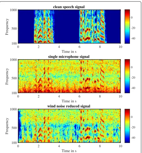
Figure3shows the spectrogram for the omnidirectional reference microphone, as well as the outputZof our pro-posed wind noise reduction algorithm with a microphone distance of 21.4 mm. It can be observed that the high energetic noise terms in the low frequencies are success-fully suppressed. Above 600 Hz the noise reduction is not as strong, i.e., the assumptions for the wind noise signal
Table 2Results for the post filter output for wind noise and driving noise
Signal SSNR gain LSD STOI
Y1 – 2.3 dB 0.799
YMV(Eq. (22)) 2.80 dB 2.2 dB 0.821
YMV(Eq. (22)) + post filter after [20] 5.43 dB 3.3 dB 0.825
Z(Eq. (46)),μ=6 5.44 dB 3.3 dB 0.826
Fig. 3Spectrogram for a single microphoneY1(middle) and the
output signalZfrom (46) (bottom)
properties with this noise recording are only valid for frequencies below 600 Hz (cf. Fig.2).
4.4 Wind noise only scenario
Finally, the wind noise reduction is considered in a sce-nario containing only wind noise and no driving noise. The SSNR of the single microphoneY1is 4.86 dB in this scenario. The results can be seen in Table3. Again, the beamformer output YMV with noise estimation is used with both post filter approaches as in Section 4.3. All parameters except for the overestimation parameter are the same. The table contains results for two different values of the overestimation parameter for the Wiener post filter in order to demonstrate the trade-off between speech distortion and noise reduction. Withμ = 8, the Wiener filter and the filter from [20] obtain similar perfor-mance values. Reducing the overestimation parameter to μ=1 also reduces the SNR gain, but results in better LSD and STOI values. Comparing the results with the gains in
Table 3Results for the post filter output in a scenario containing only wind noise
Signal SSNR gain LSD STOI
Y1 – 2.3 dB 0.896
YMV(Eq. (22)) 3.42 dB 2.3 dB 0.917
YMV(Eq. (22)) + post filter after [20] 9.18 dB 3.1 dB 0.900
Z(Eq. (46)),μ=8 9.34 dB 3.3 dB 0.906
Table2, the achieved SSNR values are higher due to the absence of the driving noise.
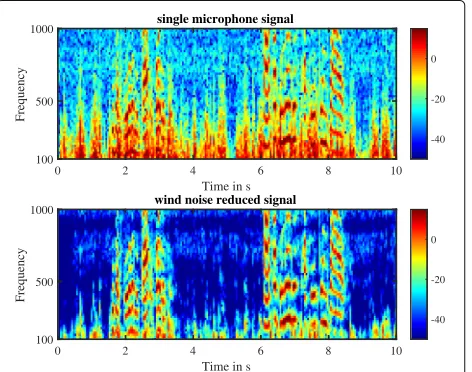
Figure 4 shows the spectrogram of the output Z for the wind noise only scenario. The noise is significantly reduced over a wide frequency range. Since the coherent driving noise terms are not present in this scenario, noise reduction can also be observed for frequencies above 600 Hz.
5 Conclusions
In this paper, a wind noise reduction approach for a com-pact endfire array was examined. Based on the decom-position of the MWF, a beamformer and a post filter were derived. Due to the known geometry of the MEMS microphone array in endfire configuration and knowl-edge about the position of the speech source, assumptions about the signal properties of the speech and wind noise components were made. The acquired estimates of the PSDs for the wind noise as well as the speech signals are used to design a beamformer as well as a post filter for wind noise reduction. The simulations based on noise recordings in a car environment show that a significant wind noise reduction is possible while keeping the speech distortion low.
Further investigations should be made to combine the proposed wind noise reduction approach with the reduc-tion of car noise. The driving noise is neglected in our study. The compact microphone array can be part of an array of more widely spaced microphones, where the spa-tial diversity of the sound field can be exploited for further noise reduction. Since the non-stationary noise terms are mostly reduced with the proposed approach, state-of-the-art noise estimation procedures can be chosen that rely on the assumption that the driving noise is only slowly varying.
Fig. 4Spectrogram for a single microphoneY1(top) and the output
signalZfrom (46) (bottom) in a wind noise only scenario
Wind noise-induced disruptions are a commonly known problem with differential beamforming, e.g., with the closely spaced microphone arrangements in hearing aids [17]. Hence, the proposed noise reduction approach may also be applicable for hearing aids.
Abbreviations
ATF: Acoustic transfer function; DS: Delay-and-sum; FFT: Fast Fourier transform; LSD: Log spectral distance; MEMS: Micro-electro-mechanical system; MSC: Magnitude squared coherence; MV: Minimum variance; MVDR: Minimum variance distortionless response; MWF: Multichannel Wiener filter; PSD: Power spectral density; SNR: Signal-to-noise-ratio; SSNR: Segmental
signal-to-noise-ratio; STOI: Short-time objective intelligibility measure
Acknowledgements
We thank the Daimler AG, Department Enabling Technologies for Communication, Ulm, for providing the measurement data.
Availability of data and materials
The measurement data was used by courtesy of Daimler AG. It is not available for public access.
Authors’ contributions
Both authors developed the idea of the proposed algorithm. JF initiated the theoretical description, while SG implemented the algorithm and refined it in the simulations. The simulations and a majority of the manuscript writing were done by SG, while JF supervised the simulations and helped in improving the text. Both authors read and approved the final manuscript.
Authors’ information
Simon Grimm (SG) is a member of the signal processing group at the Institute for System Dynamics at the HTWG Konstanz since 2014. His work is primarily concerned with the development of signal processing algorithms for multichannel noise reduction approaches in noisy acoustic environments. He received his B. Eng. in 2012 and his M. Eng. in 2014.
Dr. Jürgen Freudenberger (JF) is a professor at the HTWG Konstanz since 2006, where he is the head of the signal processing group at the Institute for System Dynamics. His work is primarily concerned with the development of algorithms in the field of signal processing and coding for reliable data transmission as well as efficient algorithm implementation for hardware and software.
Competing interests
The authors declare that they have no competing interests.
Publisher’s Note
Springer Nature remains neutral with regard to jurisdictional claims in published maps and institutional affiliations.
Received: 12 September 2017 Accepted: 9 July 2018
References
1. P Vary, R Martin,Digital Speech Transmission: Enhancement, Coding and Error Concealment. (Wiley, Chichester, 2006)
2. E Hänsler, G Schmidt,Acoustic Echo and Noise Control: A Practical Approach. (Wiley, New Jersey, 2004)
3. S Doclo, A Spriet, M Moonen, J Wouters, inSpeech Enhancement. Speech distortion weighted multichannel Wiener filtering techniques for noise reduction (Springer, Berlin, 2005). Chap. 9. https://doi.org/10.1007/3-540-27489-8_9
4. S Doclo, A Spriet, J Wouters, M Moonen, Frequency-domain criterion for the speech distortion weighted multichannel Wiener filter for robust noise reduction. Speech Comm.49(7-8), 636–656 (2007).https://doi.org/ 10.1016/j.specom.2007.02.001
6. T Matheja, M Buck, T Fingscheidt, A dynamic multi-channel speech enhancement system for distributed microphones in a car environment. EURASIP J. Adv. Signal Proc.2013(2013)
7. J Benesty, C Jingdong,Study and Design of Differential Microphone Arrays. (Springer, Berlin, 2013)
8. GW Elko,Differential microphone arrays. In: Y Huang, J Benesty. (eds) Audio Signal Processing for Next-Generation Multimedia Communication System. (Springer, Boston, 2004)
9. H Teutsch, GW Elko, inInternational Workshop on Acoustic Signal Enhancement. First- and second-order adaptive differential microphone arrays, (2001), pp. 35–38
10. J Benesty, M Souden, Y Huang, A perspective on differential microphone arrays in the context of noise reduction. IEEE Trans. Audio, Speech, Lang. Process.20(2), 699–704 (2012).https://doi.org/10.1109/TASL.2011. 2163396
11. GW Elko, Microphone array systems for hands-free telecommunication. Speech Commun.20(3), 229–240 (1996). https://doi.org/10.1016/S0167-6393(96)00057-X. Acoustic Echo Control and Speech Enhancement Techniques
12. M Turqueti, J Saniie, E Oruklu, in2010 53rd IEEE International Midwest Symposium on Circuits and Systems. MEMS acoustic array embedded in an FPGA based data acquisition and signal processing system, (2010), pp. 1161–1164.https://doi.org/10.1109/MWSCAS.2010.5548866 13. I Hafizovic, C-IC Nilsen, M Kjølerbakken, V Jahr, Design and
implementation of a MEMS microphone array system for real-time speech acquisition. Appl. Acoust.73(2), 132–143 (2012).https://doi.org/ 10.1016/j.apacoust.2011.07.009
14. J Tiete, F Domí-nguez, Bd Silva, L Segers, K Steenhaut, A Touhafi, Soundcompass: a distributed mems microphone array-based sensor for sound source localization. Sensors.14(2), 1918–1949 (2014).https://doi. org/10.3390/s140201918
15. G Elko, Small directional microelectromechanical systems (MEMS) microphone arrays. Proc. Meet. Acoust.19(1), 030033 (2013).https://doi. org/10.1121/1.4799608.http://asa.scitation.org/doi/pdf/10.1121/1. 4799608
16. A Palla, L Fanucci, R Sannino, M Settin, in2015 10th International Conference on Design Technology of Integrated Systems in Nanoscale Era (DTIS). Wearable speech enhancement system based on MEMS microphone array for disabled people, (2015), pp. 1–5.https://doi.org/10. 1109/DTIS.2015.7127384
17. JW Kates,Digital Hearing Aids. (Plural Publishing, San Diego, 2008) 18. S Bradley, T Wu, S von Hünerbein, J Backman, inAudio Engineering Society
Convention 114. The mechanisms creating wind noise in microphones, (2003)
19. DK Wilson, MJ White, Discrimination of wind noise and sound waves by their contrasting spatial and temporal properties. Acta Acustica United Acustica.96(96), 991–1002 (2010)
20. S Franz, J Blitzer, inInternational Workshop on Acoustic Signal Enhancement (IWAENC). Multi-channel algorithms for wind noise reduction and signal compensation in binaural hearing aids, (2010)
21. CM Nelke, P Vary, inInternational Workshop on Acoustic Signal Enhancement (IWAENC). Measurement, analysis and simulation of wind noise signals for mobile communication devices, (2014)
22. CM Nelke, N Chatlani, C Beaugeant, P Vary, inIEEE International Conference on Acoustic, Speech and Signal Processing (ICASSP). Single microphone wind noise PSD estimation using signal centroids, (2014)
23. S Kuroiwa, Y Mori, S Tsuge, M Takashina, F Ren, inInternational Conference on Communication Technology. Wind noise reduction method for speech recording using multiple noise templates and observed spectrum fine structure, (2006)
24. B King, L Atlas, inProceedings of International Workshop on Acoustic Signal Enhancement (IWAENC). Coherent modulation comb filtering for enhancing speech in wind noise, (2008)
25. E Nemer, W Leblanc, inProceedings of IEEE Workshop on Applications of Signal Processing to Audio and Acoustics (WASPAA). Single-microphone wind noise reduction by adaptive postfiltering, (2009)
26. C Hofman, T Wolff, M Buck, T Haulik, W Kellermann, inProceedings of International Workshop on Acoustic Signal Enhancement (IWAENC). A morphological approach to single-channel wind-noise suppression, (2012)
27. CM Nelke, N Nawroth, M Jeub, C Beaugeant, P Vary, inProceedings of European Signal Processing Conference (EUSIPCO). Single microphone wind noise reduction using techniques of artificial bandwidth extension, (2012) 28. CM Nelke, P Vary, inProceedings of Speech Communications - 11. ITG
Symposium. Dual microphone wind noise reduction by exploiting the complex coherence, (2014)
29. P Thüne, G Enzner, inITG Conference on Speech Communication. Maximum-likelihood approach to adaptive multichannel-Wiener postfiltering for wind-noise reduction, (2016)
30. KU Simmer, J Bitzer, C Marro, inMicrophone Arrays: Signal Processing Techniques and Applications, ed. by MS Brandstein. Post-filtering techniques (Springer, Berlin Heidelberg, 2001), pp. 39–60 31. KU Simmer, J Bitzer, inJahrestagung für Akustik (DAGA), Aachen.
Multi-microphone noise reduction — theoretical optimum and practical realization, (2003)
32. GM Corcos, The structure of the turbulent pressure field in
boundary-layer flows. J. Fluid Mech.18(3), 353–378 (1964).https://doi. org/10.1017/S002211206400026X
33. R Martin, Noise power spectral density estimation based on optimal smoothing and minimum statistics. IEEE Trans. Speech Audio Process.9, 504–512 (2001)
34. J Freudenberger, S Stenzel, B Venditti, inProc. European Signal Processing Conference (EUSIPCO), Glasgow. Spectral combining for microphone diversity systems, (2009), pp. 854–858
35. J Freudenberger, S Stenzel, inIEEE Workshop on Statistical Sig. Proc. (SSP). Time-frequency dependent voice activity detection based on a simple threshold test (IEEE, Nice, 2011)
36. R Zelinski, inICASSP-88., International Conference on Acoustics, Speech, and Signal Processing. A microphone array with adaptive post-filtering for noise reduction in reverberant rooms, (1988), pp. 2578–25815.https://doi. org/10.1109/ICASSP.1988.197172
37. CH Taal, RC Hendriks, R Heusdens, J Jensen, An algorithm for intelligibility prediction of time-frequency weighted noisy speech. IEEE Trans. Audio Speech Lang. Process.19(7), 2125–2136 (2011).https://doi.org/10.1109/ TASL.2011.2114881
38. PA Naylor, ND Gaubitch,Speech Dereverberation, 1st edn.(Springer, London, 2010)