DOI: 10.5958/2230-732X.2017.00039.0 ©2017New Delhi Publishers. All rights reserved
AgrIculturAl EngInEErIng
Modification and Testing of Manually Operated Rocker
Sprayer
Saptashish Deb
1, Sonu Kumar
2, K.R. Jolvis Pou
3*, Sanat Das
1and Mrinmoy Biswas
2 1College of Agricultural Engineering and Post Harvest Technology, Central Agricultural University, Gangtok, India 2North Eastern Regional Institute of Science and Technology, Itanagar, India3Department of Agricultural Engineering, School of Technology, Assam University, Silchar, India
*Correspondence author: jolvispou@gmail.com
Paper No. 584 Received: 19-1-2017 Accepted: 18-5-2017
Abstract
This study was done to modify the existing rocker sprayer. Manually operated lever was replaced with an electric motor and the speed of the motor was regulated by a voltage regulator. For determining the
power requirement, the speed of the manually operated sprayer was regulated by subjects’ analysis and
was found to work with an average speed of 74 rpm of the piston movement. Modification was done to get the same boom length of the sprayer. The power requirement of the sprayer was determined as 0.016 hp, but 0.25 hp motor was used due to market’s unavailability. A model of the slider crank mechanism was developed to study the effect of connecting rod length, crank angle and rpm on the piston displacement and the linear velocity for the modification of the rocker sprayer. It was found that, the piston displacement and the velocity decreases with an increase in the length of the connecting rod and vice versa. Piston linear velocity was found to be maximum at two crank angles in the range of 90-120° and 260-280°. The weight of the implement was about 4.75 kg. The sufficient pressure of 80-90 psi was obtained for the purpose of spraying, as found in the existing manually operated sprayer. The slider-crank mechanism is useful for the development of the power operated sprayer and for other agricultural machineries.
Highlights
• With the increase of the length of the connecting rod, the piston displacement and the piston linear velocity decreases and vice versa
• Piston linear velocity was found to be maximum at two crank angles in the range of 90-120° and 260-280°
• Modification of manually operated rocker sprayer
Keywords: Sprayer,piston, crank, piston displacement, piston linear velocity
India is set to be an agricultural based country. Approximately 75% of the total population of India is directly or indirectly dependent on farming. Sikkim is one of the Northeast hilly states of India. Subtropical to temperate climate of Sikkim, fertile soil and abundant rainfall gives the state an opportunity to grow variety of vegetable crops, flowers, fruits, spices, and aromatic plants[1].
Farmers have been and still are following different methods and equipments of spraying for ages.
portable sprayers use electric motor so that they can be easily taken to the spraying sites. In Sikkim, power operated sprayer is suitable for spraying in orchards, horticulture crops, rubber vineyards and field crops. Tall trees up to a height of 20 feet can be sprayed with these types of sprayers[2]. In Sikkim,
agricultural workers and cultivators are around 56.36% of the total workers. Female workers are around 1.5 times of male workers[3-4]. In ergonomics
point of view, females are weaker than male[5].
During field preparation to harvesting operations, most of the tools used are handmade and manually operated tools. These activities involve a lot of drudgery. Therefore, keeping into consideration that Sikkim is a completely electrified state[6] the current
studies focused on the development of a power operated model of the slider-crank mechanism and the effect of different connecting rod lengths on piston displacement, velocity and pressure.
MAtErIAls AnD MEthODs
The experiment was carried out in the Farm Power Laboratory, Department of Farm Power and Machinery, College of Agricultural Engineering and Post-Harvest Technology, Central Agricultural University, Gangtok, Sikkim, which is located between 88°03’40” to 88°57’19” East longitude and 27°03’47” to 28°07’34” North latitude.
root of the symptom of model
Sikkim is one of the Northeast hilly states of India, having favourable climate for producing horticulture fruits such as orange and guava[1]. These
fruits are cultivated for commercial purpose on hilly terrains. Organic based pesticides, insecticides etc. are usually sprayed by means of the manually operated sprayers[7-9] and most of time it is run by
the female workers.
The height of the orange trees range from 10 to 25 feet whereas the height (stature) of the female workers range from 4.86 to 5.15 feet[10]. The use of
manually operated sprayer may cause early fatigue and musculoskeletal disorder due to repetitive task[11-12]. For solving the problem of repetitive
manual pumping with the lever at the speed of 70-110 rpm, the power operated sprayer can be a better alternative for the spraying of the orchard trees or the agricultural field.
Alternative device
To overcome the difficulties of the female workers with the existing models, and to reduce the drudgery and musculoskeletal disorder problem that occurs because of the manual operation of the rocker sprayer,[13] a modified model was developed
for the effective operation by using motor with a speed controlling device. In this modified model, the hand operated handle is replaced with a motor attached with eccentric disc through which connecting rod of piston is connected to provide reciprocating motion with the speed in the range of 70-110 rpm. This device is powered by electrical energy which is available at any place of Sikkim because Sikkim claims to be a 100% electrified state[6]. It can also be operated either by a battery
or by solar panels. The specification of the existing rocker sprayer is shown in Table 1.
table 1: Description of the existing rocker sprayer
Pump type Piston
Pump material Brass
Maximum working pressure 80-90 psi
Hose length 25-75 feet
Spray system Lance with cone brass nozzle and hi-jet gun
Minimum discharge rate 1200 cc/min
Power requirement of the rocker sprayer
In order to make the crank to rotate fully, the condition L > R+E must be satisfied, where, R is the crank length, L is the length of the connecting rod and E is the offset of the slider[14-16]. A slider crank is
a RRRP type of mechanism which has three revolute joints and one prismatic joint.
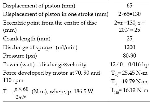
table 2: Specification of the sprayer
Displacement of piston (mm) 65
Displacement of piston in one stroke (mm) 2×65=130
Eccentric point from the centre of disc
(mm) 2πr =130, r = 20.7 ≈ 25
Crank length (mm) 25
Discharge of sprayer (ml/min) 1200
Pressure (psi) 80-90
Power (watt) = discharge×velocity 12.40 = 0.016 hp Force developed by motor at 70, 90 and
110 rpm T = 60
2 p
N π
× (N-m), where, p=186.5 W
T70= 25.45 N-m
T90= 19.79 N-m
Fig. 1: Measurement of the pumping speed Fig. 2: Manually operated slider crank mechanism
Fig. 4: 2-D view with the dimension of the spraying system
Fig. 5: 3-D view of the spraying system
Fig. 3: Power operated slider crank mechanism
Fig. 6: Piston displacement versus crank angle, showing the comparison of plots for the connecting rod lengths of 350,
For determining the power requirement, a specific speed of the sprayer was measured as shown in Fig. 1. It involved 10 subjects and speed ranges from 55-91 rpm. The average speed was calculated as 74 rpm as shown in Table 3.
table 3: Pumping speed of sprayer
Female subject speed (rpm) Average (rpm)
1 65
74
2 55
3 75
4 60
5 89
6 73
7 82
8 69
9 78
10 91
After calculating speed, power requirement of sprayer was calculated to select the motor power.
Description of the developed model
The model was developed at the College of Agricultural Engineering and Post-Harvest Technology, Central Agricultural University, Gangtok, Sikkim. The model consists of one mild still base plate, two supporting stands, a circular scale, a linear scale, and a wheel to give rotary motion to the crank manually as represented in Fig. 2. Rotary motion from the wheel to crank is transferred through the shaft. The crank, connecting rod and the piston are connected with nut and bolt. All the parts in the model are made up of mild steel, except the cylinder and boost which are made up of galvanized iron (GI) pipe. The weight of the model was about 4.75 kg. Four different lengths of the connecting rod (350, 360, 370 and 390 mm) were considered to study the model.
Fig. 7: Piston velocity versus crank angle, showing the comparison of plots for connecting rod length of 350 mm and
angular speed of 70 rpm, 90 rpm, and 110 rpm
Fig. 8: Piston velocity versus crank angle, showing the comparison of plots for connecting rod length of 360 mm and
angular speed of 70 rpm, 90 rpm, and 110 rpm
Fig. 9: Piston velocity versus crank angle, showing the comparison of plots for connecting rod length of 370 mm and
angular speed of 70 rpm, 90 rpm, and 110 rpm
Fig. 10: Piston velocity versus Crank angle, showing the comparison of plots for connecting rod length of 390 mm and
slider displacement analysis
To find out the slider displacement against the crank angle by changing the length of the connecting rod, at first the crank angle was set at 0° with the help of a pointer and the initial position of the slider was marked. Connecting rod length of 350, 360, 370, and 390 mm were considered to determine the slider displacement for every 10° of the crank rotation.
slider velocity analysis
A motor of 0.25 hp was used to run the developed model as shown in Fig. 3. Crank rpm of 70, 90, and 110 were considered for different lengths of connecting rod. The slider linear velocity was calculated using Eq. 1.
(
)
(
)
2 N X V T π θ × =
× mm/sec …(1)
Where,
V = Piston linear velocity (mm/sec) N = No. of stroke
T = Time taken for N revolution (sec) θ = Crank angle (radian)
X= Crank slider displacement for θ radian revolution (mm)
Modified sprayer
Modification of the rocker sprayer was done with the incorporation of the designed developed model of the slider crank mechanism which is power operated. The 2-dimensional (2-D) view along with the 3-dimensional (3-D) view of the modified rocker sprayer pumping system were as shown in Fig. 4 and 5, respectively.
rEsults AnD DIscussIOn
The piston displacement was observed at every 10° of crank angle for different lengths of the connecting rod (350, 360, 370, and 390 mm). The piston displacement was found to vary between 1-10.5, 1-9, 1-8.5, and 1-8 mm for 350, 360, 370, and 390 mm of the connecting rod, respectively. However, no definite trend was observed in the displacement of the piston. Theoretical analysis of the piston linear velocity for different angular velocity of crank was calculated for different lengths of the connecting rod at every 10° crank angle and compared with
the experimental results obtained. The graph plotted between piston displacement and crank angle (Fig. 6) showed that, if the length of the connecting rod was minimum then the piston displacement was found to be maximum and vice versa. For all the connecting rod lengths, the maximum piston displacement was observed at two different crank angles. As observed in Fig. 7, the maximum piston displacement of 10.5 mm was obtained at 110° and 280° of crank angle for 350 mm of connecting rod. Similarly, for 360, 370, and 390 mm of connecting rod lengths, the highest piston displacement were observed at 90° and 270°, 90° and 260°, and 120° and 270°, respectively, at which the maximum piston displacement of 9, 8.5, and 8 mm were measured, respectively.
As evident, the piston linear velocity increases with the increased of crank rpm. As shown in Fig. 7, the highest piston linear velocity of 693 mm/sec was observed at 110 rpm at 110° and 280° of crank angle for 350 mm of the connecting rod length, and 567 and 441 mm/sec were found at 90 and 70 rpm at 110° and 280° of the crank angle. For 360 mm length of the connecting rod at 90° and 270° of crank angle, the piston linear velocity were determined as 378, 486, and 594 mm/sec at 70, 90, and 110 rpm, respectively, as represented in Fig. 8. Similarly, for the connecting rod length of 370 mm at 90° and 260° angle, the linear velocity of piston were found to be as 357, 459, and 561 mm/sec, respectively, as shown in Fig. 9. In case of 390 mm of connecting rod at 120° and 270°, as observed in Fig. 10, at 70, 90, and 110 rpm, the linear velocity of piston were recorded as 336, 432, and 528 mm/sec, respectively. All the maximum piston displacements were found in between 90˚ to 120˚ and 260˚ to 280˚ of crank angle. However, no definite trend was observed in the displacement as well as the velocity of the piston. It was found that the pressure developed in the modified sprayer was in the range of 80-90 psi, which is sufficient for spraying purposes as developed in the manually operated rocker sprayer.
cOnclusIOn
hp but due to market unavailability, 0.25 hp motor was used. The speed of the manually operated sprayer was estimated by the subjects’ survey and was found to work with an average speed of 74 rpm of the piston movement. It was done for getting the same boom length of the sprayer. The weight of the implement was about 4.75 kg. It was found that piston displacement and the linear velocity increases with a decrease in the length of the connecting rod and vice versa. In all the cases, piston linear velocity was found to be higher at two crank angles in the range of 90-120° and 260-280°. The sufficient pressure of 80-90 psi was obtained for the spraying purposes as found in the existing manually operated sprayer.
rEFErEncEs
Afzal, A. 2004. Fatigue behaviour and life predictions of
forged steel and power metal connecting rods, Thesis,
Master of Science, University of Toledo.
AICRP on ESA Progress report of Sikkim 2012. Sixth workshop, CIAE, Bhopal.
Biswas, R.K. and Majumdar, D. 2013. Baseline data on area,
production and productivity of horticulture crops in
Sikkim. Agro Economic Research Centre, Visva-Bharati, Santiniketan.
Dewangan, K.N., Owary, C. and Datta, R.K. 2009. Anthropometry of male agricultural workers of
north-eastern India and its use in design of agricultural tools and equipment, International Journal of Industrial Ergonomics 40: 560-573.
Ha, J.L., Fung, R.F., Chen, K.Y. and Hsien, S.C. 2006. Dynamic modelling and identification of a slider-crank mechanism. Journal of Sound and Vibration289: 1019-1044.
Indian standard methods of test for manually-operated sprayers.1994. Bureau of Indian Standards, New Delhi. Retrieved from https://law.resource.org/pub/in/bis/S06/ is.10134.1994.pdf.
Kolhe, S.L., Gajbhiye, N.B. and Deshmukh, V.B. 2014.
Eco-friendly mechanically operated multipurpose spray
pump. International Journal of Research in Advent Technology 2: 1-5.
Koser, K. 2004. A slider-crank mechanism based robot arm performance and dynamic analysis. Mechanical Machine Theory39: 169-182.
Ng, Y.G., Tamrin, S.B., Yik, W.M., Yusoff, I.S. and Mori, I. 2014. The Prevalence of musculoskeletal disorder and
association with productivity loss: A preliminary study among labour intensive manual harvesting activities in oil palm plantation, Industrial Health52: 78–85.
Ranjbarkohan, M., Rakesh M., Hoseini, A.H., Kheiralipour, K. and Mohammad Reza Asadi, M.R. 2010. Kinematics and kinetic analysis of the slider-crank mechanism in Otto linear four cylinders Z24 engine. Journal of Mechanical Engineering Research 3: 85-95.
Rattan, S.S. 2009. Theory of Machines, Third Edition. Tata McGraw Hill Education Private Limited.
Raut, L.P. Jaiswal, S.B. and Mohite, N.Y. 2013. Design,
development and fabrication of agricultural pesticides
sprayer with weeder. International Journal of Applied Research and Studies, 2: 1-8.
Salvendy, G. 1997. Handbook of Human Factors and Ergonomics, Fourth Edition. John Wiley & Sons, Inc. New York.
Sikkim development report. 2008. Planning Commission, Government of India. Academic Foundation, New Delhi. Statistical profile on women labours. 2014. Labour Bureau,
Ministry of Labour and Employment, Government of India. Retrieved from http://labourbureau.nic.in/ Statistical_Profile_2012_13.pdf.