Available Online at www.ijpret.com
365
INTERNATIONAL JOURNAL OF PURE AND
APPLIED RESEARCH IN ENGINEERING AND
TECHNOLOGY
A PATH FOR HORIZING YOUR INNOVATIVE WORK
SOFTWARE FILTERING TECHNIQUE TO OVERCOME NOISE
ISSUES IN CAPACITIVE TOUCH SCREEN
PROF. P. B. NIRANJANE1, MISS. BHAGYASHRI L. AGASHE2
1. Asst. Professor, Dept. Of Computer Science And Engg, Babasaheb Naik College Of Engg, Pusad (INDIA).
2. M.E. 2nd Sem. Student, Dept. of Computer Science And Engg, Babasaheb Naik College Of Engg, Pusad, INDIA.
Accepted Date: 15/02/2014 ; Published Date: 01/04/2014
\
Abstract: This paper reviews Capacitive touch screen technology. Basically paper introduces basic working of capacitive touch screen technology and relates to a method of filtering noise in capacitive touch panel. Touchscreen devices that use that technology have become widely popular over the past few years. capacitive touch sensors are widely used in consumer products like MP3 players, mobile phones and other portable devices. More and more the technology is utilized in further application fields such as household appliances as well as automotive and industrial applications. Touch-screen technologies, which are at the forefront of a design revolution in user interfaces, are coming into the spotlight. Lately, capacitive-type touchscreens have been widely adopted in high-end mobile applications mainly because they offer multi- and soft-touch features together with higher durability and superior light transmittance over resistive-type touch-screens.
Keywords: Capacitive touch screen, Capacitance, Noise, SNR, Software filtering
Corresponding Author: PROF. P. B. NIRANJANE
Access Online On:
www.ijpret.com
How to Cite This Article:
Available Online at www.ijpret.com
366 INTRODUCTION
A touchscreen is an electronic visual display that can detect the presence and location of a touch within the display area. The touch panels themselves are based around four basic screen technologies: Resistive, Capacitive, Surface Acoustical Wave (SAW) and Infrared (IR). Capacitive measurement methods have been used for a long time in many applications to determine physical values like distance, pressure, liquid level, acceleration etc. Capacitive touch sensors are just another application field.. Capacitive touch screens have become the dominant user interface technology for smartphones and tablet computers. Product designers who want to include a capacitive touch screen in their device need to satisfy a large number of requirements simultaneously. When these requirements conflict with each other, designers have always had to endure painful trade-offs in the quality of their design: “Should I compromise on the responsiveness of the screen to improve robustness to noise?”. It is possible to almost completely remove the effects of display noise using only software filters, without the need for display synchronization or high voltages
II. CAPACITIVE TOUCH SCREENS
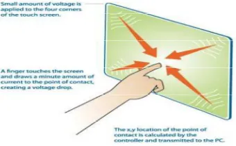
A capacitive touch screen panel is coated with a material that stores electrical charges. When the panel is touched, a small amount of charge is drawn to the point of contact. Circuits located at each corner of the panel measure the charge and send the information to the controller for processing
Available Online at www.ijpret.com
367 The simplest form of a capacitor consists of two conductors, e.g. two metal plates, separated by an insulator. [4]When a touch occurs, the capacitance at the touch position changes, usually around 10 fF.
The following formula shows the parameters which influence capacitance[3]:
C = ε (A / d)
Ε = ε0 * εr
Where C is the capacitance
εr is the relative permittivity, also called dielectric constant, of the insulating material between the plates.
ε0 is the permittivity of free space (8.854x10⁻¹² F/m).
A is the area of the plates.
d is the distance between the plates.
relative permittivity εr
air/vacuum: ε=1 PE: ε=2 wood: ε=3
ABS: ε=4 glass: ε=7 water:ε=80
The larger the area of the plates, the larger is the capacitance. The smaller the distance between the two plates, the higher is the capacitance. The insulating material determines the dielectric constant.
The electrode of a touch sensor represents one plate of such a capacitor. The corresponding 2nd plate is represented by the environment of the sensor electrode (to form a parasitic capacitor C0) and another conductive object, like a human finger for example (to form touch capacitor CT).
Available Online at www.ijpret.com
368 Fig 2:Touch Sensor Principle: untouched sensor pad with parasitic capacitance C0, touched sensor pad with additional touch capacitance CT [3]
Considering the formula above, one can see that a bigger pad and a thinner overlaying cover material, leads to a bigger touch capacitance CT and as a result, a bigger capacitance difference between touched and untouched sensor pad. In other words, the size of the electrode and the covering material influence the sensitivity of the sensor.
III . TYPES OF CAPACITIVE TOUCHSCREEN
It is divided into two broad categories as follows:
A) SURFACE CAPACITIVE TECHNOLOGY
In this technology, only one side of the insulator is coated with a conductive layer. A small voltage is applied to the layer, resulting in a uniform electrostatic field. When a conductor, such as a human finger, touches the uncoated surface, a capacitor is dynamically formed. The sensor's controller can determine the location of the touch indirectly from the change in the capacitance as measured from the four corners of the panel.
Available Online at www.ijpret.com
369 B) PROJECTED CAPACITIVE TECHNOLOGY
Projected Capacitive Touch (PCT) technology is a capacitive technology which permits more accurate and flexible operation, by etching the conductive layer. An X-Y grid is formed either by etching a single layer to form a grid pattern of electrodes, or by etching two separate, perpendicular layers of conductive material with parallel lines or tracks to form the grid. A finger on a grid of conductive traces changes the capacitance of the nearest traces. This change in trace capacitance is measured and finger position is computed. The use of an X-Y grid permits a higher resolution than resistive technology.
Fig 4- Projected capacitive technology[1]
There are two main types of sensing methods, self-capacitance and mutual capacitance
1) SELF-CAPACITANCE
Available Online at www.ijpret.com
370 Fig 5. How Self Capacitance Works[6].
2) MUTUAL CAPACITANCE
Mutual capacitance is the intentional or unintentional capacitance between two "charge holding objects." Projected capacitance touch screens intentionally create mutual capacitance between elements of columns and rows in the vicinity where each intersect the other. This allows the system electronics to measure each node (intersection) individually to detect multiple touches on the screen during one screen scan. When a finger touches near an intersection, some of the mutual capacitance between the row and column is coupled to the finger which reduce the capacitance at the intersection as measured by the consystem electronics. This reduced capacitance crosses the "touch threshold" set by the electronics indicating a touch has occurred.
Available Online at www.ijpret.com
371 Fig. 7 demonstrates the difference in the basic principles of self and mutual capacitance touch screens. stands for the background capacitance or the capacitance without a touch and stands for the capacitance induced by the presence of a finger. The intersections of each row and column produce a unique touch coordinate. By measuring each intersection individually, the touch screen controller is able to detect an unlimited number of touches unambiguously.
Fig. 7. Capacitance change in the presence of a finger. (a) Self-capacitance screen. (b) Mutual capacitance screen.[5]
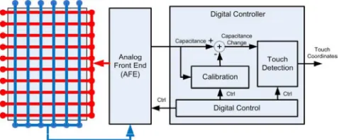
Fig. 8 shows the block diagram of a typical mutual capacitance touch screen system. The row electrodes are configured as the driving lines and column electrodes as sensing lines. The analog front end (AFE) is responsible for driving and measuring, the capacitance sensors and then converting the outputs to digital vectors which are further processed by a digital controller.
Fig. 8. Block diagram of a typical mutual capacitance touch screen system[5].
The calibration module in the digital controller extracts the capacitance introduced by finger touches by removing the background capacitance. The touch detection module locates the coordinates of touches by searching the peaks in the foreground capacitance.
IV. NOISE
Available Online at www.ijpret.com
372 described as a summation of unwanted or disturbing energy from natural and man-made sources. Some examples of noise include power supply noise, Wi-Fi transmitters, mobile phone transmitter, and environmental conditions like humidity and temperature changes.
Capacitive touch panel is sensitive to electrical source noise, RF noise and LCD noise.
A) The electrical source noise could be classified into power frequency noise (50/60 HZ) and power switch noise[2].
B) RF noise is another noise source of touch panel system. Generally, a frequency of more than 1 GHZ Will not disturb the touch panel system because such high frequency signal Will be immediately attenuated by circuits.
C) LCD noise becomes more and more important concern. Modern design tries to eliminate the thickness by reducing the distance between the touch panel and LCD or by eliminating the thickness of the touch panel itself. The frequency of LCD line drive signal is about tens of kHZ, which will disturb normal scan frequency.
The capacitive touch panel noise has the following characteristics[2]:
Definiteness: Some of the noise is definite once the system is built. For example, the power source noise including working frequency noise and power switch noise is closely related to the power switch and is determined by power switch.
Duration Is Short: The frequency of power switch noise is not high (tens of kHZ), and the duration is very short, only several micro seconds. During the cycle of noise signal, the noise only lasts for a very short time.
Great care is needed in touch screen applications to prevent a noisy environment from detracting from the high performance of the measurement system.
There are number of technologies and techniques available for improving robustness[7]:
Auto-tuning - Another innovative method evolved recently in the industry are real-time compensation algorithms that automatically determine the changing noise level in the system to differentiate a real finger touch from noise. The tradeoff to this approach is the need for additional processing capacity to implement the algorithm.
Available Online at www.ijpret.com
373 tuning takes some amount of time to learn to make sure the device is perfectly tuned for the end application.
Filters – Filters are the most commonly used method to suppress noise in a system. Capacitive sensing controllers incorporate a hardware filter, a firmware filter, or both, depending upon the application’s requirements and capabilities.
Compensation algorithms –Baseline compensation can be used to overcome changes in noise affecting CF. i.e. when noise occurs in a system, the device compensates to adjust the baseline (reference level). The noise threshold is thus automatically adjusted so as to keep most of the noise below noise threshold. This method is very effective for low frequency noise due to environmental changes.
Overcoming Qualification Testing Requirements – In this case, noise can be above the finger threshold in some case if best practices are not completely followed, making it hard to distinguish noise from an actual signal. This is because during qualification testing, high amount of noise is injected to test the system for robustness. Algorithms are available which can identify a specific signature in the noise pattern. The signature of this specific noise pattern is then rejected, leaving behind only the signal from finger touch and thus avoiding false presses.
V. SIGNAL-TO-NOISE RATIO
In capacitive touchscreens, the signal in SNR is the measured amount of change in mutual capacitance as a direct result of finger capacitance. In order to understand how hardware and software changes affect the system, it is necessary to have a way of measuring the signal’s current performance. Sensitivity, or the amount that the system shifts, is not a sufficient measurement to define if a system is stable[8].
One of the easiest ways to determine how stable a system is, or how much the system is affected by noise, is to look at its Signal-to-Noise Ratio (SNR). Just as it sounds, this is a way of measuring how strong the signal is when compared to unwanted disturbances of noise. For the purpose of this application note, the SNR formula being used is defined as:
Available Online at www.ijpret.com
374 Where:
µU is the unpressed average
µP is the pressed average
σ is the unpressed standard deviation
The numerator of the equation is the amount that the system will shift when pressed or the ‘signal’. The denominator is a measure of how much the noise is able to affect the readings. Using these as a ratio, a single number can be used to describe the quality of the sensor’s signal by answering the question: How much shift do you require compared to the amount of noise you are trying to avoid?.If conducted noise is present on the system, the SNR will change when the sensor is pressed versus released. It may also change based on the frequency of the injected noise.
VI. SOFTWARE FILTERING
Many different software filtering algorithms can be implemented to enhance the quality of reported touch positions. Software filtering, however, can sometimes be a trade off with the controller's code space, RAM space, and the time required to resolve touch events on the sensor. Filters are algorithms that take an input signal and output a modified version of the signal. The function it performs is based on the type of filter it is. The bandwidth of a filter also plays a large role in how it performs. From a firmware perspective, the function of the filter is defined in the code structure and operations that are performed. The bandwidth is usually set by constants in the implementation that determine what number a value should be divided by, how many times to bit-shift left or right, and what coefficient should be used to multiply the result by. With filters, there is a trade-off between noise reduction and response time delay. This trade-off can be visualized in the bandwidth of the filter as shown in fig 9.
Available Online at www.ijpret.com
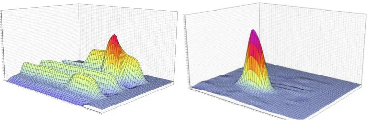
375 Software Filtering Enabled
Fig 10 : Two plots of raw data from a touch-on-lens sensor laminated to an ACVCOM display that outputs about 3V of peak-to-peak noise. A single finger is touching the sensor. On the left, software filtering is disabled, leading to a low signal-to-noise ratio. On the right, software filtering is enabled.
If the filter’s bandwidth is narrow, less noise will be able to pass through, but it may take a long time for the filter to follow the signal. On the other hand, if the filter’s bandwidth is wide, more noise will be able to pass through, but it will follow the signal more closely. Combining multiple filters can allow the designer to get the benefits of each while limiting the negative impact.
There are three types of filters that are commonly used in m Touch sensing solution applications. More filters could easily be added to this list and may be more appropriate for a specific application, but these have been chosen because most designs will be able to use
one or more of them.
The varius filter types are:
A) SLEW RATE LIMITER
Used as the first input filter on new incoming samples to reject impulse noise and smooth the signal. Implemented in the acquisition routine.
B) L-Point Running Average
Used to create a slow-updating (high time constant) baseline (“average”) for each sensor as a reference point during decoding. Allows the system to track environmental changes such as temperature and humidity. Implemented in the filtering routine.
Software Filtering Disabled
Available Online at www.ijpret.com
376 C) Low Pass Butterworth
Used to reject white noise on the sensor readings while still maintaining a fast response time (low time constant).
Implemented on the ‘reading’ variable in the filtering routine before sending it to the decoding algorithm.
D) FIR FILTERS VS. IIR FILTERS[8]
Finite-Impulse Response (FIR) filters take a fixed number of previous inputs and use them to create the next output.
Finite-Impulse Response Filter Benefits:
• Simple implementations
• Better filter stability
• Fewer concerns about integer precision
Infinite-Impulse Response (IIR) filters take the input and use it in combination with the previous output of the filter to determine the next filter output.
Infinite-Impulse Response Filter Benefits:
Low memory requirements
Low processing requirements
Ultimately, both filter types can be useful to an application. For capacitive touch systems, IIR filters can be used for slowly-updating environmental baselines. The filter should be designed so that it can handle impulse noise without becoming unstable. FIR filters can be used for quickly-updating sensor variables like the current reading. Infinite Impulse Response (IIR) filters are not going to be as effective as Finite Impulse Response (FIR) filters. Since IIR filters allow one reading to affect the signal for a (theoretically) infinite period of time into the future, the effect of a noise could cause the filter to become unstable.
Available Online at www.ijpret.com
377 E) FILTER: SLEW RATE LIMITER
The Slew Rate Limiter (SRL) filter’s main design goal is to reject impulse noise from sensors’ readings. Sometimes referred to as a ‘decimation’ filter, implementing the SRL filter requires a specific scanning technique that will possibly change the sample rate of your design[8].
The concept of the SRL filter is simple. The PIC device is maintaining a “current reading” variable for each sensor. In most systems, when a new sensor reading is created, the “current reading” variable is replaced by the new value. In an SRL filtered system, when a new reading value is generated, the “current reading” value is then either decremented or incremented by one, based on whether the latest reading is higher or lower than the “current reading” variable. For example, if a sensor’s current reading is 200 and the next acquisition results in a value of 300, the system will update the “current reading” to 201. In order for the system to reach a current reading of 300, the next 99 scans must be higher than the current reading. This behavior is very beneficial because it limits the influence of each sample. If impulse noise is affecting the system, a single impulse-noise-affected reading will only cause 1 bit of noise on the reading variable. On the other hand, because you are updating the current reading variable so slowly, you need to update the rate of the samples. When a user presses on a sensor, the current reading variable needs to be able to move with the finger’s capacitance at a fast rate. There is also no need to access the decoding function of the system after each individual reading, since it can only shift by 1 each time.
There will be several parts to the SRL filter implementation to take care of these special requirements. First, the system will scan based on a timer’s interrupt at a fast rate. After each of these scans, it will run the SRL filter to increment/decrement the “current reading” variable. After the Nth sample, a flag is set that allows the decode function to run. An example code implementation of this filter can be seen below.
Available Online at www.ijpret.com
378 FIG 11: Slew Rate Limiter Filter Behavior [8]
VII. CONCLUSION
To reduce analog input noise in touch screen system, both hardware and software approaches are recommended. In this paper, describes different kinds of noise impacting any capacitive sensing technology and the methods that can be implemented to overcome different kinds of noise under varied environmental conditions. Using the technologies and techniques presented here, it is possible implement a robust capacitive sensing method in harsh noisy environments, making capacitive touch sensors a practical alternative to mechanical components. the use of Slew Rate Limiter (also referred to as ‘Decimation’) filter will eliminate all impulse noise from the system with a minimal impact on the overall behavior so long as the sample rate is increased to adjust for the decrease in response time.
REFERENCES
1. Pavlović Darko Urošević Veljko,” Advantages of Optical Imaging over other Touch screen Technologies”. alas. matf. bg. ac. rs/~mr07086.
2. Liang Hua Mo, ShenZhen (CN),”methods of filtering noise in capacitive touch panel”, www.uspto.gov/web/patents/patog/...2/US08508504-20130813.html .
Available Online at www.ijpret.com
379 4. Chih-Lung Lin, Member, IEEE, Chia-Sheng Li, Yi-Ming Chang, Tsung-Chih Lin, Senior Member, IEEE,Jiann-Fuh Chen, and U.-Chen Lin,” Pressure Sensitive Stylus and Algorithm for Touchscreen Panel “,JOURNAL OF DISPLAY TECHNOLOGY, VOL. 9, NO. 1, JANUARY 2013.
5. Chenchi Luo, Student Member, IEEE, Milind A. Borkar, Member, IEEE, Arthur J. Redfern, Member, IEEE, and James H. McClellan, Fellow, IEEE,” Compressive Sensing for Sparse Touch Detection on Capacitive Touch Screens”, IEEE JOURNAL ON EMERGING AND SELECTED TOPICS IN CIRCUITS AND SYSTEMS, VOL. 2, NO. 3, SEPTEMBER 2012.
6. Touch Technology Brief: Projected Capacitive Technology.
7. www.polytouch.de/polytouch-wAssets/docs/.../PCT- Technology-Brief.pdf.
8. Kannan Srinivasagam, Product Marketing Manager Senior & Vibheesh B,, Applications Engineer Senior Cypress Semiconductor Corp.,” Differentiating Noise from Real Touch – The Key to Robust Capacitive Sesing”.
9. Techniques for Robust Touch Sensing Design”, Burke Davison Microchip Technology Inc., www.microchip.com/downloads/en/AppNotes/00001334B.pdf .
![Fig 1-Capacitive touch sensor system[3]](https://thumb-us.123doks.com/thumbv2/123dok_us/8748531.1747914/2.595.75.287.479.626/fig-capacitive-touch-sensor-system.webp)
![Fig 4- Projected capacitive technology[1]](https://thumb-us.123doks.com/thumbv2/123dok_us/8748531.1747914/5.595.86.232.274.406/fig-projected-capacitive-technology.webp)
![Fig 5. How Self Capacitance Works[6].](https://thumb-us.123doks.com/thumbv2/123dok_us/8748531.1747914/6.595.73.290.502.642/fig-how-self-capacitance-works.webp)
![FIG 9 : NOISE REDUCTION VS. RESPONSE TIME TRADE-OFF.[8]](https://thumb-us.123doks.com/thumbv2/123dok_us/8748531.1747914/10.595.77.474.551.679/fig-noise-reduction-vs-response-time-trade.webp)
![FIG 11: Slew Rate Limiter Filter Behavior [8]](https://thumb-us.123doks.com/thumbv2/123dok_us/8748531.1747914/14.595.74.306.115.287/fig-slew-rate-limiter-filter-behavior.webp)
