-
Available Online at www.ijpret.com
589
INTERNATIONAL JOURNAL OF PURE AND
APPLIED RESEARCH IN ENGINEERING AND
TECHNOLOGY
A PATH FOR HORIZING YOUR INNOVATIVE WORK
SMART PUBLIC TRANSPORTION SYSTEM
MISS. S. P. TAMBAKHE, PROF. MRS. M. D. INGOLE, PROF. MRS. M. S. JOSHI Prof. Ram Meghe Institute of Technology Badnera/Electronics and Telecommunication
Department, Amravati (MH), India
Accepted Date: 27/02/2014 ; Published Date: 01/05/2014
p
\
Abstract: This paper proposes and implements a solution for enhancing public transportation management services based on GPS and GSM in most crowded cities in INDIA like Delhi, Mumbai, Pune, Hyderabad, etc. The system consists of four modules: BUS Station Module, In-BUS Module, BASE Station Module and BUS Stop Module. Equipped with PC and GSM modem, BUS Station Module sends the initialization information containing the bus number and license plate number to In-BUS Module and BASE Station Module using SMS. The microcontroller based In-BUS Module consisting mainly of a GPS receiver and GSM modem then starts transmitting its location and number of passengers to BASE Station Module. BASE Station Module equipped with a microcontroller unit and GSM modems interfaced to PCs is designed to keep track record of every bus, processes user request about a particular bus location out of BUS Station and updates buses location on bus stops. BUS Stop Module is install at every bus stop and consists of a GSM modem, memory unit and dot matrix display all interfaced to a microcontroller. This module receives buses location information coming towards that stop from BASE Station module and displays the information on a dot matrix display. A per stop statistical analysis is carried out based on the number of passengers and a recommendation report along with this analysis is sent to the Government Transportation Department of a particular state to have a check on the performance and services offered by transporters to common people. The results have shown that the developed system is useful for facilitating people using public transportation services.
Keywords: GPS, GSM, public transportation management services, Bus Station Module, In-BUS Module, BASE Station Module, BUS Stop Module, rush statistical analysis
Corresponding Author: MISS. S. P. TAMBAKHE
Access Online On:
www.ijpret.com
How to Cite This Article:
SP Tambakhe, IJPRET, 2014; Volume 2 (9): 589-598
-
Available Online at www.ijpret.com
590 INTRODUCTION
With the Increasing number of people in opportunistic cities of India like Hyderabad, already existing problem of poor transportation services has grown to an alarming extent. Due to non-availability of prior information about the buses arrival schedule, people have to wait longer on bus stops especially in morning when they have to reach the offices in time. The buses are overloaded for most of the times which often results in some kind of fault occurrence in buses and people get late further. According to a survey report issued by Hyderabad Regional Transport Authority in year 2008, the available seat capacity on public transport to population in Hyderabad is 1:38 as compared to Delhi 1:7, which shows the deficiency in capacity of public transport in Hyderabad. In addition, rapid population growth and spatial expansion in Hyderabad is adversely affecting this ratio. Consequently the dissatisfaction with the level and quality of public transportation service has lead those people who can afford it to turn to private modes of transportation. By the end of year 2012, the private modes of transportation in Hyderabad have contributed 93% (motor cycles=56.06%, motor cars and jeeps=31.52%, taxies=0.95%, rickshaws=4.56%) as compared to public modes of transportation. Owing to poor infrastructure of roads in country, the annual growth rate of vehicles has created problems in controlling the traffic flow resulting in traffic congestion on roads. Also with the increased number of vehicles, the content of carbon mono-oxide and particulates matter concentration is found to be 10 times higher than World Health Organization (WHO) in central parts of Hyderabad city thereby deteriorating the environment and causing lung diseases. To reduce the number of private vehicles and improve the public modes of transportation in Hyderabad, the idea of introducing light rail transits (LRT) is proposed. It is estimated that 231,000 passenger will use LRT everyday this will also help in reducing accidental rate. Although LRT seems to be promising solution for enhancing public modes of transportation, it is costly to deploy. Another approach would be to introduce a technology based transportation management system that will help the passengers in getting informed about the exact schedule of buses and send recommendation report after performing rush statistical analysis on per stop basis to Andhra Pradesh Government for regulating the transport services.
-
Available Online at www.ijpret.com
591 bus. The bus then starts transmitting its location to the BASE Station. The BASE Station comprises of a GSM engine interfaced to a microcontroller for processing user request of bus location as well as a number of other GSM engines interfaced to various PCs each reserved for a separate bus to update the location information of that bus. The buses location data from BASE Station is sent to each bus stop. BUS Stop Module after receiving buses location data through GSM engine displays it on dot matrix display installed at each bus stop. The block diagram of the proposed system is shown in the Figure1
Figure 1 Block Diagram of Wireless Transport Management system
HARDWARE SPECIFICATION
The following hardware components are used in building the entire system:
Microprocessor
-
Available Online at www.ijpret.com
592 micro-controller solution in small die size. To reduce total system cost, the S3C2440A includes the following components.
GSM Modem
GSM Modem Product, from Sparr Electronics limited (SEL) [6], provides full functional capability to Serial devices to send SMS and Data over GSM Network. The product is available as Board Level or enclosed in Metal Box. The Board Level product can be integrated in to Various Serial devices in providing them SMS and Data capability and the unit housed in a Metal Enclosure can be kept outside to provide serial port connection. The GSM Modem supports popular "AT" command set so that users can develop applications quickly. The product has SIM Card holder to which activated SIM card is inserted for normal use. The power to this unit can be given from UPS to provide uninterrupted operation. This product provides great feasibility for Devices in remote location to stay connected which otherwise would not have been possible where telephone lines do not exist
GPS Receiver
In order to keep track record of bus, a VisionTek vehicle tracking unit 86VT receiver [8], powered from the bus main battery, is installed in each bus. The VisionTek 86VT is a complete GPS receiver and embedded antenna designed for a broad spectrum of OEM system applications. The 86VT tracks up to twelve satellites at a time while providing one-second navigation updates and low power consumption. Its far-reaching capability meets the sensitivity requirements of land navigation as well as the dynamics requirements of high performance aircraft. Internal memory backup allows the 86VT to retain critical data such as satellite orbit parameters, last position, date, and time.
Memory NAND Flash Controller
In recent times, NOR flash memory gets high in price while an SDRAM and a NAND flash memory is comparatively economical , motivating some users to execute the boot code on a NAND flash and execute the main code on an SDRAM [5].
-
Available Online at www.ijpret.com
593 Generally, the boot code will copy NAND flash content to SDRAM. Using hardware ECC, the NAND flash data validity will be checked. Upon the completion of the copy, the main program will be executed on the SDRAM.
Battery Backup
In-Bus Module is provided with an internal battery so that whenever power from main battery is disconnected, microcontroller continues to transmit the location to BASE station. A message is also sent to BASE station to notify it about the disconnection of main battery. When the power is resumed, the internal battery begins to recharge.
Alert Alarm
The hardware system unit in In-BUS Module sends different alarm signals for different events to BASE Station Module.
1) On Backup Battery: When the main battery is switched off, a notification is sent to BASE station.
2) Stoppage: When the bus is stationary for more than a specified time, BASE station is informed by a stoppage alarm. In case of an accident or any other fault occurred in bus, the driver can notify the BASE station by pressing a button in bus.
3) Getting Late: When the bus is not covering a certain distance in a defined range of time, an alarm signal of getting late is sent to BASE station.
4) Route Deviation: When the bus deviates from the assigned route by a given margin, BASE station is notified.
SYSTEM MODULE AND NETWORK OPERATRION
The entire system/network comprises of four modules: BUS Station Module, In-BUS Module, BASE Station Module and BUS Stop Module. The working and interconnection of these modules is described in this section.
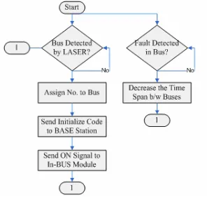
BUS Station Module
-
Available Online at www.ijpret.com
594 database. A count number is then accordingly assigned to the bus e.g., bus leaving the terminal first will be assigned a number 1. The route number of bus along with the direction information, assigned count number and license plate number is sent to the BASE Station via GSM. An example of the transmitted header is of the form “33U01LZR7240” where ‘33’ is the bus route number issued by AP Government Transportation Department, ‘U’ is upward direction of bus (‘D’ will be downward direction), ‘01’ is the count number assigned to the bus and ‘LZR7240’ is license plate number of bus. An ‘ON’ signal is also transmitted to the In-BUS Module installed in the bus for initialization. The flow chart of module software is shown in Figure 2.
In- BUS Module
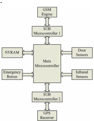
This module contains ARM cortex_M3 microcontroller interfaced with smart card based reader, GPRS enabled GSM, Touch Screen, control switches and one 8 key keypad. Microcontroller will send bus details to user module, after open the door the counting will start, in this passengers will get into bus on front side and get out from back side, on both side sensors will count the passengers entering and exiting and counting stops after the door is closed. The control switches are used for door open and close purpose. Smart card based reader used for ticketing purpose all the passengers having smart card tag will show it get their tickets registered. Generally the passengers can get monthly, weekly, one day passes passengers not have regular passes can get their ticket by giving money to conductor, conductor have the common pass for that.GSM is used for location find out, send details to user module and base station module
The smart card based reader is used for ticketing system. Once enter into bus place the Smart card place near to the Smart card reader, the reader reads the data in the card. In this reader consists of key pad also because the destination stage enter through this keypad. Once enter stage the fare amount is cut in our account prepaid card. The block diagram for this module is shown in Figure 3
BASE Station Module
-
Available Online at www.ijpret.com
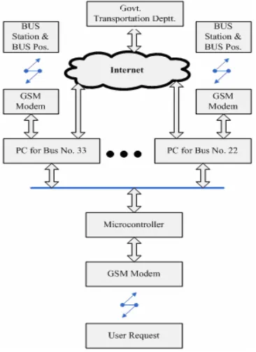
595 In first instance i.e., “33U”, ‘33’ is the route number and ‘U’ designates the direction flag while in second instance i.e., “33U10”, additional digit ‘10’ denotes the bus stop number where the passenger is standing. The microcontroller attached with this GSM modem passes on the user request to the PC dedicated for that route number. The PC after processing the request data sends desired location information in form of bus stop name to microcontroller. The microcontroller then transmits this information back to the user. The information that passenger will receive contains the location of all buses out of terminal in desired direction in former query while in case of later query, he will get the location of those buses which are coming towards the particular bus stop number in desired direction along with time information. The time information is embedded in message to account for any delay in processing the user request. An example of the information received by the user is of the form “Shivaji Chowk, Town Ship, New Campus - 11:30 P.M.” where first four strings are bus stops names telling where the buses are currently followed by the time on which the location information is get from the map and message is sent to user. BASE station also monitors the emergency situations transmitted from In-BUS Module. In addition to this, the station keeps record of security issues and traffic congestion conditions and directs the driver to change the route if desired. The block diagram of the module is shown in Figure 4.
-
Available Online at www.ijpret.com
596 Figure 2 Block Diagram if In-Bus Module
BUS Stop Module
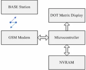
This module is installed at every bus stop to let the passenger know about the location of buses coming towards that stop. It comprises of a GSM modem, a NV-RAM and dot matrix display; all interfaced to 89C52 microcontroller .After receiving the bus location data in the form of stop names from BASE station, microcontroller stores it in nonvolatile RAM .A sample message received by BUS Stop Module installed at ‘New Campus Stop’ is of the form “33,Town Ship; 22, Apollo Hospital; 77, Public Garden; 11,Nilayam Town; 23, Gandhi Chowk; 09, Shivaji Chowk”. The message contains information of those buses only which will pass by the designated stop. First two digits of a sub-string denote the bus route number followed by the bus stop name which is the current location of bus coming towards the specified stop. Microcontroller after retrieving the stored information displays it on a 3x15 dot matrix display. The microcontroller refreshes the information with a rate of 10seconds. In case of an emergency situation, the location of next incoming bus is displayed. The block diagram of this module is shown in Figure 5.
STATISTICAL ANALYSIS AND RECOMMENDATIONS
-
Available Online at www.ijpret.com
597 to compensate the demand. BASE station transmits the statistical data along with the recommendation report to AP Government Transportation Department through internet at the end of day or as per request of transportation department.
CONCLUSIONS
In this paper, design and development of a low cost transportation management system based on integration of GPS and GSM data is described. The system comprises of various modules which are wirelessly linked with GSM modems. Cost effective SMS service of GSM network is used for the transfer of data between the modules. A new service, to facilitate the people who use public transport for traveling, is introduced inside the city. The service provides the user with current location information of desired buses based on which the user can adjust his schedule accordingly. The service therefore vanishes the need of waiting at the bus stop thus saving a lot of time. For the passengers not utilizing the service, displays are installed at bus stop to let them know the buses location coming towards that stop. The system is also efficient in handling the emergency situations e.g., in case some kind of technical fault occurred in bus, the operator at bus terminal is informed and the departure time between the buses is reduced.
-
Available Online at www.ijpret.com
598 ACKNOWLEDGMENT
Authors would like to acknowledge support from Prof. Mrs. M.D. Ingole and Prof. Mrs. M.S. Joshi for this work.
Figure 5 Block Diagram of BUS Stop Module
REFRENCES
1. Umar Farooq, Tanveer ul Haq, Senior Member IEEE, Muhammad Amar, Muhammad
UsmanAsad, Asim Iqbal.” GPS-GSM Integration for Enhancing Public Transportation Management Services “.© IEEE 2010.
2. GSM Association, „Location based service" version 3.0.0, February 2002
3. Christopher Drane, Malcolm Macnaughtan, Craig Scott „Positioning GSM telephones" -
University of Technology Sydney, April 1998
4. Snap Track, A QUALCOMM Company - Location technologies for GSM, GPRS and WCDMA
networks, September 2001
5. Available [online]: www.friendlyarm.net
6. Available [online] : www.sparrl.com
7. Available[online]: www.alldatasheet.com
8. Available [online]: www.visiontek.co.in
9. M. A. Mazidi, J. C. Mazidi, R. D. Mckinaly, The 8051
10.Microcontroller and Embedded Systems, Pearson Education, 2006.