ISSN : 2581-7175 ©IJSRED: All Rights are Reserved Page 593
Optimization of Cable Faults in TDM Optical Network
Using OTDR
D.Muthukumaran
(ECE, SCSVMV, Kanchipuram)
---************************---Abstract:
In today’s world optical fiber cable supports high band width to design a network. Now presently OAN (optical access network) used in local places to access the network. Earlier we were using OTN (optical transport network) for connecting the long distances. In our system PON (passive optical network) mechanism used to find the optical fiber break and by using OTDR (optical time domain reflectometer) technique the optical fiber fault can be analyzed. PON splits the data and voice at the customer end. Now the performance was improved using GPON (Gigabit passive optical network) which provides higher data rate. Two main terminals in the optical network i) ONT (Optical Network Terminal) ii) OLT (Optical Line Terminal) which are connected at service providers end and customer end. For detecting the failure location Centralized Failure Detection System (CFDS) is used. One of the major challenges is to maintain the network with maximum QoS in FTTH (fiber to the home) system. The proposed system has the facility for fault identification and advancements in localization of cable faults,
Keywords: Optical Fiber Cable, FTTH (fiber to the home),OTDR (optical time domain reflectometer)
---************************---I ---************************---Introduction:
Customers demanding to increase the bandwidth in the network access. Copper based cable infrastructures were limited in bandwidth. In order to increase the bandwidth optical fibers cables are introduced. It will increase the bandwidth and the number of connected users will also increase continuously. Fiber optic communication is used to transmit data, voice, video and telemetry over long distances.(i.e. interms of gigabit and beyond giga bits) And also for local area networks Fiber optic transmission system includes three major elements. They are transmitter (light source), fiber optic cable and receiver (photo detector). The transmitter
section includes the user input and optical output through optical fiber cable. It Fiber optic transmission system includes three major elements. They are transmitter (light source), fiber optic
ISSN : 2581-7175 ©IJSRED: All Rights are Reserved Page 594 cable and receiver (photo detector). The transmitter
section includes the user input and optical output through optical fiber cable.
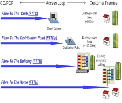
Fiber optic transmission system includes three major elements. They are transmitter (light source), fiber optic cable and receiver (photo detector). The transmitter section includes the user input and optical output through optical fiber cable. It In the past few years the network operators are going with new infrastructure FTTB and FTTH.(i.e. fiber to the building and fiber to the home). Optical fiber will be the vital thing for future broadband networks with the unlimited transmission capacity. FTTH network consists of fiber based access network with large number of end users to a central point. FTTB is known for “Fiber to the Building”. It was made by using wireless cables or twisted pair. It is also called as “Fiber to the basement”. In today’s technology optical fiber provides unlimited bandwidth and fastest high-speed data connectivity. Fiber optics uses the light to transmit data, a different architecture from that used by ADLS or VSAT. FTTB enables a wide range of uses, from web based applications, real time applications and telemedicine.
Fig 2. (Attenuation level of optical fibers)
It is extremely flexible to customer preference.
FTTX can be categorized into several types with different type of network destination. They are FTTH, FTTN, FTTC, FTTB, FTTP, etc.
II FTTH:
Optical fiber will be the main building block for the future broadband networks. The transmission capacity of the optical fiber is unlimited and it is unconditional when it is compared to existing cabling systems. The key requirements for a FTTH network are: A flexible network architecture design that can accommodate future innovations, Provision of high bandwidth services and content to each customer, to ensure maximum available capacity for future service demands, Minimize the disruption during network deployment to help fiber networks gain acceptance from network and make FTTH subscribers benefit. The access network will connect the following. They are
• Fixed wireless network antenna
ISSN : 2581-7175 ©IJSRED: All Rights are Reserved Page 595
• Subscribers in residential houses, terraces or block of flats,
• Larger buildings such as hospitals, colleges and business center.
• Key security and monitoring structures
The type of site will be a key factor in deciding the most appropriate network design and architecture. It includes Greenfield: the new build where the network will be introduced at the same time as the buildings. Brownfield: these are the existing buildings and infrastructure but it is lower standard. Overbuild: it means adding to the existing infrastructure. Various access network architecture can be implemented in FTTH. Each device at the subscriber premise is connected by a dedicated fiber to a port on the equipment in the passive optical splitter using feeder. The passive optical network consists of an optical line terminal and the optical network unit. It is usually situated at the central office or the concentration point.
Fig 3. FTTH Types
III Optical Time Domain Reflectometer (OTDR):
It is an optoelectronic instrument used to characterize the optical fiber. It injects a series of optical pulses into the fiber under test. It is one of the equivalent ways to measure the reflections caused by changes in the impedance of the cable under test. The strength of the return pulses is measured and integrated as a function of time. The reliability and quality of the OTDR based on its accuracy, measurement range, ability to resolve and measure closely spaced events, speed measurement and ability to perform satisfactorily under the various environment extreme conditions. The common types of OTDR like test equipment are Full feature OTDR, Hand held, Fiber break locator and RTU in RFTSs i.e. (Remote test unit in Remote fiber testing systems).
IV Online monitoring using OTDR:
ISSN : 2581-7175 ©IJSRED: All Rights are Reserved Page 596
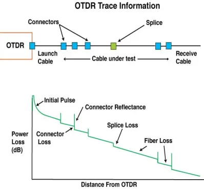
Fig 4. OTDR Trace
It is used to measure the performance of installed fiber links and to detect problems. OTDR will locate measure and detect the elements at any location. It will send the pulse to the fiber and waits for a return signal Simply by connecting one end of the fiber, it can calculate attenuation, and connector losses Its ability to measure and locate the reflectance and loss The splitting ratios 1:32 are a good compromise for bandwidth per customer and an acceptable number of customers per passive optical networks. The main contribution to the loss budget is given by the splitting devices. The higher the splitting ratio the smaller is the contribution of the individual distribution fibers and of the termination points in the measurements with an optical time domain reflectometer.The online monitoring system for fault location and optimization in FTTH network using OTDR. It can be simulated using MATLAB software.
Fig 5. Optical time domain reflectometer
The following procedure represents the online monitoring in FTTH.
• Initially start the process
• Test the optical fiber network and measured values are transferred to the systems
• Display every 8 testing results in a PC screen
• Check the line status. If it is working condition shoe the lines detail. If it is not working condition show the fault fiber and failure location.
V Results and discussion:
ISSN : 2581-7175 ©IJSRED: All Rights are Reserved Page 597
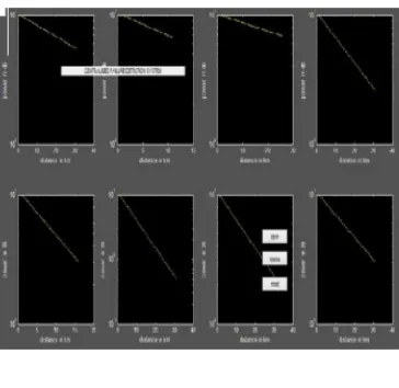
small icon box inside it shows the line fault at 1 km .it analyses the event , measurement condition and date ,time. With the above mentioned parameters it analyses the fault line and gives the information.
Fig 6a
From the figure 6a, we can say that using OTDR technique the in the n no of channels can be detected easily. The above shows the results for eight channels.
Fig 6b
From figure 4b, it is said that we can measure the amount of loss in the cable in a particular place. It is done at different places and the readings are tabulated.
References:
[1]Yonggang Wen, Vincent W.S. Chan and Lizhong Zheng, ―Efficient fault diagnosis for all-optical networks: An information theoretic approachǁ in ISIT 2006, Seattle, USA, July 9-14,2006
[2] Dan L. Philen, Ian A. White, Jane F. Kuhl, And Stephen C. Mettler, ―Single-Mode Fiber OTDR: Experiment and Theoryǁ Ieee Transactions On Microwave Theory And Techniques, Vol. Mtt-3o, No. 10, October 1982
[3] J. P. King, D. F. Smith, K. Richards, P. Timson, R. E. Epworth, And S. Wright,
―Development of a Coherent OTDR Instrumentǁ
in Journal of lightwave technology, vol. Lt-5, no. 4, April 1987
[4] Mohammad Syuhaimi Ab-Rahman, Ng Boon Chuan, Mohd. Hadi Guna Safual,Kasmiran Jumari,
―The overview of fiber fault localization technology in TDM-PON networkǁ, in 2008 International Conference on Electronic Design