Tribology in Industry
www.tribology.rsInfluence of Workpiece Hardness on Tool Wear in
Profile Micro-milling of Hardened Tool Steel
B. Sredanović
a, G. Globočki-Lakić
a, D. Kramar
b, F. Pušavec
baUniversity of Banjaluka, Faculty of Mech. Engineering, S. Stepanovića 75, 78000 Banja Luka, Bosnia&Herzegovina, bUniversity of Ljubljana, Faculty of Mechanical Engineering, Aškerčeva 6, 1000 Ljubljana, Slovenia.
Keywords: Hardness Tool wear Micro-milling
A B S T R A C T
Machining of engineering metallic materials on micro-level is very complicated. Micro-milling with solid tools, as one of microengineering technologies, is an acceptable process to machining of complex metallic micro-parts. The main problem in micro-milling is sensitivity of cutting tool, due its suppleness and short tool life, and its influences to workpiece accuracy and quality. In this paper is experimentally investigated tool wear of micro-milling tool. During machining tests, influence of workpiece hardness and process parameters is evaluated. Workpiece was cold work alloyed tool steel X155CrVMo12, hardened to different hardness 45, 54 and 63 HRc. Cutting tool was carbide ball-end micro-mill with TiAlN coating, and diameter of 0.6 mm. For different combination of input parameters, tool wear curves is presented, and signification of input parameters on tool wear is evaluated and discussed.
© 2018 Published by Faculty of Engineering Corresponding author:
Branislav Sredanović University of Banjaluka,
Faculty of Mechanical Engineering, Stepe Stepanovića 75,
78000 Banjaluka, Republic of Srpska Bosnia and Herzegovina.
E-mail: branislav.sredanovic@mf.unibl.org
1. INTRODUCTION
Nowadays, production technologies such as cutting, deforming, casting and alternative processes are employed partially in production of micro-parts and components. According to the definition, micro-machining is a production process which allows the production of parts with at least two dimensions, measured in the two perpendicular directional directions, that less than 1000 μm [1]. These production technologies are grouped together in, so called, microengineering technologies (MET). Also, in addition to this group, there are group of micro-system technologies (MST) that oriented to production of micro-electro-mechanical system
components (MEMS). Both mentioned groups are unified under micro-technologies [2]. In addition to these processing technologies, in micro-parts production process are included many others systems, such as special tool machine, special tools and fixtures, assembling systems, manipulation systems, measuring and control systems, etc. The intense development of automotive industry, aerospace industry, space industry, medicine and energy has conditioned the need for the production of parts with relatively small dimensions. Mentioned micro-parts must be functionally and constructively optimized, with high quality, accuracy, and reliability. In these systems, there is a wide range of different construction materials.
R
E
SE
A
R
A special problem in these technologies is the machining of the micro-parts with complex geometry, and made of hard-to-machining materials. These problems are encountered in machining of functional parts and mould tools and die, made of high-alloyed hardened tool
steels. In industry practice, common
technologies in machining of mentioned materials are laser beam machining (LBM) and electro-discharge machining (EDM) [3]. The main disadvantage of LBM is the impossibility of efficient three-dimensional machining due to the inability to control of beam penetration. Also, generated heat can damage the machined surface. The main disadvantage of EDM is lack of machined surface quality. EDM is very technology with very low production rate.
Acceptable solution is use of micro-milling as mechanical solid tool based technology [4]. Due to tool machine kinematics, it enables three-dimensional machining, with relatively high production rate. Main disadvantage of micro-milling is sensitivity of cutting tool, especially in milling of hardened steels. Materials of this type occupy a large percentage in the total sum of construction materials (Fig. 1).
Fig. 1. Percentages of materials in micro-milling [4].
The sensitivity of micro-milling tools is reflected through low tool life and the presence of large tool deflections. Mentioned disadvantage of micro-milling process directly influences to accuracy and quality of micro-parts. The high hardness of the workpiece material leads to intensive tool wear, and thus the increase in machining inaccuracies and machining costs.
1.1 Previous researches
The aim of this paper is to characterisation and investigation the influence of workpiece material hardness and process parameter on the tool wear. In next, are given and analysed some research by other researcher.
2. EXPERIMENTAL SETUP
Experimental research was performed at the
precision high-speed Sodick MC430L
micro-milling centre (Fig. 2). The experiments were performed in MQL lubrication condition.
Fig. 2. Experimental setup.
The SECO carbide two flute ball-end micro-mills with TiAlN coating a long neck were used. The
diameter of this mills is dc = 0.6 mm, neck length
l3 = 5 mm, helix angle of this mills ω = 20°, and
rake angle γ = 4°. The mean value of the
measured radius of cutting wedge is rc = 8 μm.
As a workpiece material, cold work alloyed tool steel X155CrVMo12 was used. In this, chrome-molybdenum based steel, percentages of alloy elements was as follow: 1.55 % of C, 0.32 % of Si, 0.35 % of Mn, 11.8 % of Cr, 0.90 % of Mo, 0.80 % of V and 0.30 % of Ni. It has excellence mechanical properties and heat conductivity,
tensile strength of Rm = 1800 - 2300 MPa, good
cross volume hardening ability, and very low machinability in cutting. In hardening, a martensitic structure with alloying elements carbides is found, that gives it exceptional hardness and wear resistance.
Table 1. Values of workpiece physical properties. Hardness
HRc
Yield strenght MPa
45 1500
54 1900
63 2200
For experimental investigation were used three
different workpiece hardness WPH = 45, 54 and
63 HRc. For mentioned hardness, frame and mean values of mechanical and structural properties, guaranteed by steel producer is given in Table 1.
Workpiece had inclination of machining surface, with angle of 20°. It is prepared by ball milling cutter, with Ø6 mm, and manually polished. As cutting parameters in experiments were: depth
of cut ap = 15 μm, cutting width ae = 16 μm, feed
per tooth fz = 10 μm/tooth, and following cutting
speeds vc = 40, 55, and 70 m/min. This
recommendations were adopted based on own preliminary and research by other researcher. Based on this, in Table 2 are shown 9 different parameters combinations of experimental runs.
Table 2. Experimental combination.
Exp no.
WPH [HRc]
vc
[m/min]
1 63 70
2 63 55
3 63 40
4 54 70
5 54 55
6 54 40
7 45 70
8 45 55
9 45 40
2.1 Measuring device and procedure
Tool wear was measured by the measuring of radius of cutting tool edge (Fig. 3). Radius of cutting tool edge is ability parameter which defining of tool edge geometry variation in machining time due the tool wear.
Measuring of tool wear, over cutting edge radius were carried out on optical scanner ALICONA InfiniteFocus SL (Fig. 4). Scanning is performed by continuously vertically optical lens moving, and automatically taking of successive array of sample surface images, by so called variation of the focus technique [19].
Fig. 4. AliconaInfiniteFocus SL device.
Mentioned technique can be interpreted by schema on Fig. 5. From the currently obtained image, only the sharpest parts are distinguished, their colour is captured, and noted the current position of the lens. After analysing the images, the information obtained is integrated into the topographic view of the scanned surface.
Fig. 5. Focus variation onInfiniteFocus SL [19].
On Fig. 6 is shown the user interface of Alicona software. This interface allows measuring of
cross section of topographic scan of cutting tool tip. Based on the selected area, the cutting edge contour can be obtained and measured.
Fig. 6. Alicona measuring software.
3. RESULTS AND DISCUSSIONS
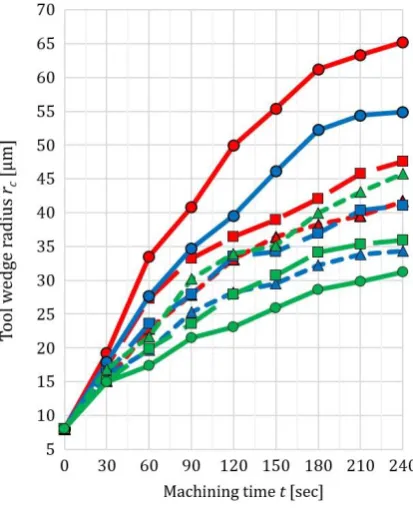
Increase of cutting edge radius is measured for different input parameter combination. This procedure was included milling of workpiece, stopping of machine and very quickly scanning of micro-mill tip. Run stopping is performed for each 30 seconds. On Fig. 7 is shown cutting tool edge radius increasing during machining.
Fig. 8. Image and scan of new tool.
Image and scan of new cutting tool are shown on Fig. 8. On scan can be noticed tool tip and cutting edge geometry, and traces of tool brushing during its manufacturing. Measuring of tool wear was stopped after 240 seconds. Based on curve shapes on diagraph from Fig. 7, can be concluded that tool wear but cutting edge radius in fact, progressive and nonlinear, increases during machining time. Can be concluded that combinations with higher workpiece hardness and cutting speed give intensive tool wear. On end of measuring runs, cutting edge radius had maximum value of 65 μm for hardness of 63 HRc and cutting speed of 70 m/min. Minimum value can be noticed in experimental combination 45 HRc and 40 m/min, and its values is 32 μm.
Fig. 9. Image and scan of tool in experimental run 8.
On Figs. 9 and 10 are shown scans of cutting edge on end of measuring run. Based on it can be concluded cutting edge destruction.
Fig. 10. Image and scan of tool in experimental run 1.
In both cases can be noticed intensive destruction of coating layer on cutting edges. This destruction is caused by intensive abrasive wear that effected by very hard carbides particle in workpiece material structure. Built-on-edge on cutting tool (BUE) is noted at higher tool wear stages. BUE was higher at higher workpiece material hardness. Also, can be concluded some of BUE significantly changing cutting edge geometry. In first, built-on-edge decreases the rake angle of tool wedge. Base on measuring, it is concluded that maximum tool wear or cutting edge radius is greatest on touching point between tool and workpiece, where chip cross section area is maximum. Furthermore, it decreases with chip cross section area decreasing, in the direction of a greater equivalent cutting tool radius. In this direction, there is increasing of effective cutting speed in some percentage, but it do not has influence on tool wear.
Definition of tool life for micro ball-end mills, as economical criterion of machinability, is not precisely defining and standardized in literature. Some authors are defined it over criterion of tool diameter decreasing of in flat-end mill machining. Also, some researcher is evaluated the flank wear on clearance surface on cutting tool wedge, as criterion of tool life. However, in research that presented in this paper, tool life criterion is defined as machining time when cutting edge radius reaches value of 30 μm. Increasing the cutting edge radius causes phenomenon of the size effect. The size effect is caused by same value rang between cutting
parameters, cutting tool geometrical
parameters, and mechanical and structural properties of workpiece material [1-4]. Presence of size effect can be noticed in machining with low values of cutting depth and feed per tooth, and also in later stages of cutting tool wear. In this cases, there are mechanism of material plugging during chip forming, mechanism of machined surface brushing, sudden rise of cutting tool deflection, and etc. (Fig. 11).
Table 3. Calculated economical and productivity parameters of micro-milling.
Exp no.
T
[min]
MRR
[mm3/min]
MRV
[mm3]
1 0.88 0.186 0.164
2 1.23 0.146 0.180
3 1.75 0.106 0.186
4 1.17 0.186 0.217
5 1.78 0.146 0.260
6 2.63 0.106 0.280
7 1.48 0.186 0.276
8 2.37 0.146 0.345
9 3.58 0.106 0.380
For this criterion is evaluated tool life T [min], which values for different input parameters are given in Table 3. Graphically, dependence of tool life on workpiece hardness and cutting speed is shown on Fig. 12.
Fig. 12. Comparison of tool life for different inputs.
Maximum tool life, with values of T = 3.58 min, is
obtained in experimental combination of hardness 45 HRc and cutting speed of 40 m/min. According previous conclusions, minimum tool
life, with values of T = 0.88 min, is obtained for
hardness of 63 HRc and speed of 70 m/min. Based on cutting parameters, area of chip cross section and length of machining, there is
calculated material removal rate MRR
[mm3/min], as productivity criterion. As product
of MRR and T, there is calculated material
removed volume MRV [mm3]. Comparison of
tool life versus material removed value is shown on Fig. 13.
Fig. 13. Tool life and material removed volume.
Differences of MRV for machining with same workpiece hardness and different cutting speeds are not great. In other hand, machining with different workpiece harnesses and cutting speed
shows low differences of MRV. This observations
lead to conclusion that workpiece with higher hardness must be machined on lower cutting speeds.
Modelling of tool life was based on ANOVA,
which performed in software DesignExpert®.
According to it, mathematical model is presented as formula (1):
14.92 0.19 1.17 c 0.002 c
T WPH v WPH v . (1)
Signification of input parameters and model of tool life is presented in Table 4.
Table 4. Results of ANOVA
Sum of
squares square Mean F value
p value
Model 5.77319 1.9244 294.87 < 0.0001
A-HRc 2.12415 2.1241 325.48 < 0.0001
B-vc 3.27082 3.2708 501.18 < 0.0001
AB 0.37823 0.3782 57.95 0.0006
Residual 0.03263 0.0063
Fig. 14. Modelled values of tool life.
Fig. 15. Measured versus predicted values of tool life.
On Fig. 14 is shown graph of influences of workpieces hardness and cutting speed on tool life, obtained on mentioned mathematical model. Also, on same graph are shown measured values. Based on it, can be concluded high matching of measured and predicted values of tool life. It is also noted on graph that shown on Fig. 15. Based on ANOVA, there are concluded the predicted values standard deviation of 0.081. Also, predicted R-squared value is 0.975 and mean error is 1.87 %.
4. CONCLUSIONS
In this paper, of influence of workpiece hardness and cutting speed on tool wear in ball-end micro-milling of tool steel, in MQL lubrication condition, is investigated. Tool wear is evaluated by increasing of cutting edge radius, which measured by fast focus variation scanner. Based on literature sources, mentioned cutting edge radius is very significant factor. Increase of mentioned radius causes phenomena of size effect and related negative phenomena which is not found in machining on macro level [20].
According of experimental results, there was evaluated economical criterion – the tool life of ball-mills, and productivity parameters of
machining, such is MRR and MRV. Main
mechanism of tool wear was abrasive wear which destroyed tool coating layer very fast. Also, there noted adhesive wear mechanism, which caused BUE and changed cutting wedge geometry. In paper is concluded that higher workpiece hardness and higher cutting speed causes intensive tool wear and low tool life. Can be concluded that workpieces with hardness, traditionally, must be machined on low cutting speeds. However, tool life has low value in any
case. Maximum tool life, T = 3.58 min, is milling
of workpiece with hardness of 45 HRc, on cutting speed 40 m/min. Based on measured
and calculated values, modelling was
performed, based on ANOVA. Modelling process is resulted with very accurate model, with R-squared value of 0.975.
Results of research in this paper are part of extensive research on profile micro-milling of hardened tool steel. As future research, influence of other cutting parameters and machining condition will be performed. Based on this researches, optimisation will be used with aim get appropriate cutting parameters. This will lead to higher productivity and economy, and quality and accuracy of micro-parts, in micro-milling of tool steels and difficult-to-machine materials.
Acknowledgement
This paper is results of activities on interstate bilateral project, in cooperation between Department for management of production technologies at FME Ljubljana and Laboratory of cutting technology and machining systems on Department for production and computer aided technologies at FME Banja Luka.
REFERENCES
[1] L. Alting, F. Kimura, H.N. Hansen, G. Bissacco, Micro-engineering, CIRP Annals - Manufacturing Technology, vol. 52, iss. 2, pp. 483-695, 2003,
doi: 10.1016/S0007-8506(07)60208-X
International Conference on Precision Engineering, 18-20 July, 2001, ICPE 2001, Yokohama, Japan, pp. 3-12, doi:
10.1007/0-306-47000-4_1
[3] Y. Qin, A. Brockett, Y. Ma, A. Razali, J. Zhao, C. Harrison, W. Pan, X. Dai, D. Loziak, Micro-manufacturing: research, technology outcomes and development issues, The International Journal of Advanced Manufacturing Technology, vol. 47, iss. 9-12, pp. 821-837, 2010, doi:
10.1007/s00170-009-2411-2
[4] M.A. Camara, J.C. Rubio, A.M. Abrao, J.P. Davim, State of the art on micromilling of materials - a review, Journal of Materials Science Technology, vol. 28, iss. 8, pp. 673-685, 2012, doi:
10.1016/S1005-0302(12)60115-7
[5] I. Tansel, O. Rodriguez, M. Trujillo, E. Paz, W. Li, Micro-end-milling, I. Wear and breakage, International Journal of Machine Tools and Manufacture, vol. 38, iss. 12, pp. 1419-1436, 1998,
doi: 10.1016/S0890-6955(98)00015-7
[6] G. Bissacco, H.N. Hansen, L. DeChiffre, Micromilling of hardened tool steel for mould making applications, Journal of Materials Processing Technology, vol. 167, iss. 2-3, pp. 201-207, 2005,
doi: 10.1016/j.jmatprotec.2005.05.029
[7] G. Bissacco, H.N. Hansen, L. DeChiffre, Size effects on surface generation in micro milling of hardened tool steel, CIRP Annals, vol. 55, iss. 1, pp. 593-496, 2006,
doi: 10.1016/S0007-8506(07)60490-9
[8] A. Aramcharoen, P.T. Mativenga, S. Yang, K.E. Cooke, D.G. Teer, Evaluation and selection of hard coatings for micro milling of hardened tool steel, International Journal of Machine Tools and Manufacture, vol. 48, iss. 14, pp. 1578-1584, 2008,
doi: 10.1016/j.ijmachtools.2008.05.011
[9] A. Aramcharoen, P.T. Mativenga, Size effect and tool geometry in micromilling of tool steel, Precision Engineering, vol. 33, iss. 4, pp 402-407, 2009, doi:
10.1016/j.precisioneng.2008.11.002
[10] F. Klocke, F. Quito, K. Arntz, A. Souza, A study of the influence of cutting parameters on micro milling of steel with CBN tools, in Micromachining and Microfabrication Process Technology XIV, 24-29, January 2009, SPIE 7204, San Jose, United States, Society of Photo-Optical Instrumentation Engineers, pp. 1-10.
doi: 10.1117/12.808554
[11] S. DeCristofaro, G.C. Feriti, N. Funaro, A. Santandrea, M. Lucassino, C. Stefanini, A. Merlo, P. Dario, A study of cutting parameters influence on micromilling of hardened steels, in 8th International Conference on Multi-Material
Micro Manufacture, 8-10 November 2011, 4M 2011, Stuttgart, Germany, pp. 277-280, doi: 10.3850/978-981-07-0319-6_206
[12] A. Gilbin, M. Fontaine, G. Michel, S. Thibaud, P. Picard, Capability of tungsten carbide micro mills to machine hardened tool steel, International Journal of Precision Engineering and Manufacturing, vol. 14, iss. 1, pp. 23-28, 2013,
doi: 10.1007/s12541-013-0004-3
[13] E. Krebsa, P. Kersting, Improving the cutting conditions in the five axis micromilling of hardened high speed steel by applying a suitable tool inclination, Procedia CIRP, vol. 14, pp. 366- 370, 2014, doi: 10.1016/j.procir.2014.03.032
[14] B. Escolle, M. Fontaine, A. Gilbin, S. Thibaud, P. Picart, Experimental investigation in micro ball end milling of hardened steel, Journal of Materials Science and Engineering, vol. 5, no. 9-10, pp 327-338, 2015, doi: 10.17265/2161-6213/2015.9-10.001
[15] S.N.B. Oliaei, Y. Karpat, Influence of tool wear on machining forces and tool deflections during micromilling, International Journal of Advanced Manufacturing Technology, vol. 84, iss. 9-12, pp. 1963-1980, 2016,
https://doi.org/10.1007/s00170-015-7744-4
[16] K.M. Li, S.Y. Chou, Experimental evaluation of minimum quantity lubrication in near micro-milling, Journal of Materials Processing Technology, vol. 210, iss. 15, pp. 2163-2170, 2010,
doi: 10.1016/j.jmatprotec.2010.07.031
[17] J.B. Saedon, S.L. Soo, D.K. Aspinwall, A. Barnacle, N.H.Saad, Prediction and optimization of tool life in micromilling AISI D2 (62 HRc) hardened steel, Procedia Engineering, vol. 41, pp. 1674-1683, 2012,
doi: 10.1016/j.proeng.2012.07.367
[18] E. Kuram, B. Ozcelik, Micromilling performance of AISI 304 stainless steel using Taguchi method and fuzzy logic modelling, Journal of Intelligent Manufacturing, vol. 27, iss. 4, pp. 817-830, 2016,
doi: 10.1007/s10845-014-0916-5
[19] R. Danzl, F. Helmli, S. Scherer, Focus Variation – a Robust Technology for High Resolution Optical 3D Surface Metrology, Strojniški vestnik - Journal of Mechanical Engineering vol. 57, iss. 3, pp. 245-256, 2011, doi:
10.5545/sv-jme.2010.175
[20] C.H. Lauro, L.C. Brandão, S.L.M. Ribeiro Filho, D. Baldo, Analysis of the forces in micromilling of hardened AISI H13 steel with different grain sizes using the Taguchi methodology, Advances in Mechanical Engineering, vol. 6, 2014, pp. 1-10,
![Fig. 1. Percentages of materials in micro-milling [4].](https://thumb-us.123doks.com/thumbv2/123dok_us/9802916.1966262/2.595.77.266.433.530/fig-percentages-materials-micro-milling.webp)