Published online November 12, 2014 (http://www.sciencepublishinggroup.com/j/ijiis) doi: 10.11648/j.ijiis.s.2014030601.30
ISSN: 2328-7675 (Print); ISSN: 2328-7683 (Online)
The magnetic induction communications for the wireless
underground sensor networks
Farzam Saeednia
1, *, Shapour Khorshidi
2, Mohssen Masoumi
31
Department Of Electrical Engineering, Kazerun Branch, Islamic Azad University, Kazerun, Iran
2
Air-Sea Science and Technology Academic Complex, Shiraz, Iran
3
Department Of Electrical Engineering, Jahrom Branch, Islamic Azad University, Jahrom, Iran
Email address:
[email protected] (F. Saeednia),[email protected](S. Khorshidi), [email protected] (M. Masoumi)
To cite this article:
Farzam Saeednia, Shapour Khorshidi, Mohssen Masoumi. The Magnetic Induction Communications for the Wireless Underground Sensor Networks. International Journal of Intelligent Information Systems. Special Issue: Research and Practices in Information Systems and Technologies in Developing Countries. Vol. 3, No. 6-1, 2014, pp. 109-114. doi: 10.11648/j.ijiis.s.2014030601.30
Abstract:
The most important difference between the wireless underground sensor networks (WUSNs) andthe wireless ground sensor networksis the propagation environment of the signal .In fact, the underground environments consist of soil, rock and water instead of the air. The challenging reasons of these environments to propagate the wireless signal via the Electro Magnetic (EM) 2waves are considered as: the high path loss, channel dynamic conditions and the high size of antenna. At the present study, the details of Bit Error Rate (BER) 3 for 2PSK modulation, path loss and the bandwidth of the Magnetic Induction (MI) 4Systems and Electro Magnetic (EM) Waveguide in the underground environment areevaluated. Meanwhile, a new method isintroduced via MI waveguide that provided the constant conditions of channel by the small inductive coils. At the end of this study,itisfounded that the transmission range in MI waveguide system would be raised and the path loss in that system would be declined severely.Keywords:
Channel Modulation, MI Waveguide Method, Underground Communications, Wireless Sensor Networks, Magnetic Induction1. Introduction
The Wireless Underground Sensor Networks (WUSNs) have the wireless sensors that are buried underground. WUSNs have so many applications such as the coverage, easy to use, appropriate data, reliability and the cover density. The other applications are the control of the soil conditions, earthquake, landslides forecast, the underground substructures control, the landscapes management and security [1, 2].
It can be mentionedthat the underground propagation environment consists of soil, rock and water instead of the air that confront us with three challenges if it is applied for the wireless communications via the Electro-Magnetic (EM) Waves: The high path loss, channel dynamic conditions, and Antenna size [3].
Akyilidizet.al,[2]evaluated the wireless communications networks installed in the underground and also the propagation via electromagneticwaves. Meanwhile,years later, Zhi Sun and Akyilidiz [9] compared the traditional methods and MI systems of the wireless underground
communications.At the end of this study, the wireless underground communications were evaluated by a new method called “MI Waveguide” [9].
In the second part, the theoretical structure of a new methodcalled MI Waveguide was presented that used some inductive coil.The third section of simulation considered the theory of second section and the comparison of communication methods.
2. The MI Waveguide Characteristics
waveguide are conducted by some small wire cores called as Induction coils (there is no multipath disappearance in MI waveguide) due to the low resistance of the irradiation in the coil inductance [2, 5, 6].
For MI Waveguide Method,some multiple factors were applied such as the soil properties, soil size, number of rotations in each ring of coil, coil resistance in the operational frequency [6].Our analyses indicate that MI Typical Systems has a higher transmission range and lesser bandwidth than EM waveguides systems. But neither MI typical system nor EM waveguide system is able to provide enough communication range for the practical applications of WUSN.
3. The MI Waveguide for the
Underground Communications
The propagation characteristics of Electro Magnetic (EM) waves in the underground environment (soil, water, rock) were presented in fig.3. The analyses indicate that the path loss is much higher than the ground cases and its reason is the absorption in the elements of the underground environment. The success in the communications dependson the combination of operational frequency and soil. Thus, as the operational frequency decreases, the path loss is decreased too but we need a larger antenna [3]. One suggested solution is to apply some antenna with 0.3m length to receive 300 MHz signals. Meanwhile, the signal transmission rangeof these antennas is about 4 meter. Recently, the Magnetic Induction method has been used as a new physical layer method for the wireless communications but it has disadvantages as the high path loss and Low bandwidth.MI can be considered as an alternative communication method in Bluetooth. For the first time, MI was introduced in wireless underground communications. According to the previous studies, MI transmission isn’t influenced by the soil type, combinations, concentration or the moisture [7].
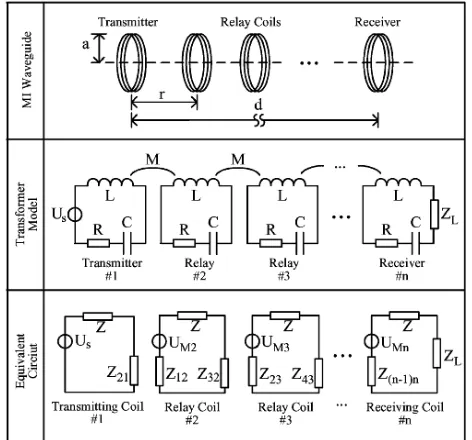
Fig. 1. Communication Channels Model for MI Waveguide.
Although the channel is constant and the transmission range of the MI typical system is more than EM, its transmission range is still short for the operational applications. One suggested solution is to apply several simple relay inductioncoilswithout any energetic resourceandprocessing machine between the receiver and transmitter to conduct MI waves by EM Waves method. The procedure is that at first, the sinusoidal current in the transmitter’scoil loop induces a sinusoidal current in the primary relay induction coil point .Then this sinusoidal current in the coil loop of the primary relay induces another sinusoidal current in the secondary loop and this procedure continues until to reach the receiver. As it is shown in the first row in fig.1, a typical structure of n-2 coil loops has been placed between the axis of receiver and transmitter. Thus, n,the total number of coil loop;r,the distance between the adjacentcoil loops/ringsand d is the distance between the receiver and transmitter. D=(n-1)r ; a is the radius of coil loops. According to the second row in fig.1, it can be said that each relay coil consists of the receiver and transmitter’s coil loop that is loaded via a capacitor, C. In order to transmit the magnetic signals, an appropriate design should be presented for the capacitor value and the effective value of the resonant coil loop to create the mutual induction among each pair of coil loop that depends on the proximity of the loops. In the underground communications, we considered the distance between two relay loops as 5meters. But that distance was higher than the maximum of the communication range in EM waves system. Despite this, the application of relay loop instead of the underground devices in MI system reduces the costs. In the next part, an appropriate distance is obtained by analyzing the distance of MI waveguide relay loop. The distance of loops in comparison with the relay loop 0.15m is high enough and it causes that the coils only have a mutual self-induction with their neighbors.
3.1. System Modeling
For modeling the MI waveguide, all loops must have the same parameters (resistance, mutual inductance and self-inductance). M is the mutual inductance between the adjacent coils, Ua is the voltage of transmitter battery, L, the
self-inductance of the coils, R is the coil resistance, C is the loaded capacitors in each coil and ZL is the impedance of the
load in the receiver .The equivalent circuit of the multistep transformer shown in the third row in fig.1 is as follow:
Z = R + jωL +jωC1
Z =Z + Zω M i = 2,3, … , n − 1 and Z = Z
Z =Z + Zω M i = 3,4, … . n and Z =ω MZ #
whereas Z i − 1 is the effect of ith coil on i − 1 ./loop andvice versa. Then the received power in receiver is calculated as:
P1= Re 3 +4 .&'5
,
+5)* 5 + +4,6 (2)
3.2. System Optimization
If the coil loops are resonated, UMnvalue as the induced
voltage in the receiver will be reached to its maximum value that makes the received power to reach to its maximum on the basis of equ.1.Therefore, we should design a capacitor to prevent from reducing the actual value of received power severely because of self-induction in the coil loops (jwL + 89: ; = 0
By the self-induction in equ.7, the capacitor value is calculated as:
C ==,>,?@A (3)
When the coil loops are resonated,the received power, UMn
can be extended as:
U% = U-∗ −jωMR ∗ − jωM
R +=,C%,∗ −
jωM R + =,%,
C D,',E
… … ..
= U-∗ j ∗F*∗F,∗ … … . .F5)* (4)
According to the above-mentioned equations, it can be said that the multiplying operation, x , x , xH, … , x is n-1 degree from x = R/ωMwritten asξ 8:%C ; , n − 1 , the following equation is :
ζ 8=%C , n − 1; = b 8=%C ; + b 8=%C ; + ⋯ +
b 8=%C; + b 8=%C ; + bM (5)
Whereas, Nb , i = 1,2, … , n − 1O are the polynomial coefficients that aren’t influenced by the parameter for an special and constant n. Since the coil loop has been resonant, it causes that the load impedance is matched with the pure strength. So, the load impedance is regarded asZ =
Z + R
PPPPPPPPPPPPPPP. Finally,in MI waveguide if the receiver is d meter away from the transmitter and there is some loops with n-2 relay coil between them,the received power will be written as:
P1 d =Q +5)* 5 C .S,8E&R,
D' , ; (6)
Whereas, d is the transmission range, d= (n-1) r. Like MI typical system, the transmitted and received powers in MI system are reduced simultaneously as the transmission distanceincreased. Thus, MI waveguide loss, LMIG is defined
as:
L%TU d = −10 logPP1 d . rM
≅ 10 log [4 Z R + R + 20logζ \ωM , n − 1]^R
= 10 log 4
_ ` ` ` ` a
1 + 1
8=%C ; + *
8 ED';,b **b⋯..cd
d d d e
+20 log fb 8=%C ; + ⋯ + b 8=%C ; + bMg (7)
Whereas, Pt(rD) isdefinedas the transmission power when
the transmitter is very close to the receiver and there is no induction coil.On the basis of equ.7, the path loss in MI waveguide system is a function from R/ωM .
Meanwhile, ξ :%C , n − 1 is a polynomials that has a significant effect on the path loss. Thus, the path loss is a monotonic function with the increased performance from R/ωM. Thus, in order to reduce the path loss, R/ωM must be reduced to the minimum value. By the wire resistance, R and the mutual inductance, M in equ.4 and equ.6 [4],R/ωM is expressed as [9]:
C
=%=
QCh
=>?@ . 8 1 A;
H
(8)
Note that, the relay distance, r is 1/ (n-1) of the total transmission range, d.
By this method, the effect of Cubic functionfor the path loss can be decreased. With regard to this scheme, it is possible to decrease the path loss by considering the following items:
- The decrease of relay distance to the coil radius, r/a. -The increase of operational frequency, ω and the number of loops in the coil, N.
- The decrease of wire resistance, RD
-But there are some other factors to minimize the path loss (the relay distance to radius). In order to facilitate the deployment of coils, it is expected to have a decrease in the total transmission range. In this section, in order to keep the advantages of the above case on the underground EM waveguide system, the relay distance is restricted to the minimum value, 4 m to have the maximum release in the transmission range. With regard to the coil radius, 0.15 meters, the relay distance to coil radius is very high.
-There are other factors included in to this law and there isn’t possibleto increase the operational frequency and the number of rotations in the coil loop. Thus, these two parameters can be restricted by equ.3. The capacitors with loads in each resonant coil should be more than 10PF.
maximize N and ω. Furthermore, very high operational frequency and the high number of coil rotations causes the severe operation arising from Parasitic Capacity[22].In this section, the operational frequency is 10 MHz,the number of rotations is 5 for each coil and the capacitor value is 35PF.
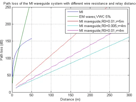
Fig. 2. the comparison of the path loss in MI waveguide with EM,MI wave systems.
Although the decrease of coil resistance can reduces the path loss, two problems may occur: 1) in order to decrease the coil resistance, the wire diameter must be raised. It causes the costs increase and the loop becomesheavier. 2) The decrease of coil resistance causes some fluctuations in the received signal that make problems in receiving the signal in the receiver. In this study, the coil was made of copper with 0.45mm diameter. With regard to the AWG standard[8], the resistance of unit length, RDis 0.01ji
.
3.3. Numerical Analysis
3.3.1. Path Loss
The path loss in the MI waveguide system in Equ.7 were evaluated viaMATLAB software. The results were shown in fig.2. In order to have a better comparison, the path loss of EM waves system with the operational frequency, 300MH in the soil with VWC, 0.5 and the path loss of typical MI system with the operational frequency, 10MHz were drawn. According to the mentioned discussions in the fourth section, MI system operation can’t influence on the soil properties. The soil environment has the permeability as the air (4k ∗ 10 lm/n). So in evaluating MI waveguide, there is no need
to consider the environmental parameters. Except the evaluation of the effects of special parameters , all available loops in the transmitter , receiver and relay points have some default values: radius, a=0.15m and the number of rotationsin system , N=5.The resistance of unit length for the natural coil and the low resistance coils are R0=0.01Ω/m and R0=0.005Ω/m respectively. The operational frequency is set on 10MHz. The relay distance, r is also 5m.The total number of coil loops, n is determined by the transmission distance, where d= (n-1)r. The path loss of MI waveguide system, dB with the different transmission distances, d, the different
relay distance, r and different coil resistance, RD have been
shown in fig.2. It can be found that MI waveguide system has a lower path loss in 100 dB and even with the transmission distance, 250m to EM magnetic and MI typical systems. But its path loss increases in more than 100 dB with the distance, 5 m. Furthermore, the path loss can be obtained via decreasing the relay distances and the coil resistance.
3.3.2. Bit Error Rate
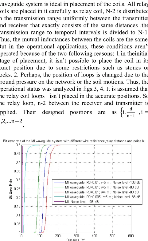
The BER and MI waveguide characteristics were evaluated in fig.7. The analyses of third section with 2PSK modulation were shown as the Scheme Modulation .Two noise levels were considered which the noise moderatelevel, Pn was regarded in low parasite scenario, -103dBmwhile in
high noise scenario, Pn is -83 dBm. The transmission power
value,Pt is also set on 10 dBm. In fig.7, BER in MI
waveguide system has been shown as a function of transmission distance, d with the different relay distances, r and different wire resistance, RD.In fact, EM waveguide
system and MI typical system has been drawn for comparison. by comparing the low transmission range of two other methods ( lower than 10m) , it can be said that even in high parasite scenarios , the transmission range of wave is about 250m.. It means that in comparison with two other systems, the transmission range in MI waveguide system will be raised for more than 25 times.In compliance with the analyses in the path loss, the transmission range of MI waveguide can be increased by decreasing the relay distance and resistance of the coil.
3.3.3. Bandwidth
Assuming that there is only one frequency in the transmission signals, thepath loss in high levels and in the transmission range of MI waveguide system is calculated. According to this central frequency, all coils can be resonated.But if there is any kind of deployment from the central frequency, the resonance status of each coil will be disappeared. So, it is necessary to analyze the band width in MI waveguide system. In fig.2, the frequency response of MI waveguide system was shown with different relay distances, r and different wire resistance, RD. The number of relay
coilwas shown by constant 7.The results indicate that when the operational frequency is 10MHz, the band width 3dB in MI waveguide system will be placed in a same range as MI typical system that is about 1 kHz to 2 kHz. Although the lower coil resistance can decrease the path loss in the central frequency, thefluctuations of the frequency response is such a serious problem that may make some problems in the transferring the power to the receiver. The band width can be increased as the relay distance reduces. But for a special transmission range, it can be said that the reduction of relay distance means that we need more relay loops. Two possible operational parameters are as follow:
1. The relay distance , r=5m and the resistance of unit length, RD,RD=0.01Ω/m that make the system
conductor in operation in 10KHz frequency ,the radius, 250m and the band width,1KHz.
length, RD,RD=0.01Ω/m that make the system
conductor in operation in 10KHz frequency,the radius, 400m and the band width,2 KHz.
3.3.4. The Deployment Effect
It must be mentioned that the high operation of MI waveguide system is ideal in placement of the coils. All relay coils are placed in it carefully as relay coil, N-2 is distributed in the transmission range uniformly between the transmitter and receiver that exactly consists of the same distances .the transmission range to temporal intervals is divided to N-1. Thus, the mutual inductances between the coils are the same. But in the operational applications, these conditions aren’t operated because of the two following reasons: 1.in theinitial stage of placement, it isn’t possible to place the coil in its exact position due to some restrictions such as stones or rocks. 2. Perhaps, the position of loops is changed due to the ground pressure on the network or the soil motions. Thus, the operational status was analyzed in figs.3, 4. It is assumed that the relay coil loops isn’t placed in the accurate positions. So, the relay loop, n-2 between the receiver and transmitter is applied. Their designed positions are as oi. p , i =
1,2,…n−2.
Fig. 3. The Comparison of Bit Error Rate of MI Waveguide with Different Relay Distances and Noises for EM and MI waves system.
Fig. 4. The Frequency Response of MI Waveguide System with Different Wire and Remote Relay Resistances.
Xjin the relay loop, i is a Gaussian random variable with
the mean, i.d/(n-1) and the standard deviation , σr. After that,
it can be said that the transmission distance, d is dividable to
n-1 intervals with r1,r2,rn-1 whereas r = x − x are the
transmitter and receiver positions respectively. Itwas assumed that the standard deviation had been designed for the relay distances 5%,10% or 20%. The other simulation parameters were set on the default values. The results were obtained from 100 samples in average. Both the moderate value and the standard deviation were drawn in the figure. It can be said that operationally, there is also an additional path loss. Furthermore, when the standard deviation is 20% , the band width decreases severely.The level of additional path loss and the reduction of band width are determined by the standard deviation. The higher standard deviation makes more problems in the system. Furthermore, as the transmission distance increases, the additional path loss will be raised too. When the deployment increases, the standard deviation of the path loss and the band width are also raised severely.This indicates that as the deployment occurs, the reliability of MI waves system is also reduced. Meanwhile, as the standard deviation is lesser than 10%, we can ignore the effect of deployment on the operation of MI waves system.
4. Discussion and Conclusion
In the underground wireless communications, the traditional methods via EM waves have three major challenges: the high path loss because of the material absorption, the channel dynamic conditions because of the various properties of the soil and the very high size of the antenna.
MI is an alternative method with the same channel conditionsand it can accomplish the communications with the small cores .At the present study, one analytic model was shown that indicated the communicational underground channel characteristics of MI. According to the channel analysis, we presented one MI wave method that increased the transmission range. Our analysis indicated the following results:
transmission power decreases simultaneously with regard to the received power.This is ideal for WUSNS restricted energy. MI Waves Method decreases the path loss effectively. It must be mentioned that the cores of relay coil don’t consume energy. hence, their costs are very low. The band width of MI system is similar to one MI typical system. In comparison with MI typical system and EM waves, the transmission range of MI waves increases severely.
References
[1] I. F. Akyildiz, W. Su, Y. Sankarasubramaniam, and E. Cayirci, “Wireless sensor networks: A survey,” Computer Networks., vol. 38, no. 4, pp. 393–422, March 2002.
[2] I. F. Akyildiz and E. P. Stuntebeck, “Wireless underground sensor networks: Research challenges,” Ad Hoc Networks (Elsevier),vol. 4, pp. 669–686, Jul. 2006.
[3] L. Li, M. C. Vuran, and I. F. Akyildiz, “Characteristics of underground channel for wireless underground sensor networks,” presented at the Med-Hoc-Net’07, Corfu, Greece, Jun. 2007.
[4] T. A. Milligan, Modern Antenna Design, 2nd ed. Piscataway, NJ: IEEE Press, 2005.
[5] N. Jack and K. Shenai, “Magnetic induction IC for wireless communication in RF-impenetrable media,” presented at the IEEE Workshop on Microelectronics and Electron Devices (WMED 2007), Apr. 2007.
[6] J. J. Sojdehei, P. N. Wrathall, and D. F. Dinn, “Magneto-inductive (MI) communications,” presented at the MTS/IEEE Conf. and Exhibition (OCEANS 2001), Nov. 2001.
[7] A. R. Silva and M. C. Vuran, “Development of a testbed for wirelessunderground sensor networks,” EURASIP J.WirelessCommun.Netw.(JWCN)[Online].Available:http://cs e.unl.edu/~mcvuran/ugTestbed.pdf
[8] Standard Specification for Standard Nominal Diameters and Cross- Sectional Areas of AWG Sizes of Solid Round Wires Used as Electrical Conductors, ASTM Standard B 258-02, ASTM International, 2002.