Innovative Security Technology for Optical Fiber Data Transmission
Using Optical Vortex
Marek Życzkowski
*, Konrad Dominik Brewczyński, Mateusz Karol
Institute of Optoelectronics, Military University of Technology, Warsaw, Poland .
Received 10 July 2017; received in revised form 11 August 2017; accepted 13 August 2017
Abstract
This article presents system concept of the use of an optical vortex phenomenon for secure data exchange in
the optical fiber line. Optical vortices are obtained in free space, and then they are introduced into the optical fiber.
Their p roperties are e xa mined in the world [1-2], so far, wh ich directly shows the ability to increase the bandwidth
of optical fiber. Given the structure and characteristics of the optical vorte x, the authors propose to set a secure
optical link. Such link can be provided in two ways .
The first method involves coding an information on optical vorte x. The data in the optical fiber line can be
coded by time-position modeling of the optical properties of the vortex. In addition, changing the topology of the
optical vortex and the use of mode dependencies also offer the possibility of information coding.
The second way to use the vortex in the optical fiber is setting of optical fiber sensor, sensitive to the
disturbance of fiber-optic trans mission line. It can be achieved by propagation both - coded informat ion in basic
mode and an optical vorte x in a mic rostructural fiber. In the case of physical impact on optical fiber the vorte x
disturbs the flow of data, forming the information noise on the output of the fiber.
The artic le p resents the setup of the generation of optical vorte x, for the te leco mmunications bandwidth,
developed at the Institute of Optoelectronics, in the Security Systems Group and initial tests of the setup .
Keywor ds: optical vortex, fiber optic, safe communication
1.
Introduction
The work on obtaining and using optical vortices in teleco mmun ications fiber optic networks, undertaken at the
Institute of Optoelectronics, is the result of global de mand for increasing the speed of informat ion flow and for increasing the
security of data transmission. Each day the internet traffic increases. According to MINTS the interpolated growth of
demand for data is linear since about 2007 and is projected to rema in so [3]. According to R.J. Essiambre and R.W. Tkach
we are inevitably approaching the limit of the capacity of optical fibers. The only solution is to search for new methods of
data encoding and new possibilit ies of denser packing data. The solution may be optical vortices, which can propagate in
telecommun ications optical fiber parallel to data coded current technical solutions. Space Division Multiple xing allows
increasing the capacity of an optical fiber.
There must be maintained appropriate conditions for the propagation of optical vortices. First of all optical vort ices
propagate only multi-core optica l fibers [4]. Another proble m with working with optical vortices is their instability over long
distances. Currently the world record to maintain a stable optical vortex is its propagation on distance 1.1 km [5].
2.
Optical Vortex Forming Setup
To create an optical vorte x in the optical fiber, it is necessary to create it first in free space. For this purpose, the
Gaussian beam must be used of a wavelength 𝜆 = 1550 𝑛𝑚. In order to generate a proper focused Gaussian beam we used: a laser (o f a wavelength 𝜆 = 1550 𝑛𝑚), spatial filter and a pinhole. This bea m is introduced to the optical fiber with a length
of 0.5 m by an FC-PC connector. The beam a fter leaving the fiber goes to the spatial filter. The spatial filter used in the setup
is a lowpass filter and this means that peripheral parts of the beam, which contain high frequencies, are being cut. The
principle of operation of a spatial filter is based on diffraction, where in the side bands are filtered off on pinhole, and only a
ma in mod is transmitted further. The spatial filter has an aperture of adjustable dia meter and the dia meter used in the setup is
5 μm.
(a) Scheme
(b) Photo of the setup
Fig. 1 The setup for an optical vortex forming
There have been added a polarisation controlle r to the setup of generating the Gaussian beam. Po larised Gaussian beam
is designed to fit the phase plate. Consequently, a beam is polarised in the horizontal direction.
The beam, a fter passing through the phase plate, is delayed in phase from 0 do 2𝜋. We used the cell with the nematic
liquid crystal 5CB in the setup forming the optical vorte x. It is div ided into 16 pieces, each of which is supp lied by a
diffe rent voltage. This imp lies that each of the 16 pieces has a different refract ive inde x. Thanks to this the Gaussian beam,
which propagates by the phase plate is gradually delayed, diffe rently for each piece of the plate. Depending on the number of
Fig. 1 shows the setup for optical vorte x forming which is set together at the Institute of Optoelectronics. The setup
consists of (in order):
Laser, 𝜆 = 1550 nm,
Fiber optic Polarisation controller, Lens,
Spatial filter, Lens, Phase plate, Infrared camera,
Laptop (which visualises the camera view).
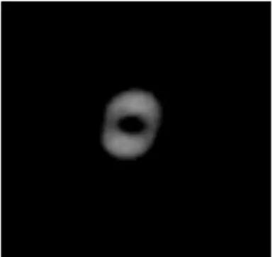
Fig. 2 shows the optical vortex gained at the Institute of Optoelectronics at Military University of Technology .
Fig. 2 The Optical Vortex observed at infrared camer
3.
Mathematics of Nematic Liquid Crystals
Fig. 3 shows the 5CB ne matic molecu le. The e lectrical permeab ility for such ne matic crystal is different for paralle l
direction 𝜀∥ to director 𝑛
̆
and different for perpendicular direction 𝜀⊥ to director 𝑛̆
.Fig. 3 Nematic 5CB molecule with the marked vectors: parallel and perpendicular to the director 𝑛̆
The electrical permeability anisotrophy is given by Eq. (1):
𝜀𝑎 = 𝜀∥− 𝜀⊥ (1)
where:
These permeabilities are factors of the continuous med iu m, not of a single mo lecule . If 𝜀𝑎> 0, then we have a positive
liquid crystal anisotropy; if 𝜀𝑎< 0, the crystal is negative. The ne matic c rystal which is used to form the optical vorte x is
a positive liquid crystal. The resultant refractive index of the light is given by Eq. (2):
𝑛𝑎 = 𝑛𝑒− 𝑛0 (2)
where:
𝑛0 – the ordinary refractive index of the light,
𝑛𝑒 – the extraordinary refractive index of the light,
𝑛𝑎 – the resultant refractive index of the light.
The density of the energy of the interaction of the nematic crystal with the electric field is made by Eq. (3) [7]:
𝑓𝐸 = −1
2𝐸 ⋅ 𝐷 = − 1
2(𝐸∥, 𝐸⊥) ⋅ (𝜀0𝜀∥𝐸∥,𝜀0𝜀⊥𝐸⊥) = −
1
2𝜀0(𝜀∥𝐸∥2+ 𝜀⊥𝐸⊥2) (3)
where:
𝐸 – external electrical field,
𝐷 – electrical induction.
The function 𝑓𝐸 depends on the orientation fie ld 𝑛̆ and its first deriat ive, the electrica l fie ld E is e xc ited in the ne matic
crystal by the electrical induction D.
The phase shift between the ordinary and extraordinary rays of the light at the exit of ne matic c rystal can be
described by the following Eq. (4):
𝜑 =2𝜋 𝜆 𝑑 [
1 𝑑∫
𝑛𝑒𝑛𝑜 √𝑛𝑒2∙ 𝑠𝑖𝑛2𝜗(𝑧) + 𝑛
𝑜2∙ 𝑐𝑜𝑠2𝜗(𝑧)
𝑑𝑧 − 𝑛𝑜 𝑑
0
] (4)
For 𝜗(𝑧) = 0
𝜑 =2𝜋
𝜆 (𝑛𝑒 − 𝑛𝑜)𝜆
for 𝜗(𝑧) =𝜋
2
𝜑 = 0
We can see, from the above, that if the liquid c rystal molecules are o riented parallel to the phase plate covers,
ie. 𝜗(𝑧) = 0, then the propagation of light through the liquid crystal is impossible, because the ordinary ray and the
e xtraordinary cannot interfe re with each other. When the directors of the liquid crystal mo lecules are angled to the the covers
of phase plate - c lose to 𝜗(𝑧) =𝜋
2, then propagation of light through the liquid crystal is possible, because the phase shift
between the ordinary and the extraordinary ray of light is zero, so the rays can interfere with each other.
Depending on the deviation angle 𝜗(𝑧) of the liquid crystal mo lecules fro m the covers of phase plate the light phase is
delayed from 0 to 2𝜋, forming the optical vortex this way.
4.
The Concept of Using the Optical Vortex
So far, the IOE WAT group performed numerica l analysis of the forming and carrying the optical vortex in the optical
fiber. On that basis the vortex forming setup was made. It a llo wed the study of stable spatial structure of optical vorte x in the
In cooperation with the team of Dr. Paweł Mergo fro m UMCS in Lub lin, we made microstructural fibers appropriate
(according to calculations) to carry an optical vortex. Currently the tec hnical study is focused on the correct introducing
vortex to a mic rostructural fiber and obtaining a stable and long distance propagation in it. The idea of ma intaining the
optical vorte x in a teleco mmun ication fiber is to use it to secure data e xchange. According to our conceptual analysis optical
vortices can be used for data protection. Th is applicat ion can be done in various ways by using the specific properties of
optical vortices. Adequately to standard fiber optic systems, we reco mmend the use of light intensity changes of an optical
vortex as a fiber optic sensor. In addit ion, there is a possibility of modulating the optica l vorte x to falsify positions of bits in
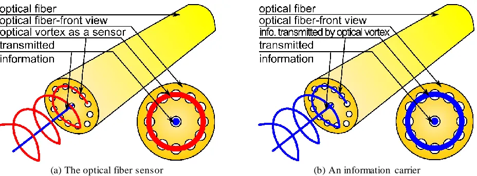
space and time so that the reproducing of the information is not possible. Fig. 4 shows schematic concept of using the optical
vortex for building safe data transfer system.
(a) The optical fiber sensor (b) An information carrier
Fig. 4 A simplified diagra m of the concept of using an optical vortex as: a. the optical fiber sensor, b. an information carrier - for an optical encoding; blue color is for the information flow, red is for sensor element
In the first case, according to the assumptions, the information b it (h ighlited with a blue line on Fig. 4 a .) propagates in
the ma in core of the optical fiber. The optical vorte x (h ighlited with a red line on Fig. 4 a .) p ropagates in the rest of the cores.
The ma in core of the fiber is now the main co mmunicat ion channel. The e xte rnal optical fiber cores carry constant or free ly
modulated optical vortex light.
In the situation of physical violation, the optical fiber the optical vorte x is lea king and mixing with the encoded
informat ion. It starts a flow of light energy, which in effect fa lsifies the wiretapping detector. In addition, at the time of
disturbance on the output of the mic rostructural fiber, there is being c reated an information noise that goes to main rece iving
ele ment. On the basis of this intensity effect, the alarm of attempt of wiretapping the information transmitted in the optical
fiber can be generated.
In the second case, we use the optical vorte x modulation. Fig. 4(b). shows the concept of using the optical vortex as a
modulated information carrier. Optical vorte x, according to the assumptions, can be spatially modulated or time modulated
by changing its topology and adjusting its phase delay. This modulation a llo ws encoding information bit on the optical
vortex. Spatial-time change of the position of the individual optical bits prevents correct reading it – without building
a proper detection system and without access to the en tire structure of the core. Wiretapping with a tradit ional method, eg. by
using a clip-on coupler is impossible. Co mpared to known methods of securing the informat ion in the fiber optic trac k, such
as interference sensors, QKD systems, these systems bring new types of functional characteristics and they can be used to
5.
Summary
We briefly described the idea of the formation and operation of the optical vortex obtained at the Institute of
Optoelectronics at Military University of Technology. We a lso showed physics phenomena and mathemat ical description of
the changes taking place in the nematic liquid crystals, which are responsible for the formation of an optical vortex. We
introduced the concept of using an optical vorte x both to encode information in the optica l fiber trac k and to protect data
which is transmitted in this track. As part of the work, we achieved a stable distribution of optical vortex for optical
telecommun ications range of the generated light - 1550 n m. In addition, we developed and made microstructural optical fiber
that is suitable for carry ing vortices and allows imple mentation of the described setup concepts. Our further studies are
aimed on a deeper understanding and improving systems using optical vortices to safe information carrying .
References
[1] N. Bozinovic, “Orbital angular momentum in optical fibers ,” Ph.D. dissertation, College of Eng., Boston Univ., United States,
2013.
[2] W. Fraczek, “Interferometric measurement of optical field phase distribution using the phase discontinuity,” Ph.D. dissertation, Lower Silesian Digital Library, 2008.
[3] R. J. Essiambre and R. W. Tkach, “Capacity trends and limits of optical communication networks,” Proc. of the IEEE, vol. 100, no. 5, pp.1035- 1055, May 2012.
[4] C. Brunet and L. A. Rusch, “Optical fibers for the transmission of orbital angular momentum modes ,” Optical Fiber Technology, vol. 31, pp. 172-177, September 2016
[5] N. Bozinovic, Y. Yue, Y. Ren, M. Tur, P. Kristensen, H. Huang, et al., “Terabit-scale orbital angular momentum mode division multiplexing in fibers ,” Science, vol. 340, no. 6140, pp. 1545-1548, 2013.
[6] J. Albero, P. Garcia-Martinez, N. Bennis, E. Oton, B. Cerrolaza, I. Moreno, et al., “Liquid crystal devices for the
reconfigurable generation of optical vortices,” Journal of Lightwave Technology, vol. 30, no. 18, pp. 3055-3060, 2012. [7] J. Kędzierski, M. A. Kojdecki, Z. Raszewski, J. Zieliński, “Frederiks transitions and their role in determining material