A SIMPLE SPEED CONTROL TECHNIQUE AND
PULSATING TORQUE ELIMINATION METHOD IN A
BRUSHLESS DC MOTOR
Jawad Faiz
Department of Electrical and Computer Engineering, Faculty of Engineering University of Tehran, Tehran, Iran
M. AboulghasemianAzami
Department of Electrical Engineering, Faculty of Engineering University of Tabriz, Tabriz, Iran
M. Moallem
Department of Electrical Engineering, Isfahan University of Technology, Isfahan, Iran
(Received: March 11, 1998 - Accepted in Revised Form: September 30, 1999)
This paper presents a theoretical derivation and computer simulation of an optimal
Abstract
speed controller for a brushless dc motor using feedback from a linear model running in parallel with the inverter-fed model. The intent of the feedback from the linear model is to eliminate torque ripples from the inverter drive. A nonlinear model of such a motor, transformed into a linear model by a local dipheomorphism (defined in section 2) and a new model is introduced in order to eliminate the undesirable effects of the inverter harmonics.
Speed Control, Pulsating Torque, Brushless DC Motor
Key Words
dcn±U±Ç« ð½ ºAoM ³®¼´M Sîow ²k®® ¤oT® ð½ ºoU±¼P«B ºpBw³¼L{ ° ºo ¯ ZBT®TwA ³§B « ½A
²k¼ña
ǽA /SwA ²kÇ{ ²jB TwA ºoUn±®½A ³½m U BM ºpA±« » i ¤k« ðMk¼ pA ¬C nj ³ ,kµj»« ³ÄAnA An ðM°nB] ¬°kM ð½ BM ºn±U±« ¼®a » io¼ ¤k« /k® »« me An oUn±®½A ³ od« pA »{B¯ n°BTz£ ºB´]±ªU » i ¤k« ðMk¼ J±¦ «Bǯ RAoYA BU SwA ²k{ » oí« ºk½k] ¤k« ° ²k{ ¥½kLU » i ¤k« ³M »í ±« dipheomorphism /k® me An oUn±®½A ºB´ñ¼¯±«nBµINTRODUCTION
R apid progress in microele ctronic and power electronic devices have creat ed a remarkable cha nge in t h e co nt ro l a nd a p plicat io ns o f e l e c t r ic a l m o t o r s. P e r m a n e n t m a gn e t synchronous mot or (P MSM) drives progre ss h a ve be e n du e t o t h e p r o gr e ss o f p o we r e le ct r o n ics. T h e r e a r e , o f co u r se , ma n y advantages such as high efficiency and reliability in such motors. A high ene rgy P MSM is ideal for a drive with a large torque, because of high e fficie ncy and lo w cost . U sing a rare e art h permanent magnet material in PMSM leads to a large stat or curre nt with no demagnetization effect.
The present technological tendency is toward a full digit al control of spee d and position of brushle ss dc drives [1,2]. The advant age s of microprossesor lie in computat ion ability and data storing capabilit y which can be use d for modification, and prediction of the feed-forward lo o p s. A go o d dyn a mic p e r fo r ma nce a n d stability of PMSM can be acheived by a digital control technique.
methods have been proposed in [4]: the first is base d on t he st at e sp ace an d t he se cond is based upon the theory of the variable structure systems.
T h is p a p e r p r e se n t s a sp e e d co n t r o l t e chn ique for a br ushle ss dc mo t o r wh ich e liminat e s pulsating torque . T he pro pose d technique is a simple and at the same time an efficient one. A nonlinear model of brushless dc mot or is transformed int o a line ar mode l by a local dipheomorphism (define d in se ction 2) and st at e fe e d-back; t h e n a vo lt a ge so u rce inverter is added to the model. To eliminate the undesirable effects of the inverter harmonics, a new model is introduced. It will be realized that t h e t or que r ipp le s dimin ish a nd t h e spe e d app roach st e a dy sta te mo d e wit h op timum performance.
NONLINEAR MODEL OF STATE VARIABLES
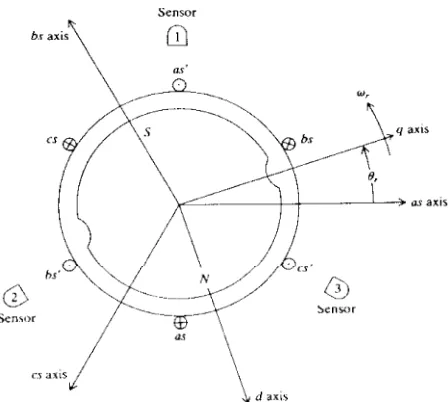
A brushle ss dc mot or (BD CM ) consist s of a PMSM itself, an inverter and a position sensor. Generally a BDCM is supplied by an ac source, its performance is similar to a shunt dc motor. A typical BD C M is shown in F igure 1. Thre e windings of the stator are arranged 120 degrees a pa rt , e a ch su pp lie d fro m o n e p ha se o f a three -phase supply. Inte raction be twe en t he r e sult e d ro ta ting fie ld a nd t he r ot or fie ld developes electromagnetic torque on the shaft of the motor. The state equations of the BDCM are as follows [5,6]:
dqr/dt= wr
dwr/dt=(1/J)(P/2)[(3/2)(P/2)( lÅmiqsr+(L d-Lq) idsriqsr)-Bm(2/p)wr-T1(t)]
diqsr/dt=[vqsr-rsiqsr-Ldwridsr-lÅmwr]/Lq
(1) didsr/dt=[vdsr-rsidsr+Lqwriqsr]/Ld
I n o r d e r t o t r a n sfo r m t h e n o n lin e a r equation, into exact linear equations, change of variables are required. The state equations are as follows:
(2) x
− =f(x)+G(x)v
Figure 1.A typical BDCM.
To simplify it, the state variables are defined as x1, x2, x3 and x4, the inputs as u1 and u2 and coefficients as ki:
k1=(1/J)(P/2)(3/2)(P/2) lÅm k2=(1/J)(P/2)(3/2)(P/2)(L d-Lq) k3=(1/J)B m
k4=(1/J)(P/2) k5=rs/Lq k6=L d/Lq k7=lÅm/Lq k8=rs/Ld k9=L q/Ld q1=1/Lq
(3) q2=1/Ld
The system of state equations will be: px1=x2
px2=k1x3+k2x3x4-k3x2-k4T1(t) px3=q1u1-k5x3-k6x2x4-k7x2
(4) px4=q2u2-k8x4+k9x2x3
from differential geometry are noted [8].
___________ Let f and g be two vector fields on Definition 1:
Rn, t he Lie bracke t of f and g is t hird vector field defined by:
(5) [f,g]=êg.f-êf.g
where êg and êf are Jacobian matrices of f and g.
___________ A linearly independent set of Definition 2:
vector fields {f1,f2,...,fn} is said to be involutive, if, there are scalar functionsaijk(x):RnØR such that:
(6) [fi,fj]=S aijk(x) fk(x) "ij
___________ A function ä:RnØRn, defined in a Definition 3:
region W, is called a dipheorphism if it is smooth and if its inverse ä-1 exists and is smooth.
T he fo llo win g n e ce ssa ry a n d sufficie n t conditions must be satisfied for the existence of transformation [7,9,10]:
___________ The nonlinear system of Eq. 2 canTheorem 1: be transformed into the following linear system: (7) y
− =Ay+Bv where
and t he st at e variable s x1, x2, x3, x4 lie in a sufficiently small open neighborhood U of the o rigin in R4, if, a nd on ly if, t h e fo llowin g conditions hold on U[10]:
a) The se t C= {g1,[f,g1],( ad2f,g1),g2} has full rank.
b) The set C1={g1,[f,g1],g2,[f,g2]} is involutive. c) The span of C1is equal to the span of C1úC.
It can be proved that all three conditions of theorem 1 have been satisfied for BDCM. It is n o w p o ssible t o co n st r u ct a n o n -u n iq u e transformation for the same variables using the
second theorem.
___________ If the nonlinear system 2 isTheorem 2: T-related to the system on U, then:
a) ÃTj/Ãuk=0, for j=1,2,3,4 and k=1,2.
b) the 2x2 matrix [ÃTj/Ãuk], j= 5,6 and k= 1,2 is nonsingular on U.
<dTm, gi>0, m=1,2 and i=1,2, where <dTm,gi>= ÃTm/Ãxi-gi
and <dTm,f>=T m+1, m=1,2 <dT3,f+Gu>=T 5
<dT4,f+Gu>=T 6
Solution of the se e quations le ads t o t he ve ct o r fie ld T , wh ich ca n n o n -u n iqu e ly transform the nonline ar equations 4 into t he linear equation 7:
(8)
The final linear equations of the motor are as follows:
y
− 1=y2
y
− 2=y3
(9) y
− 3=v1
y
− 4=v2
The mathematics associated with the control theory may be left out with only final results (Eqs. 8 and 9) given as applicable to the motor. If this mathemat ical part of the paper is not interesting for some reade rs, they can leave it a n d k e e p in min d t h a t E qs. 8 a n d 9 a r e linearization of Eqs. 1.
SPEED CONTROL
four state variables and two inputs. To define the feedback loop gains, a 4x2 matrix must be determined. By poles placement, there are only four options closed-loop feedback gain matrix. Therefore a method must be chosen such that t h e e igh t e le me n t s o f t h e ma t r ix ca n be de t e r min e d by a syst e ma t ic a n d o p t ima l technique. An optimal control theory method [11], which is applicable in linear syst ems, is used here in order to obtain the feedback gain. F or such a syst e m, a quadrat ic performance criterion in term of the states and inputs must be always minimized. Using this constraint, the feedback matrix can be uniquely defined. The performance criterion of the system is:
(10)
where Q=diag (q1q2q3q4) and R=diag (r1 r2). U sing the elements of the two latter matrices, the locus of the poles of the closed-loop system can be varied. To control the speed, the largest we ight is given t o t he first st ate variable. It means that the variations of the speed integral has bee n minimized, and the final response is achieved. The fourth variable of the matrix Q , we ight e d id sr, is inde p e nde nt of re maining variables and its eigenvalue can be varied with any weight. Consequently the matrix Q is used to control the system:
(11) Q=diag [107 1 1 103]
M at rix R is cho se n a s u nit mat rix. Th e reason is to limit inputs, in order to keep them in the reasonable and acceptable limits. U sing these two matrices, the Riccate's matrix can be obtained for the optimal control.
(12) -K− =KA+A ÅK+KBR -1BÅK+Q
From this matrix, the feedback gain matrix can be de t e r min e d fo r op t imal co nt r ol o f t h e system:
(13) G= -R-1BÅK
TORQUE
Inverter-fed electrical motors contain various harmonics which produce ripple on the shaft of motor. Many have paid attention to eliminating this ripple. Here a new method is introduced for e limin a t in g t h e r ip p le . A s t h e fo llo win g equation indicates:
(14) Te=J(2/P)p wr+Bm(2/P)wr+T1
The e le ct romagnet ic torque is t he sum of angular accele ration, angular spee d and load torque with constant coefficients. Performance put limit s on t he variat ions of the angu lar acceleration and spe ed of t he motor and it is always required to minimize the range of these variations. Consequently the electromagnetic torque also has a limited variations.
SIMULATION RESULTS
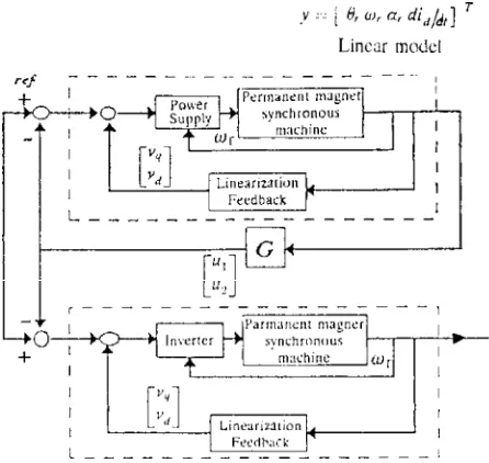
Blo ck dia gr am o f F igu re 2 is t he base fo r simulation of the optimal spee d cont rol. The sampled speed and currents are multiplied by a gain G, obtained from the optimum control, and suit able inp ut s v1 and v2 o f t he syst e m are determined to control the motor. As shown in Figure 2, coe fficient x1in matrix Q , de noting the mot or position, is chosen a large number which puts limit on the torque to be variations. By in ve r se t r a n sfo r ma t io n o f t h is se t o f va ria ble s, the ma in var iable s of t he mot or control the speed.
Figure 2.Block diagram of the optimal speed control of inverter-fed motor.
The BD CM , with the paramet ers give n in Table 1, is simulated.
T he t hr e e p ha se ( a s, bs a nd cs) o ut pu t volt age s wave forms of inve rte r for no-load condition have been presented in Figure 3. To co n t r o l t h e sp e e d , it is a ssu me d t h a t a t st e a d y-st a t e mo de o f o p e r a t io n a ll st a t e variables are zero. The aim is to obtain a speed equal to 160 rad/s. To achieve this the reference signal is set on the spe e d e qual to 160 rad/s. The spee d raise s unt il a re quire d le ve l and a load torque equal to 0.14 Nm is then applied on the shaft of the motor. Applying the load motor reduces the spe ed up to the reference spe ed. Gain matrix, G, for the proposed motor is [12]:
For the sake of comparison, the output
TABLE 1. The Simulated BDCM Parameters. Bm J
P lm L1s Lb La Rs
Nms/rad kgm2
-Wb mH mH mH Ohm
0 0.0001 4
0.0826 1.10
0 7.33 3.34
Figure 3.O u t p u t vo lt a ge wa ve fo r m s o f in ve r t e r fo r no-load condition.
characteristics of the open-loop system are also sketched on the same figures. It is clear that: 1. Applying a load t orque on t he open-loop system causes a large speed drop;
Figure 4.To rqu e/time char acter istic for optim al sp eed control, including extended scale curve.
Figure 5.Torque/time characteristic for open-loop system.
variables in the closed-loop system.
Pe rformance of the optimal syst em can be re alize d by comp ar in g t he t wo se t s of t he curves. Figure 4, electromagnetic torque/time for opt imal control shows ve ry large torque variation immediat ely after t = 0 up t o t= 0.15 seconds, the extended scale figure is also shown in order to clarify this. Figure5, electromagnetic torque/time for open loop shows no such torque variation but a continuous torque ripple. This comparison betwe en ope n- and closed-loop performance must be made between Figure 5
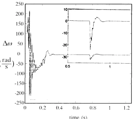
Figure 6.Spe ed e rro r cu rve for op tima l speed co ntro l, including extended scale curve.
Figure 7.Speed/time characteristic for open-loop system.
and the ext ended scale curve in Figure 4. It is e vide nt t h a t t h e con t r olle r offe rs ove r all o p e r a t in g imp r o ve m e n t fo r st a r t in g a n d steady-state performance of the motor.
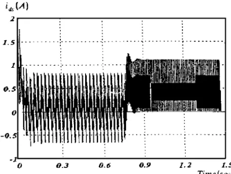
Figure 8.Varia tion of stator d -axis cu rrent for optimal control system.
Figure 9.Varia tion of stator q -axis cu rrent for optimal control system.
Figure 10.St ato r q-axis cu rr ent for op en -loop con tr ol system.
Figure 11.St ato r d-axis cu rr ent for op en -loo p con tr ol system.
the current ripple during the steady-state mode o f o p e r at io n wh ich is a sign ifica nt r e su lt obtained using this control system.
Figure 8-11 present the currents variations for optimal control and ope n-loop syste ms. Co mpa rison of th e se figur e s indicat e s t he advantage of t he optimal close d-loop syst em from eliminating the ripple and approaching the required speed points of view.
Alt hough it seems t hat a simplistic vie w of the t or que r ipple issue s has be e n t ake n in BD CM , t he obta ine d mode l ca n some h ow follow a be haviour of the re al machines. F or instance such a model has been used in [10] and [13], and confirmed by the experimental results, to our best knowledge, eliminating the torque using an optimal control in BDCM has not been presented in the literature and comparison with others work is not possible.
CONCLUSIONS
of the inve rte r harmonics, a mode l wit hout noise was used with an inverter-fed real motor mode l. This le ads t o t he e liminat ion of t he harmonic e ffe ct on the syste m output. The ripple of the motor diminished and motor kept the constant speed.
ACKNOWLEDGEMENTS
The authors are indebted to Tabriz U niversity for financial support of the project.
NOTATION
rotor angle qr
rotor angular speed wr
time t
moment of inertia of motor J
number of poles P
magnetization flux-linkage lÅm
q and d axis current of stator iqsr, idsr
d-axis inductance Ld q-axis inductance Lq load torque Tl
q and d axis voltage of stator vqs , vds
respectively stator resistance rs
damping coefficient Bm
feedback gain matrix G
electromagnetic torque Te
operator (d/dt) p
leakage inductance of stator Lls
REFERENCES
L iu , T . H ., Y o u n g, C . M . a n d L iu , C . H . , 1.
"Microprocessor-based controller design and simulation for a permanent magnet synchronou s motor drive", IEEE Trans. on Industrial Electronics, Vol. 35, No. 4, pp. 516-523, (Nov. 1988).
Karunadasa, J. P. and Renfrew, A. C., "A flexible fast 2.
digital controller for a bru shless dc motors",5th IEE InternationalConference on Electrical Machines and Drives,London, pp. 213-217, (September 1990). Lehuy, H., Perret, R. and Fewillet, R.,"Minimization of 3.
torque ripple in brushless dc motor drive",IEEE Trans. on Ind us tri a l Appl i c a ti ons, V o l. 2 2 , N o . 4 , pp. 748-756, (1986).
Low, T. S., Tseng, K. J., Lee, T. H. and Lock, K. W., 4.
"Two strategy for the instantaneou s torque control of permanent-magnet brushless dc drives",IEE Proc., Pt. B, Vol. 137, No. 6, pp. 355-363, (1990).
Krause, P. C., "Analysis of electric machinery", IEE E 5.
Press, (1993).
Kr au se , P. C., N u ccer a , R . R ., Kre ft a , R . J . a n d 6.
Wa synczu k, O ., "Ana lysis of a pe rm an en t-ma gn et synchronou s machine su pplied from a 180Üinverter with phase control",IEEE Trans. on Energy Conversion, Vol. EC-2, No.3, pp. 423-431, (September 1987). H u n t , L. R ., Su , R . a n d M e ye r , G ., "D e sign fo r 7.
multi-input nonlinear systems", Differential Geometric Control Theory, Cambridge, M:Birkhauser, (1982). Slotine, J. J. and Li, W., "Applied nonlinear control", 8.
Prentice Hall, (1991).
Kakubczky, B. and R espondek, W., "O n linearization 9.
of control systems",Bulletin de L'academic Polonasise des Science, Seri es des Sciences Mathematiques, Vol. XXVIII, No. 9-10, pp. 517-522, (1980). Fam ou ri, P ., "Cont rol of linear pe rmane nt-magnet 10.
bru shless dc motor via exact linearization method", IEEE Trans. on Energy Conversion, V ol. 7, No . 3, pp. 544-551, (September 1992).
Friedlan d, B., "Con trol syste m design", New Yo rk, 11.
McGraw-Hill, (1987).
Fa iz, J., Aza mi, M.A., Keyha ni, A. an d Pr oca, A., 12.
"Closed-loop control stability for permanent magnet synchronous motor",International Journal of Electrical Power a nd Energy System s, V o l. 1 9 , N o . 5 , pp. 331-337, (1997).
H e ma ti, N ., Tho rp J. S. an d Leu , M. C., "R o bu st 13.