InTrans Project Reports Institute for Transportation
12-2014
Rapid Replacement of Bridge Deck Expansion
Joints Study – Phase I
Charles T. Jahren
Iowa State University, [email protected]
Adam Michael Miller
Iowa State University, [email protected]
Follow this and additional works at:http://lib.dr.iastate.edu/intrans_reports Part of theCivil Engineering Commons
This Report is brought to you for free and open access by the Institute for Transportation at Iowa State University Digital Repository. It has been accepted for inclusion in InTrans Project Reports by an authorized administrator of Iowa State University Digital Repository. For more information, please [email protected].
Recommended Citation
Jahren, Charles T. and Miller, Adam Michael, "Rapid Replacement of Bridge Deck Expansion Joints Study – Phase I" (2014).InTrans Project Reports. 110.
Rapid Replacement of Bridge Deck Expansion Joints Study – Phase I
Abstract
Bridge deck expansion joints are used to allow for movement of the bridge deck due to thermal expansion, dynamics loading, and other factors. More recently, expansion joints have also been utilized to prevent the passage of winter de-icing chemicals and other corrosives applied to bridge decks from penetrating and damaging substructure components of the bridge. Expansion joints are often one of the first components of a bridge deck to fail and repairing or replacing expansion joints are essential to extending the life of any bridge. In the Phase I study, the research team focused on the current means and methods of repairing and replacing bridge deck expansion joints. Research team members visited with Iowa Department of Transportation (DOT) Bridge Crew Leaders to document methods of maintaining and repairing bridge deck expansion joints. Active joint replacement projects around Iowa were observed to document the means of replacing expansion joints that were beyond repair, as well as, to identify bottlenecks in the construction process that could be modified to decrease the length of expansion joint replacement projects. After maintenance and replacement strategies had been identified, a workshop was held at the Iowa State Institute for Transportation to develop ideas to better maintain and replace expansion joints. Maintenance strategies were included in the discussion as a way to extend the useful life of a joint, thus decreasing the number of joints replaced in a year and reducing the traffic disruptions.
Keywords
Bridge decks, Expansion joints, Highway maintenance, Joints (Engineering), Maintenance, Service life
Disciplines
Civil Engineering
Comments
Rapid Replacement of
Bridge Deck Expansion
Joints Study – Phase I
Interim Report
December 2014
About InTrans
The mission of the Institute for Transportation (InTrans) at Iowa State University is to develop and implement innovative methods, materials, and technologies for improving transportation efficiency, safety, reliability, and sustainability while improving the learning environment of students, faculty, and staff in transportation-related fields.
About CMAT
The mission of the Construction Management and Technology (CMAT) Program is to improve the efficiency and cost-effectiveness of planning, designing, constructing, and operating transportation facilities through innovative construction processes and technologies.
Disclaimer Notice
The contents of this report reflect the views of the authors, who are responsible for the facts and the accuracy of the information presented herein. The opinions, findings and conclusions expressed in this publication are those of the authors and not necessarily those of the sponsors.
The sponsors assume no liability for the contents or use of the information contained in this document. This report does not constitute a standard, specification, or regulation.
The sponsors do not endorse products or manufacturers. Trademarks or manufacturers’ names appear in this report only because they are considered essential to the objective of the document.
ISU Non-Discrimination Statement
Iowa State University does not discriminate on the basis of race, color, age, ethnicity, religion, national origin, pregnancy, sexual orientation, gender identity, genetic information, sex, marital status, disability, or status as a U.S. veteran. Inquiries regarding non-discrimination policies may be directed to Office of Equal Opportunity, Title IX/ADA Coordinator, and Affirmative Action Officer, 3350 Beardshear Hall, Ames, Iowa 50011, 515-294-7612, email [email protected].
Iowa DOT Statements
Federal and state laws prohibit employment and/or public accommodation discrimination on the basis of age, color, creed, disability, gender identity, national origin, pregnancy, race, religion, sex, sexual orientation or veteran’s status. If you believe you have been discriminated against, please contact the Iowa Civil Rights Commission at 800-457-4416 or the Iowa Department of Transportation affirmative action officer. If you need accommodations because of a disability to access the Iowa Department of Transportation’s services, contact the agency’s affirmative action officer at 800-262-0003.
Technical Report Documentation Page
1. Report No. 2. Government Accession No. 3. Recipient’s Catalog No.
InTrans Project 13-451
4. Title and Subtitle 5. Report Date
Rapid Replacement of Bridge Deck Expansion Joints Study – Phase I December 2014
6. Performing Organization Code InTrans Project 13-451
7. Author(s) 8. Performing Organization Report No.
Adam M. Miller and Charles T. Jahren
9. Performing Organization Name and Address 10. Work Unit No. (TRAIS)
Institute for Transportation Iowa State University
2711 South Loop Drive, Suite 4700 Ames, IA 50010-8664
11. Contract or Grant No.
12. Sponsoring Organization Name and Address 13. Type of Report and Period Covered
Iowa Department of Transportation 800 Lincoln Way
Ames, IA 50010
Federal Highway Administration U.S. Department of Transportation 1200 New Jersey Avenue SE Washington DC 20590
Phase I Interim Report
14. Sponsoring Agency Code SPR RB33-013
15. Supplementary Notes
Visit www.intrans.iastate.edu for color pdfs of this and other research reports.
16. Abstract
Bridge deck expansion joints are used to allow for movement of the bridge deck due to thermal expansion, dynamics loading, and other factors. More recently, expansion joints have also been utilized to prevent the passage of winter de-icing chemicals and other corrosives applied to bridge decks from penetrating and damaging substructure components of the bridge. Expansion joints are often one of the first components of a bridge deck to fail and repairing or replacing expansion joints are essential to extending the life of any bridge.
In the Phase I study, the research team focused on the current means and methods of repairing and replacing bridge deck expansion joints. Research team members visited with Iowa Department of Transportation (DOT) Bridge Crew Leaders to document methods of maintaining and repairing bridge deck expansion joints. Active joint replacement projects around Iowa were observed to document the means of replacing expansion joints that were beyond repair, as well as, to identify bottlenecks in the construction process that could be modified to decrease the length of expansion joint replacement projects.
After maintenance and replacement strategies had been identified, a workshop was held at the Iowa State Institute for Transportation to develop ideas to better maintain and replace expansion joints. Maintenance strategies were included in the discussion as a way to extend the useful life of a joint, thus decreasing the number of joints replaced in a year and reducing the traffic disruptions.
17. Key Words 18. Distribution Statement
bridge deck—bridge joint repair—bridge maintenance—expansion joint replacement
No restrictions.
19. Security Classification (of this report)
20. Security Classification (of this page)
21. No. of Pages 22. Price
Unclassified. Unclassified. 71 NA
RAPID REPLACEMENT OF BRIDGE DECK
EXPANSION JOINTS STUDY
–
PHASE I
Interim Report December 2014
Principal Investigator Charles T. Jahren, Professor
Construction Management and Technology Institute for Transportation, Iowa State University
Research Assistant Adam M. Miller
Authors
Adam M. Miller and Charles T. Jahren
Sponsored by
the Iowa Department of Transportation and the Federal Highway Administration
(InTrans Project 13-451)
Preparation of this report was financed in part
through funds provided by the Iowa Department of Transportation through its Research Management Agreement with the
Institute for Transportation
A report from
Institute for Transportation Iowa State University 2711 South Loop Drive, Suite 4700
TABLE OF CONTENTS
ACKNOWLEDGMENTS ... vii
EXECUTIVE SUMMARY ... ix
CHAPTER 1. INTRODUCTION ...1
1.1 Objectives ...1
1.2 Report Organization ...1
CHAPTER 2. DETERIORATION PATTERNS AND MAINTENANCE EFFORTS ...2
2.1 Chapter Overview ...2
2.2 Introduction ...2
2.3 Research Methodology ...2
2.4 Sliding Plate Expansion Joints ...2
2.5 Strip Seal and Compression Seal Joints ...8
2.6 Finger Joints and Modular Expansion Joints ...16
2.7 Integral Abutment Joints ...21
CHAPTER 3. CURRENT JOINT REPLACEMENT PRACTICES ...23
3.1 Chapter Overview ...23
3.2 Introduction ...23
3.3 Northbound I-380 Joint A Replacement ...23
3.4 US 18 over the Wapsipinicon River ...34
CHAPTER 4. RAPID RELACEMENT OF EXPANSION JOINT WORKSHOP ...39
4.1 Introduction ...39
4.2 Summary of Previous Research Tasks ...39
4.3 Pertinent Iowa DOT Design Standards and Design Considerations ...42
4.4 Breakout Groups, Idea Discussion, and Ranking ...43
4.5 Workshop Results ...44
CHAPTER 5. CONCLUSION AND CONTINUING RESEARCH EFFORTS ...47
5.1 Conclusion ...47
5.2 Continuing Research Efforts ...47
REFERENCES ...49
APPENDIX A. WORKSHOP PARTICIPANTS, OVERVIEW, AND RESULTS ...51
LIST OF FIGURES
Figure 2.1. Large sections of a plate broken loose on northbound I-380 Exit 19A in Cedar
Rapids, Iowa ... 4
Figure 2.2. Gap forming between top of abutment and approach panel on the I-80 over I-35 west abutment ... 5
Figure 2.3. Rusted top plate beneath a raise plate showing relatively good condition on westbound US 20 over Catfish Creek in Cedar Rapids, Iowa ... 6
Figure 2.4. Extreme case of sliding plate joint maintenance ... 7
Figure 2.5. Strip seal joint ... 8
Figure 2.6. Compression seal joint ... 9
Figure 2.7. Badly weathered, but still functioning, strip seal joint ... 10
Figure 2.8. Strip seal joint with missing extrusion section ... 14
Figure 2.9. Compression seal joint with failed section of armoring ... 15
Figure 2.10. Silicoflex expansion joint example ... 16
Figure 2.11. Modular expansion joint ... 17
Figure 2.12. Neoprene trough below finger expansion joint ... 18
Figure 2.13. Exposed piling from slope erosion ... 19
Figure 2.14. Debris collection in modular expansion joint preventing full closure of the joint ... 19
Figure 2.15. New Iowa DOT standard detail for wing wall armoring ... 22
Figure 3.1. Northbound I-380 project location ... 24
Figure 3.2. Approximate locations of expansion joints ... 25
Figure 3.3 Typical I-380 concrete removal cross section ... 26
Figure 3.4 Aqua Cutter hydrodemolition machine ... 29
Figure 3.5. Joint A after hydrodemolition ... 30
Figure 3.6 Concrete remaining after hydrodemolition ... 31
Figure 3.7. Flexible shaft vibratory compactor ... 33
Figure 3.8. US 18 Over Wapsipinicon River project location ... 34
Figure 3.9. Typical US 18 removal cross section ... 35
Figure 3.10. Replacement paving notch plan ... 36
Figure 3.11. US 18 possible detour route ... 38
LIST OF TABLES Table 3.1. Construction task length by hour ... 28
ACKNOWLEDGMENTS
The authors would like to thank the Iowa Department of Transportation (DOT) for sponsoring this research as well as the Federal Highway Administration for state planning and research (SPR) funds used for this project.
The authors would like to thank the technical advisory committee for this project including Dean Bierwagen, Mark Carter, Dan Cramer, Matt Johnson, Linda Narigon, James Nelson, Steve Sandquist, Justin Sencer, and Wayne Sunday. A multitude of Iowa DOT, personnel too
numerous to list, were engaged on this project and the authors would like to thank each of them for their individual contributions.
EXECUTIVE SUMMARY
Bridge deck expansion joints are used to allow for movement of the bridge deck due to thermal expansion, dynamics loading, and other factors. More recently, expansion joints have also been utilized to prevent the passage of winter de-icing chemicals and other corrosives applied to bridge decks from penetrating and damaging substructure components of the bridge. Expansion joints are often one of the first components of a bridge deck to fail and repairing or replacing expansion joints are essential to extending the life of any bridge.
In this Phase I study, the research team focused on documenting the current means and methods of bridge expansion joint deterioration, maintenance, and replacement and on identifying improvements through all of the input gathered.
Research team members visited with Iowa Department of Transportation (DOT) Bridge Crew Leaders to document methods of maintaining and repairing bridge deck expansion joints. Active joint replacement projects around Iowa were observed to document the means of replacing expansion joints that were beyond repair, as well as, to identify bottlenecks in the construction process that could be modified to decrease the length of expansion joint replacement projects.
After maintenance and replacement strategies had been identified, a workshop was held at the Iowa State Institute for Transportation to develop ideas to better maintain and replace expansion joints. Maintenance strategies were included in the discussion as a way to extend the useful life of a joint, thus decreasing the number of joints replaced in a year and reducing the traffic disruptions.
The results of this phase of the research provide details about the types of failure experienced with expansion joints in Iowa, measures taken to repair and prevent these types of failures, current construction methods undertaken by contractors in Iowa, and hypothesized ways to improve methods of expansion joint repair and maintenance.
CHAPTER 1. INTRODUCTION
Bridge deck expansion joints are the components of a bridge that allow for movement of the bridge deck due to thermal expansion, dynamic loading, and several other factors. More recently, expansion joints have had a secondary function of preventing the passage of water. This water often contains deicing salts and other corrosive chemicals that are harmful to the substructure of the bridge.
Expansion joints are often one of the first components of a bridge to fail. Failure can be due to increased traffic loading, component fatigue, low quality work, or several other factors. Joint failure can lead to increased damage to bridge substructures including rust formation on metal bearings as well as increased spalling on precast beam ends, concrete abutments, and concrete piers. To prevent further bridge damage, joints are often repaired or replaced.
Joint replacements are particularly problematic construction projects, often requiring traffic closures to allow work completion. Traffic closures are undesirable and often require staged jobs and difficult working conditions. Completing work during low traffic periods, nights, and
weekends can help alleviate traffic concerns. However, it is challenging to complete a repair in a very short period of time or at night while still maintaining the necessary joint quality. Improved methods to rapidly repair and replace bridge deck expansion joints are desirable.
1.1 Objectives
The objectives of this research are two-fold, to both examine both current means and methods as well as develop new methods of replacing expansion joints. This research provides the Iowa Department of Transportation (DOT) with detailed information about the types of failure experienced by expansion joints, measures taken by the Iowa DOT to repair and prevent these types of failures, current construction methods undertaken by contractors in Iowa, and
hypothesized ways to improve methods of expansion joint repair and maintenance.
A significant portion of this research is focused on the current state of expansion joints and developing novel ideas to rapidly repair expansion joints, so some results may be contracted as future projects for more detailed evaluation.
1.2 Report Organization
CHAPTER 2. DETERIORATION PATTERNS AND MAINTENANCE EFFORTS
2.1 Chapter Overview
This chapter details the results of interviews with Iowa DOT bridge leaders regarding their field experience with joint deterioration and the maintenance efforts they pursue to extend the life of the bridge deck expansion joints in their specific districts. This chapter is organized by type of expansion joint. Each joint section discusses identified patterns of deterioration, maintenance methods utilized in extending the life of the expansion joint, and the indications that the maintenance crew leaders use to determine when maintenance or replacement may soon be needed.
2.2 Introduction
The Iowa DOT doesn’t have published guidelines that specifically state the maintenance to complete on expansion joints. Most actions are determined and completed at the discretion of the District engineer and the bridge maintenance crew leader. As such, the actions taken often remain largely unknown to the design engineers who will eventually be designing joint replacements.
2.3 Research Methodology
Deterioration patterns were documented primarily by field visits to Mark Carter, Iowa DOT District 6 Bridge Leader and a planned future visit to Greg Mize, Iowa DOT District 3 Bridge Crew Leader. At the writing of this report, the field visit with Greg Mize has been delayed due to heavy rainfall and flooding in the western portion of Iowa.
The maintenance efforts taken to correct deterioration patterns will be recorded during these field visits. Once both visits have been completed, interviews of the remaining bridge crew leaders will take place to verify the similarities between their operations and those of Districts 3 and 6 if deemed necessary by the technical advisory committee.
Four main groups of expansion joints were identified as being widely utilized by the Iowa DOT: sliding plate joints, strip seal and compression seal joints, modular and finger joints, and integral abutment joints. While other joint types have occasionally been utilized by the Iowa DOT, their usage was uncommon, largely untested, and not addressed during this study.
Sliding plate expansion joints are no longer utilized by the Iowa DOT for new construction. However, of the 1,000 bridges on the primary system that contain expansion joints, about a third still contain at least one existing sliding plate joint (Jim Nelson Personal Communication Dec. 4, 2013). Thus, the maintenance and rehabilitation of these joints are still of major concern for the immediate future.
2.4.1 Joint Deterioration
At the advanced age of most of the sliding plate joints, several problems are generally occurring. Since most of the sliding plate joints are already experiencing these types of deterioration, the age at which these problems occur was not discussed. Among the most common observed by the Iowa DOT maintenance personnel is a lack of movement in the joints.
After many years of sliding against one another, the two plates that form the joint start building up rust in between the plates. Eventually the rust between the plates build up to such a degree that the plates are fused together and the joint becomes immobile. These now fixed joints prevent the bridge deck from expanding or contracting as necessary and cause additional stresses to build up in both the abutment and the bridge deck. When stresses in the concrete become high enough, the joint eventually pulls free from the surrounding concrete.
According to Mark Carter, when the joints pull free they generally pull free from the abutment side of the joint. The damage can be anywhere from simply a steel plate pulling loose and needing removed from the joint to the extreme case where the abutment fails at its base where it connects the footing. The severity of the damage is usually somewhere between these two cases with the steel plate and a large section of concrete, but not the entire abutment, pulling free. The opposite case where the joint pulls free from the deck side is considerably less common but still occurs.
A second major point of failure with sliding plate joints is fatiguing of the steel plate. This damage is especially likely to occur in areas with considerably heavy truck traffic, especially if that traffic has increased from when the joint was originally installed.
Image: Adam Miller, ISU
Figure 2.1. Large sections of a plate broken loose on northbound I-380 Exit 19A in Cedar Rapids, Iowa
The joint shown, now replaced, was present on Exit 19A, Northbound I-380 in Cedar Rapids. A processing plant was noted a few blocks from the exit and the Iowa DOT inspector had observed a considerable amount of heavy truck traffic on that exit. Most of the joints along that exit
showed similar fatigue damage including one joint where nearly the entire top plate was missing.
2.4.2 Signs of Joint Failure
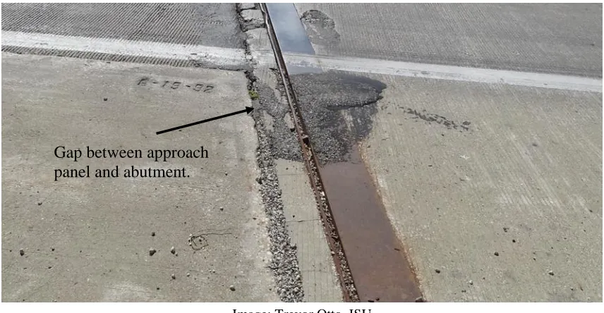
Image: Trevor Otto, ISU
Figure 2.2. Gap forming between top of abutment and approach panel on the I-80 over I-35 west abutment
Notice there is a gap (which is also filled with debris) forming between the approach panel and the top of the abutment. When initially constructed, these two slabs should be flush with only a small bond breaker between the panels.
Noise produced when driving over the joint can be another sign of joint failure. A sliding plate joint that is in good condition should make little noise when traffic passes over it. However, if the joint has pulled loose from the abutment, there is a sound described by Mark Carter as sounding “like a cannon being fired.” The louder the noise, the more movement is occurring in the joint.
Signs of fatigue damage are typical for many steel structures that are subjected to repetitive loads. Cracks along an expansion joint are important indications of incipient plate failure. Vertical movement of the top plate of the expansion joint can also be observed during the passage of traffic. There can, however, be some difficulties in observing fatigue cracks in the plate.
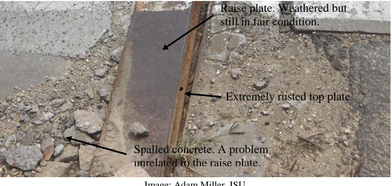
In past decades, joints were not always replaced as a part of a typical bridge overlay job. To match the new grade of the bridge deck to the grade of the expansion joint, a second steel plate, known as a raise plate, was welded to the top plate of the existing joint. While this solved the elevation problem, it did not add any structural capability to the steel plate.
Years later, the original top plates are now beginning to fatigue, but the damage is hidden under a raise plate that usually appears to be in relatively good condition. This can be seen in Figure 2.3 (before replacement), where a badly rusted top plate can be viewed beneath a top plate showing relatively good conditions.
Image: Adam Miller, ISU
Figure 2.3. Rusted top plate beneath a raise plate showing relatively good condition on westbound US 20 over Catfish Creek in Cedar Rapids, Iowa
The portion shown is along the shoulder section of the highway. The top plate had come loose previously and been removed across the entire two lanes of traffic of the joint.
2.4.3 Joint Maintenance Efforts
There are several aspects to consider when maintaining sliding plate expansion joints. These joints are not and never were designed to be watertight. Thus, maintenance measures never considered the need to make the joint watertight. Improving the joint beyond the original
condition was considered to be out of scope of maintenance efforts. Secondly, the main purpose is to allow the expansion and contraction of a bridge deck to prevent structural damage. Thus, the main goals in repairs of sliding plate expansion joints is to allow for the movement of the bridge deck and the passage of traffic while disregarding whether the joint prevents the passage of water.
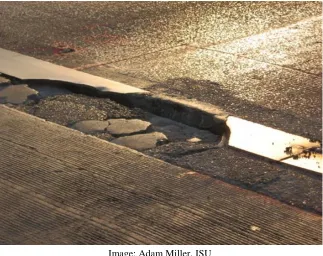
Damage where the joint has pulled loose from the abutment, or less commonly the bridge deck, is problematic. Such damage generally involves the removal of a substantial amount of concrete requiring a period of traffic closure to complete the repairs. These traffic closures are sudden and generally occur at a less than ideal time, requiring the roadway to be opened again in a rather short amount of time. To do this, the loose concrete and joint sections are removed in their entirety. The missing concrete and joint are then replaced by creating a flat open joint in the roadway. Essentially, the concrete is removed and new concrete is placed with a gap between the abutment and bridge deck allowing for bridge movement. An extreme case where both sides of the joint have broken loose is shown in Figure 2.4
Extremely rusted top plate Raise plate. Weathered but still in fair condition.
Image: Adam Miller, ISU
Figure 2.4. Extreme case of sliding plate joint maintenance
The gap in the joint appears small because the photo was taken on a summer day when the bridge was very near its expansion limit. This situation will likely not provide a smooth riding surface over the joint, but it still achieves the purpose of allowing for the movement of the bridge deck and the passage of traffic while still allowing the passage of water.
Under the short duration of the closures, placing a new joint is not a feasible option. This repair may not create a good joint, but it is a functional solution in the time allowed and will not allow significantly more damage from water passage than previously allowed.
In the case of fatigue damage where sections of the plate steel breaks off, a feasible repair strategy has not been identified. Mark Carter described in detail attempts to repair these joints to a like-new condition by welding in place replacement sections of plate steel. However, despite the considerable efforts to weld and reinforce these problematic sections of steel, the difficulty of providing a field weld of sufficient quality in these sections usually proved such repairs to be short-lived and the plate would soon be loose again.
When plates have fatigued and broken loose, they are monitored until the plate is loose enough to allow easy removal. Waiting to remove the failing section of plate can be beneficial for maintenance personnel. However, while a plate that has only just begun to crack and fail can be extremely difficult to remove, a plate that is extremely loose has the potential to fail entirely and become a hazard to traffic.
Figure 2.1 would be typical of what remains of a plate joint. The joint will no longer provide a smooth ride for traffic, but will still complete the main functions of allowing the movement of the bridge deck and the passage of traffic.
2.5 Strip Seal and Compression Seal Joints
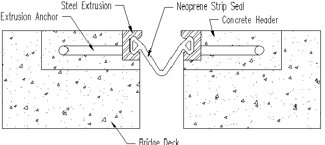
Strip seal and compression seal expansion joints are separate styles of joints that utilize a gland to prevent the passage of water through the expansion joint. In particular, a strip seal joint includes a gland, generally neoprene, that is mechanically locked in place through the use of steel extrusions embedded in the concrete header on either side of the expansion joint. An example of a strip seal joint is shown in Figure 2.5.
[image:22.612.148.467.253.396.2]Not to scale. Drawing: Adam Miller, ISU; adapted from D.S. Brown Company (dsbrown.com)
Figure 2.5. Strip seal joint
Not to scale. Drawing: Adam Miller, ISU; adapted from Watson Bowman Acme Corp. (wbacorp.com)
Figure 2.6. Compression seal joint
Although the Iowa DOT is phasing out the use of compression seals, they are still installed occasionally and a considerable number are currently in use. Both strip seals and compression seals have similar deterioration patterns and are addressed together in the next section.
2.5.1 Joint Deterioration
The most common problem with strip seal and compression seal joints is the failure of the
neoprene glands that are placed in the joints. In Iowa, this typically occurs after about 15 years of service for a strip seal joint and 10 years of service for a compression seal joint.
A failed seal is not a failure of the structural integrity of the joint. as the seal is not a structural component. The seal is simply in place for waterproofing purposes. Thus, failure of the seal allows the joint to still function, movement of the bridge deck will still occur, and traffic is not hindered, but the joint will now allow the passage of salt and deicing chemicals that may damage the substructure.
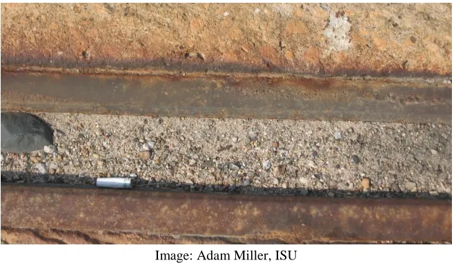
Image: Adam Miller, ISU
Figure 2.7. Badly weathered, but still functioning, strip seal joint
This buildup causes a number of problems. The abrasive nature of the collected materials causes additional wear to the neoprene seals. Additionally, this buildup may prevent the expansion joint from closing properly during warm summer months. The material essentially decreases the allowable expansion distance. This can cause additional stresses to build up in the end of the bridge deck during warm summer months.
Strip seals and compression seals also suffer from spalling of the concrete immediately on either side of the expansion joint. Spalls by themselves are often not severe enough to cause joint failure. They do, however, lead to other problems. Spalls allow water and corrosive chemicals to penetrate more easily to the reinforcing bars at the end of the bridge deck. This may eventually lead to larger spalls and weakened concrete holding the joint in place. Water may also begin to penetrate the interface between the concrete and the joint. Eventually, the back of the joint can begin to rust as can be seen in Figure 2.7 above.
Expansive force due to the formation of pack rust can force the join forward. Additional stresses are then placed on the joint anchorages, which, when coupled with normal traffic loading, can then separate from the extrusion.
Mark Carter had on hand several examples of joints where the extrusion pulled free from the extrusion anchor at the weld that connects the two. This tipping forward of the joints also makes them more susceptible to snowplow damage by creating a small ledge that can be caught by the blade.
Failure of extrusion sections in Iowa by snowplow damage, traffic loading, or otherwise early in the lifespan of the joints are not common and are usually considered to be a result of faulty installation.
Unique to compression seals, sections of the steel armoring may fracture under traffic loading. Failure of the steel armoring is particularly common in the wheel path. After the loose armoring is removed, the concrete below is often revealed to have been inadequately consolidated. The inadequate consolidation results in a series of voids beneath the steel armor causing a significant increase in stress that the steel armoring is not intended to resist. After enough loading cycles, sections of armoring eventually fail, fracture, and come loose. Loss of the steel armoring is generally not a major point of joint failure by itself and can be repaired easily. However, the failure of the steel armor is, in general, a sign that the joint is rapidly approaching the end of its useful life and will likely need a major repair or replacement in the next few years.
2.5.2 Signs of Joint Failure
Failure of a strip seal joint and a compression seal joint is less apparent than it is with a sliding plate joint. The easiest way to tell if a gland has failed is by visually inspecting the gland for tears and punctures. However, failure of the neoprene glands can be difficult to observe visually if the failure is still small. Debris collected in the joint will exacerbate the difficulty of seeing the failure visually.
Joint leakage can also be determined from the effects on the underside of the bridge. Rusted substructure components, debris buildup, and visible moisture, particularly after rain, on the underside of the bridge deck are all signs that the seal may have failed. However, these are general signs of a leaking joint and could very well be other problems aside from a failed gland.
In the case of rust, it can be difficult to see the extent of the damage visually until it has reached a severe level. It can be particularly difficult to tell if a joint has become misaligned due to rust buildup between the joint and the bridge deck.
Rust tends to force the top of the joint forward. When strip seal extrusions are initially
constructed they are set with the top surface parallel on both extrusions. Ideally, the top surface is also parallel to the bridge deck. The same applies to compression seal armoring. Thus, the amount of movement can be roughly estimated from the misalignment of the joint. However, it can be difficult to observe the extent of the joint movement.
Signs of concrete spalls are more difficult to observe before damage becomes visible. Hammer tapping, such as that described in the American Society for Testing and Materials (ASTM) ASTM D 4580, remains one of the best methods for determining the state of concrete
delamination. However, the Iowa DOT Office of Maintenance generally ignores concrete spalls in the joint header until the damage is visible.
Diagrams of joint components can be found previously in Figure 2.5 and Figure 2.6. Note that generally ignoring concrete spalls in the joint header until the damage is visible only applies to Iowa DOT maintenance of joint headers and does not include deck repairs or contracted work. Spalls of small areas such as concrete headers are just not economical to test regularly until the damage shows.
Signs of fatigue for steel expansion joint parts are typical of those for any steel member. Cracks and unintended movement of the steel armoring are the most noticeable signs of fatigue failure.
2.5.3 Joint Maintenance Efforts
There are a variety of maintenance efforts that can be undertaken to correct the previously discussed deterioration. The simplest problem to solve would appear to be the collection of debris in the seal. One solution is to apply compressed air or pressurized water at regular time intervals and remove the debris from the joints.
It is estimated that joints ideally require cleaning twice during the spring and summer months. It is unnecessary during the winter as the joints are generally in a more open position and,
therefore, less likely to have issues with debris blocking expansion movement as the bridges contract. In addition, it is during winter that a lot of the debris, particularly from sand and salts applied to the road during winter weather, accumulates. However, joint cleaning is not
universally performed by the Iowa DOT.
In District 6, specifically, debris is only removed when other work is being completed on or nearby a joint. The given reason for this shortfall in maintenance is a lack of labor because the maintenance offices do not have enough labor to spare man hours for cleaning debris out of expansion joints.
A lot of discussion was present during our investigation on the problem of debris collecting in expansion joints. The literature reviewed during the literature review also commonly discussed this problem. Mark Carter’s suggested solution for this problem was to contract out joint
in-house, to clean out the joint. However, Mark pointed out that a strong wind could blow this contaminated water onto the substructure of the bridge, potentially causing the same damage the joint is intended to prevent. So, while this idea has merit, it is not nearly as simple as suggested and would require some form of drainage system to work properly and protect the substructure.
Broken and failed seals are also rather straight-forward to fix. In most cases, a failed seal can simply be removed, the extrusions cleaned, and a new seal installed. It is allowed by the Iowa DOT to simply remove the failed portion of the neoprene seal and splice in a new section. However, in the Iowa DOT’s experience, it has been found that the repairs last longer if an entirely new seal is installed across the entire joint.
Field splices in the neoprene strip seal are difficult to properly construct and are prone to early failure between the old and new sections. Thus, it is suggested that field splices should be used on the neoprene joints only when absolutely required to replace the seal. Typically in Iowa, neoprene seal replacements are contracted out and not completed by the Iowa DOT.
Spalls are most commonly repaired by removing the loose concrete and patching the spalls with new concrete or asphalt. These repairs can generally be performed quickly with little traffic disruption. Cure time for the concrete patch tends to be the longest part of these jobs. Traffic disruptions for these repairs could be made even shorter with a faster curing, yet still durable concrete mix to use for patching. As well, it was stated that spalls should be repaired as soon as possible after they appear, to prevent further damage of the reinforcement and steel joint components from chloride penetration.
Despite the best efforts to prevent damage to the strip seal extrusions, it is common for them to see severe damage toward the end of their lifespan. Despite the use of corrosion-resistant steel, it is typical for joints to have considerable rust buildup toward the end of their useful life. As the rust buildup is often between the steel extrusion and concrete header, there appears to be little that can be done in terms of maintenance to address this issue. It is likely that a section of the steel extrusion will eventually be torn loose from the rest of the joint.
Loose sections of extrusion are fully repaired only if the damage is done in the early stages of the joint life cycle. If the joint is old, it will likely be programmed for replacement and little more action taken. If the failure is early, repairs will be necessary to avoid further damage to the bridge substructure.
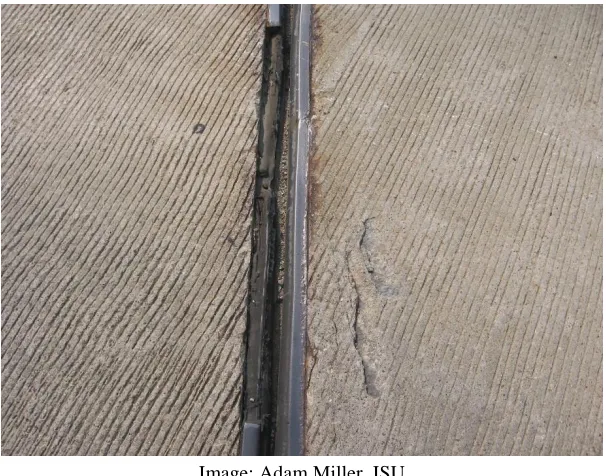
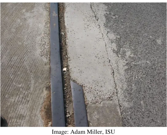
Image: Adam Miller, ISU
Figure 2.8. Strip seal joint with missing extrusion section
The considerable rust between the joint and header concrete leads to the conclusion that this section of extrusion was probably pulled free from the anchors. The forward movement of the joint likely allowed a snowplow blade to catch the extrusion and pull it free. If the joint was still fairly new, concrete may be removed to allow a new section of the extrusion to be embedded and field welded to the existing sections.
Maintenance personnel cautioned that if only a new section of the extrusion, and not an entire new extrusion across the bridge deck, is to be installed, the section should extend from the failed section to the edge of the bridge. In other words, there should only be one point of contact between the old and new sections of joints. It was their experience that a new section of extrusion placed between two existing sections tended to buckle during hot weather. The buckling combined with normal traffic loading often fatigued the field welds quickly on either end, and the welds would soon fail. While the extrusion should still be embedded into the concrete, the broken welds allow water to flow through the joint rendering the repair ineffective. As well, the splice weld should avoid the wheel path of the bridge, even if doing so requires removing a larger section of the broken extrusion than otherwise be necessary.
was then used to both hold the neoprene seal against the concrete and to again create a watertight seal where the extrusion was now missing. This repair had been in place for several years and, with occasional maintenance, this repair was performing at an acceptable level.
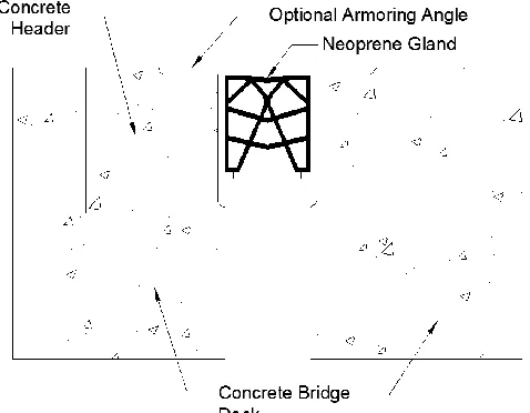
Broken sections of compression seal armoring are fixed much in the same way that sliding plate joints are fixed, by replacing the broken armoring, and any loose concrete, with new concrete to provide a flat, smooth riding surface. In this situation, compression seals have the advantage of still maintaining a well-functioning seal provided the concrete header is still largely in good condition and there is no damage to the neoprene gland. The steel armoring is merely present to protect the concrete edge and increase the durability of the joint. The armoring does not actually contribute to the ability of a joint to be watertight or accommodate expansion and contraction. This type of repair is shown in Figure 2.9
[image:29.612.170.442.256.476.2]Image: Adam Miller, ISU
Figure 2.9. Compression seal joint with failed section of armoring
These repairs tend to be completed in several hours as there is no major removal of concrete involved. The longest schedule element is the required cure time for the new concrete.
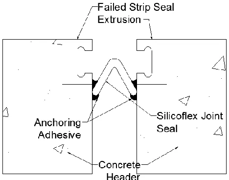
Drawing: Adam Miller, ISU; adapted from R.J. Watson, Inc. (www.rjwatson.com/wp-content/uploads/silicoflex-brochure-may.pdf)
Figure 2.10. Silicoflex expansion joint example
The seal can be attached to any flat vertical face of the joint. This means there is no need for concrete demolition, and no need to remove any existing steel sections of the joint. The new seal can be attached directly with the adhesive below the existing sections of extrusion. Major
concrete damage to the vertical face will still require repair to allow a bonding surface for the Silicoflex joint.
The lack of any major removal, lack of concrete construction, little to no cure time, and the ease of installation makes this a very quick and cheap joint to install. The manufacturer brochure estimates less than 30 minutes for installation per lane, assuming that the only construction task is the joint installation, with the possibility of the bridge opening about an hour after the end of the installation (R.J. Watson).
To date, this joint had been used on at least two repair projects in Iowa, one of which had experienced a major early loss of a large section of the existing strip seal extrusion. As of the writing of this report, the first annual inspection of this joint had not been completed on either of these projects. Durability and functionality information will be included in a later phase report provided that it becomes available.
2.6 Finger Joints and Modular Expansion Joints
Drawing: Adam Miller, ISU; adapted from D.S. Brown Company (dsbrown.com/Resources/Bridges/Steelflex/Joints/D320-PV-S.pdf)
Figure 2.11. Modular expansion joint
Currently, the Iowa DOT tends to favor finger joints for large expansion distances. However, there are still several modular joints installed on bridges in Iowa.
2.6.1 Joint Deterioration
There was much less discussion with Mark Carter about finger and modular joints than about the other joint styles. This is not surprising as there are only 58 bridges in Iowa with finger joints installed compared to almost 400 bridges still utilizing sliding plate joints and more than 500 bridges utilizing strip seal joints. Because there are fewer of these types of joints, it follows that mean less time is spent maintaining those joints and there were, in general, few problems with finger joints to begin with.
Since finger joints are not watertight, debris tends to pass through the joint without causing trouble to the joint. In addition, the nearly continuous riding surface prevents most all damage from snowplows catching raised edges of the joint. In fact, the only real problems that were given for finger joints included spalling of the header concrete, which is a problem that is typical of almost all joint styles, and the rare failure of one of the joint fingers. The structural failure of a finger can generally be traced to heavy traffic loads, especially if average daily traffic has
increased since the initial design and installation of the joint.
Another problem relating to these troughs is the flow of water. Where strip seal, compression seal, and modular joints prevent water from passing through the joint entirely, finger joints merely divert the water after it flows through the joint. Some troughs divert water away from the center of the abutment, while a neoprene trough below a finger expansion joint, as shown in Figure 2.12, diverts water to a catch basin at the center of the footing.
[image:32.612.164.448.156.383.2]Image: Adam Miller, ISU
Figure 2.12. Neoprene trough below finger expansion joint
Image: Adam Miller, ISU
Figure 2.13. Exposed piling from slope erosion
Modular expansion joints show many of the same problems that strip seal joints show. Neoprene glands again begin to fail at about year 15 and, as shown in Figure 2.14, incompressible debris collects in the joint.
Image: Adam Miller, ISU
[image:33.612.145.467.413.667.2]Figure 2.14 shows the problem of debris preventing full closure of the joint particularly well, as it was taken on an extremely warm summer day. Most joints had already been or were nearly completely closed.
Concrete spalls are also quite common in modular joints. It has been found that in almost every case, spalls occur over the location of the support boxes, the steel boxes creating openings in the bridge deck for the support beams to rest, at between 9 and 11 years of age. This is very exact in comparison to most other joint styles that tend to spall at random points along the length of the joint from about 10 years until the joint is replaced.
Figure 2.14 also shows the problem of rust formation inside the steel extrusion, as was first mentioned with strip seal joints in Section 2.5.1 The left seal is not inserted into the center beam in this figure and is thus allowing a small amount of waterflow through the joint. This was explained to not be a common occurrence and that it only occurs on extremely old expansion joints. This particular joint was more than 30 years old and the neoprene seals had been replaced twice. It was found during the last neoprene seal replacement that there was just too much rust in that section of the center beam to fit the neoprene seal in place.
Given that the neoprene is held in place by the compressive action of the steel extrusion, the neoprene seals can already be difficult to install. If that compressive area is reduced even more, it can become impossible to install. Since the joint is already quite old, no major maintenance measures were taken. At this age, the joint needs to be replaced because any maintenance efforts would be ineffective and cause unnecessary traffic interruptions.
There are few visual indications of deterioration for finger joints. Tearing of the neoprene trough is extremely difficult to see as the troughs are often anchored to the bridge deck. Soil erosion problems may be detected by watching for places where the soil has washed away.
2.6.2 Joint Maintenance Efforts
Maintenance efforts for finger joints are rather straightforward. When neoprene troughs break, they are replaced with new troughs. Splices are allowed but, like neoprene glands, splices are not suggested unless absolutely required.
Erosion is addressed by replacing the eroded soil and compacting the new soil as well as possible. Erosion fabric may be placed, but is not done universally. Ideally, rip rap is placed on the eroding slope to help prevent further damage, but this is rarely done due to the expense and time required.
All in all, finger joints tend to require little actual maintenance between installation and replacement. However, finger joints also tend to be more expensive for initial installation and replacement due to the large amount of steel used in the joint.
Modular joints are disliked by many engineers and are not commonly utilized by the Iowa DOT. The first modular joints installed had a tendency for abrupt early failure. The substantial number of modular joint failures eventually led to the commissioning of the National Cooperative Highway Research Program (NCHRP) Report 402 – Fatigue Design of Modular Bridge
Expansion Joints. This study determined the major causes of failure and then outlined solutions to be taken, and notably that welds were often undersized and that fatigue damage was often not considered during design. Since the publication of this report, modular joints have improved considerably and are no longer prone to early failures. In fact, Mark Carter stated that modular joints were his preferred style, as the many components of the joint allowed pieces of the joint to be replaced instead of the entire joint.
Specifically in the maintenance of modular joints, like strip seal joints, torn neoprene glands are replaced. Although splices are allowed, they are still not suggested. Also, spacer springs beneath the joints are replaced regularly. These springs are used to ensure that the separate center beams are spaced evenly during bridge expansion and contraction. Their failure can be seen easily by bulging in the spring or the failure to return to their relaxed condition during the appropriate expansion or contraction.
Support beams are also painted occasionally to help prevent corrosion. It was cautioned that painters need to be extremely careful to keep paint off the sliding surface in the support box as this may prevent proper movement of the support beams. Other damage to modular joints is addressed in the same fashion as a strip seal joint.
2.7 Integral Abutment Joints
Integral abutment joints were examined only briefly in this investigation. Bridge Crew leaders stated that integral abutment joints were their preferred style of expansion joint because they are largely maintenance free. This preference in Iowa largely mirrored a survey of several other states conducted by Chang and Lee (2001) that reached a similar conclusion in the states surveyed.
There were only two main maintenance issues pointed out with regard to integral abutment joints. The first was the occasional patching of the tire buffing and silicon sealant (CF) joint used in Iowa to accommodate the movement between the abutment and the approach slab. The second problem dealt with erosion from the runoff at the end of the bridge.
Erosion comes from the water runoff at the end of the bridge. During rainstorms, water flows over the joint, off the sides of the approach slab, and down around the abutment. Over a period of time, this water can wash away soil surrounding the abutment and eventually expose the pilings, similar to the situation described above pertaining to finger joints.
This erosion problem is known to Iowa DOT staff who are currently working on implementing a new detail for wing armoring on bridges. The detail for new bridges includes a bed of erosion stone atop a layer of engineering fabric atop the compacted subgrade and following the slope of the subgrade. This layer of stone should act as a drain allowing the runoff to quickly flow around the abutment and footing without eroding the supporting soils. A profile view of this new detail is shown in Figure 2.15. Erosion is repaired in the same fashion as it is for finger joints. Eroded soil is replaced, compacted, and monitored for any future problems.
[image:36.612.160.454.262.468.2]Schematic: Iowa DOT
CHAPTER 3. CURRENT JOINT REPLACEMENT PRACTICES
3.1 Chapter Overview
This chapter explains the details involved in two bridge deck expansion joint replacement projects that were observed during this first phase of the project. This chapter is organized by project. Each section provides an overview of information specific to each job and then provides pertinent observations that were made throughout the course of each project.
3.2 Introduction
In construction, challenges exist in communication and understanding between the design engineers and the workers completing the physical repairs in the field. Design changes can help expedite field work, but existing processes to replace expansion joints must be understood before changes can be made. Conversely, many jobsite supervisors may also have ideas that can
facilitate more rapid completion of the repairs, but lack the engineering knowledge required to ensure that a design meets required standards for safety and durability. Thus, an objective of this chapter is to make engineers more intimate with the specific means and methods currently used during joint replacement projects.
3.3 Northbound I-380 Joint A Replacement
Image: © Google 2014
Figure 3.1. Northbound I-380 project location
Image: © Google 2014
Figure 3.2. Approximate locations of expansion joints
In total, five expansion joints were to be replaced as part of this project over three consecutive weekends. Observations of the project were made during the first weekend. Detailed records were only kept for Joint A. However, some comparisons were also made throughout the project involving Joint D.
The initial staging during the first weekend of work entailed replacing both joints on the exit ramp, Joints D and E, as well as half of Joint A. The remaining half of Joint A, as well as Joint B and C, were replaced in sections over the next two weekends. With this staging plan, only the exit ramp would be entirely closed to traffic, and only for a single weekend. This closure could not be avoided due to the width of the ramp. For the remaining two weekends, at least one lane would always remain open.
3.3.1 Joint Condition and Replacement Plan
Joint A was an old sliding plate joint still in use long past its service life. Overall, the joint did not appear to be in extremely bad condition, because only an approximately one-foot long
Joint A Joint D Joint E
section of plate had broken loose. However, when the top steel plate was removed, it revealed a considerable amount of rust that had built up. There was enough rust between the plates of the expansion joint that both the Iowa DOT inspector and the author doubted that the joint had been properly functioning in years. Not surprisingly, this rust buildup conforms to the joint
deterioration patterns discussed previously in section 2.4.1 Other joints in this project, and Joint E in particular, exhibited much more severe failures that ultimately prompted the replacement.
The old sliding plate joint was to be replaced with a new strip seal expansion joint. Concrete removal would consist of the top of the backwall from the existing riding surface to the top of the paving notch and the end two feet of roadway concrete (see Figure 3.3).
[image:40.612.190.432.232.450.2]Schematic: Iowa DOT
Figure 3.3 Typical I-380 concrete removal cross section
Unlike other joint replacements, this job did not require the removal or replacement of the approach slabs, paving notch, or the entirety of the backwall. Embedded rebar was to remain for the reconstruction of the joint. Any bars not embedded in the concrete were to be removed and replaced with epoxy-coated bars, which largely included the existing hoops and longitudinal bars. The new expansion joint and reinforcing steel (rebar) would be formed and constructed using a high early strength concrete mix. Previous tests on the concrete mix had resulted in the development of a maturity curve that indicated the required compressive strength of the concrete of 4,000 psi to be reached in 9 to 12 hours.
3.3.2 Joint A Replacement and Methods
Traffic closures were allowed from 7:00 p.m. Friday evening until 6:00 a.m. Monday morning. Thus, traffic control measures started precisely at 7:00 p.m. Friday evening. Traffic control initially consisted of signage that directed traffic to change lanes, as well as traffic cones to designate closed lanes. The initial use of traffic cones allowed equipment mobilization to proceed as soon as possible after the 7:00 p.m. project start time.
Table 3.1. Construction task length by hour
Date 7/19 7/20 7/21
Activity Hour 7 8 9 10 11 12 1 2 3 4 5 6 7 8 9 10 11 12 1 2 3 4 5 6 7 8 9 10 11 12 1 2 3 4 5 6 7 8 9 10 11 12 1 2 3 4 5 6 7 8 9 10 11 12
Traffic control Equipment
mobilization Hydrodemoli-
tion of Joint A Demolition
with 15-lb chipping
hammers Formwork
and rebar
placement Concrete
placement
Table 3.2. Total construction task lengths
Activity
Total Hours
Traffic Control 4
Equipment Mobilization 2 Hydrodemolition of Joint A 14 Demolition with 15lb Chipping
Hammers 6
Total Demolition Time 20 Formwork and Rebar Placement 13 Concrete Placement and Cure Time 11
3.3.2.1 Joint A Concrete Removal
Equipment mobilization began shortly after traffic was completely rerouted, which was about an hour into the project. This job was unique in that the contractor utilized hydrodemolition for the majority of the concrete removal on Joint A. The contractor utilized an Aqua Cutter from Aquajet Systems AB, similar to the one shown in Figure 3.4.
Image: Iowa DOT
Figure 3.4 Aqua Cutter hydrodemolition machine
[image:43.612.159.454.374.609.2]The aqua jet equipment took several hours to set up and properly align with the limits of demolition before the contractor could begin cutting. While this happened, the steel plates that formed the existing expansion joint were removed with an oxy-acetylene torch. It was explained by the supervisor that the aqua cutter would not be able to remove any concrete below the steel. Thus, the more concrete that could be exposed, the less concrete that would need to be removed by hand.
A moveable cage, which was essentially a few aluminum fence posts with several layers of orange snow fence, was placed around the aqua cutter on three sides. It was explained that during demolition, small particles or broken concrete may be thrown into the air. The particles would be small, ejected with little force, and of no danger to the workers or observers. However, these small particles could potentially cause superficial damage to passing traffic and damage to passing traffic needed to be prevented.
Demolition with the aqua cutter started promptly at 10:30 p.m., but was stopped after a short time. It was discovered that, upon removing the bottom layer of concrete, the water jet was digging a trench in the ground beneath the bridge. This had been anticipated by the contractor as a potential problem and the delay was short while sections of scrap steel plate were placed beneath the sections that were to be removed. The demolition process then continued.
The aqua cutter had a demolition width of about 5 ft. After completing the removal between the required limits, the machine was moved to the side, realigned with the previous sections of demolition, and restarted. Hydrodemolition of Joint A took place for about 14 hours (see Figure 3.5).
[image:44.612.137.475.430.630.2]Image: Adam Miller, ISU
be larger if the joint is at a skew to the curb. There was also a small section of concrete beneath the existing joint that could not be removed with the aqua cutter (see Figure 3.6).
[image:45.612.137.477.113.384.2]Image: Iowa DOT
Figure 3.6 Concrete remaining after hydrodemolition
The remaining concrete was removed with 15-lb chipping hammers. This was much slower than the removal by hydrodemolition, but also consisted of concrete often in confined areas and corners. Removal with chipping hammers was about a 6-hour task, bringing the total time for demolition to 20 hours.
Removal of Joint D had been done with 15-lb chipping hammers until the water jet had finished on Joint A. At this point, about a third of Joint D had been removed with 15-lb chipping
hammers. The water jet was then moved to Joint D to finish removal of that section, while the 15-lb chipping hammers were moved to Joint A to remove the remaining concrete.
3.3.2.2 Joint A Formwork and Reinforcing Placement
The formwork installation started when about half of the existing joint had been entirely
removed. Formwork was not complicated for this project and consisted of plywood supported by 2x4 lumber. Some of the sections had been precut and preassembled to expedite the process of installing the formwork. The concrete profile was identical to the section to be removed (shown in Schematic: Iowa DOT
than 90°. Other shapes, such as the angled profile of many paving notches, are more time consuming to construct than simple rectangular sections. Formwork was all placed by hand as the sections were not large enough to require any additional equipment.
The installation of the new reinforcing bar proceeded shortly after the bottom sections of formwork had been placed and supported. Waiting until the forms are in place allows the reinforcing steel to be supported by the forms at the proper elevation, by the use of rebar chairs, and ensures that proper cover requirements are met the first time the rebar is installed.
On this particular job, the contractor had to install, then remove and reinstall the rebar several times before the layout was correct. Overall, the additional effort involved in installing the rebar probably added several hours to the project length. The Iowa DOT inspector commented that the workers appeared inexperienced with rebar placement.
The reinforcing steel (rebar) was placed and tied together by hand with epoxy-coated rebar tie wire. The expansion joint extrusion was set in place with the reinforcing bar. The joint extrusions were separated by a piece of three-quarter in. foam insulation and then clamped together. The foam insulation would maintain the proper spacing while the concrete was poured and was both compressive and easily removed in pieces if the deck was to undergo expansion before the insulation was removed.
While the reinforcing steel was being placed, the end sections of formwork and bulkheads, again constructed out of plywood and dimensioned lumber, were installed. Formwork and rebar installation finished in the early hours of the morning and no additional work was completed on Joint A until later in the morning when the concrete batch plant opened to provide concrete. At this point, Joint A would easily be finished before the set deadline as long as the concrete was delivered to the site at a reasonable time.
3.3.2.3 Joint A Concrete Placement and Finishing
Concrete placing and finishing was an easy task on this project. Concrete arrived at the site promptly at 10:00 a.m. A high-range water-reducing admixture, as well as other chemicals, were added to the concrete on site immediately before the concrete was placed. The engineer that designed the concrete mix stated that the concrete would begin to set initially about 25 minutes after the chemicals were added, with previous tests showing required strengths being achieved in about nine hours.
Image: Jacob Shaw, ISU
Figure 3.7. Flexible shaft vibratory compactor
Once the concrete was placed and vibrated, the clamps holding the joint extrusions in place were removed. Even though the concrete had not yet set, pressure of the concrete behind the extrusion would hold the joint against the insulation separator.
The concrete was then finished by hand, first with wooden floats and then with magnesium finishing trowels, to provide a nice smooth riding surface. Curing compound was sprayed on the surface of the concrete, and the joint was left to cure.
3.3.2.4 Conclusions and Discussions
Some conclusions were made during the observations of this jobsite. The conclusions were reached during downtimes during discussions between the research team, the Iowa DOT inspector, and the jobsite supervisor.
Demolition was the single longest construction task with concrete cure time taking the second most amount of time
There was no clearly obvious way to precast an expansion joint
The prebuilding of formwork was a particularly prevalent topic. The same contractor had completed an identical job on the southbound lanes of I-380 the summer before and had not pre-manufactured any formwork. To save time during the observed job, general formwork shapes had been pre-constructed before the job began.
The discussion focused on the possible use of a pre-manufactured steel form that could be erected much more quickly. However, this idea was discarded as nearly impossible because, even though the Iowa DOT provides standard profiles for bridge members, the final dimensions often vary slightly. It would take a substantial number of different forms to have a form that would work for almost every bridge. Thus, it was just easier, cheaper, and seemingly slower to use plywood formwork and construct a portion of it during the job.
3.4 US 18 over the Wapsipinicon River
The US 18 over the Wapsipinicon River project (see Figure 3.8) was a typical joint replacement job for the Iowa DOT.
[image:48.612.73.543.319.557.2]Image: © Google 2014
Figure 3.8. US 18 Over Wapsipinicon River project location
3.4.1 Joint Condition and Replacement Plan
When the site visit to US 18 was conducted, the existing sliding plate joints had already been removed from the bridge deck and abutment. However, the removed sliding plate joint sections were still present at the jobsite. The joint sections were badly rusted and had a significant number of broken plate sections. The bridge was originally built, including the old sliding plate joint, in 1978, making the existing joint almost 35 years old. There was not likely any particular circumstance that caused the joint to rust and fail. It was, quite frankly, just old.
This joint was set up as a typical replacement of a sliding plate joint with a new strip seal joint. Also included in the project were the removal and replacement of the paving notch, a portion of the abutment, and the doubly reinforced approach slab on both ends of the bridge.
Concrete removal was to consist of a 1-ft by 1-ft square section of concrete on the deck side of the joint along with the removal of the backwall to 1 ft 9in. below the bottom of the existing paving notch (see Figure 3.9).
[image:49.612.210.403.326.534.2]Schematic: Iowa DOT
Figure 3.9. Typical US 18 removal cross section
Schematic: Iowa DOT
Figure 3.10. Replacement paving notch plan
The US 18 job was given a contract length of 75 work days for completion. The job was constructed in three stages to provide one open lane of traffic at all times during the project.
Stage 1 consisted of the closure of the westbound lane and the construction of a paved asphalt shoulder on the westbound lane of the approaches. This paved shoulder effectively widened the westbound lane and allowed traffic to be routed partially onto the shoulder of the bridge, allowing a wider construction zone in the eastbound lane.
Stage 2 consisted of the reconstruction of the eastbound lane expansion joints, approaches, and the paving of the shoulder. During Stage 2, one lane of traffic was maintained on the westbound lane.
Stage 3 consisted of the reconstruction of the expansion joints and approaches on the westbound lane.
joint at the eastern abutment had been replaced. The second half of the eastern abutment was in the process of being demolished.
It had been noted during the I-380 observation that demolition seems to be the driving factor in how long a project takes. Thus, US 18 was observed during the demolition phase. The inspector noted that on the previous three sections, demolition had taken about three total days. After demolition, half of a day was usually required to straighten the vertical reinforcing bars that would remain embedded in the rebar.
It was observed that the existing horizontal bars on the deck side of the joint took little damage and could be efficiently removed with 15 lb chipping hammers. The backwall and paving notch had mass removal completed with a skid loader mounted hydraulic breaker. 15 lb chipping hammers were utilized to remove the final sections of the backwall to provide a relatively straight, smooth edge for reconstruction. Such detailed removal was not possible with a hydraulic breaker. Removal with the hydraulic breaker caused some small damage to the embedded reinforcing bar. However, this damage, mainly the bending of bars, was small and could easily be corrected after demolition.
As previously discussed, the biggest hindrance to faster demolition is the requirement that the existing vertical reinforcing bars in the backwall typically must remain in place to develop lap splices. Demolition would proceed faster with larger demolition equipment. However, larger hydraulic breakers would cause an unacceptable level of damage to the embedded reinforcing bar. If these reinforcing bars could be removed, the rate of demolition could be increased. The alternative to maintaining the embedded bars is to drill holes and epoxy new reinforcing bars into the existing footing. On some projects this would be an additional construction task and more equipment. However, on this and many projects the new abutment design required the addition of a third row of vertical reinforcing between the two existing rows. These bars can be seen in Schematic: Iowa DOT
Figure 3.10 above labeled as bar 5b2. In similar designs, there would be no additional step in the construction process, merely a step that would be lengthened while another is made shorter.