Please cite this article as: A. Wagih, Experimental and Finite Element Simulation of Nano-indentation on Metal Matrix Composites: Hardness Prediction, International Journal of Engineering (IJE), TRANSACTIONS A: Basics..Vol. 29, No. 1, (January 2016) 78-86
International Journal of Engineering
J o u r n a l H o m e p a g e : w w w . i j e . i rExperimental and Finite Element
Simulation of Nano-indentation on Metal Matrix
Composites: Hardness Prediction
A. Wagih
Mechanical Design and Production Department, Faculty of Engineering, Zagazig University, Zagazig, Sharkia, Egypt
P A P E R I N F O
Paper history:
Received 23 February 2015
Accepted in revised form 24 December 2015
Keywords: Nanocomposite Mechanical Milling Finite Element Simulation Hardness
A B S T R A C T
The scientific importance of nanocomposites is being increased due to their improved properties. This paper is divided into two parts. First, Al-Al2O3 nanocomposite was produced by using ball milling
technique followed by cold compaction and sintering. Microstructure and morphology studies were done through SEM, TEM, and EDX analyses on the produced powder. The mechanical properties of the produced composite were determined by the tensile test. Also, nano-indentation experiment was conducted on the produced composite to determine its hardness. Second, a 2-D axisymmetry model was implemented in ANSYS software to simulate the nano-indentation experiment on pure aluminum and Al-Al2O3 nanocomposite. A conical indenter with 70.3◦ was considered in simulations. The results
show that, a homogenous distribution of the reinforcement in the matrix was achieved after 20 h milling. The elastic modulus, yield strength, and the hardness of the produced composite were increased compared to the pure metal. The finite element (FE) simulation results showed a good agreement with the experimental results for nano-indentation experiment. The scatter of the FE results from the experimental results in the pure metal was smaller than that observed for the nanocomposite.
doi: 10.5829/idosi.ije.2016.29.01a.11
1. INTRODUCTION1
Metal matrix composites (MMC) are manufactured using different techniques. These techniques could be classified as: solid state processes, liquid-phase (casting) processes, and liquid-solid processing. The limitations of the second and the third techniques arise from difficulties in mixing the two phases thoroughly, difficult determination of critical temperature for infiltration, problems due to fluidity and /or wettability at m a t r i x - reinforcement interface. Powder metallurgy (P/M) techniques are regarded as one of the solid state
processes and are used extensively in
manufacturing particulate MMC. Using these techniques, t h e matrix a s well as the reinforcement is used in the form of powder. The powders are
*Corresponding Author’s Email: eng_awa2011@yahoo.com, (A. Wagih)
thoroughly mixed in the solid state; then they are manufactured into billets using vacuum hot pressing or degassing followed by hot pressing and hot extrusion. The most important advantage o f this method over the other available method is the control of the mixture homogeneity [1-6].
Of all metals, aluminum and its alloys are considered as one of the most used metals in different applications due to potential light weight and high performance at elevated temperature. Currently, aluminum and aluminum alloys are reinforced by hard particles such as SiC, Al2O3, Y2O3, TiO2 and other reinforcing particles. Particle reinforced aluminum matrix composites possess high-specific elastic modulus, high-specific strength, good wear resistance and excellent properties at elevated temperature over conventional aluminum alloys [7, 8].
composites and compare it with the properties of the conventional materials. Different mechanical test methods are available to measure the mechanical properties of materials. Uniaxial tensile test is a conventional method for measuring the mechanical properties like Young’s modulus, yield strength, strain hardening, toughness and tensile strength. Conventional mechanical test methods are often destructive and need relatively large amount of sample materials. Recently, some researchers started to use the nano-indentation technique to characterize not only the bulk materials but also the thin coatings [9-11]. The advantage of using nano-indentation to characterize the new materials is that this test needs less sample material, decreases costs and is independent of the specimen geometry.
In the last two decades, the use of finite element methods (FEM) for modeling different engineering problems really increased. Indentation process was investigated with FEM by many researchers, to investigate the stress and strain fields under the indenter tip which are used to determine the basic mechanical properties of materials [12-14]. Regarding an appropriate value for the dimension of specimen, as an economic factor in both experimental and numerical simulation. Also, regarding the size effect of the specimens on the precision of the results, finite element modeling can also be used for simulating the nano-indentation process. Some researchers have compared the results obtained from the FE simulation of nano-indentation and the experiment to validate finite element modeling of the nano-indentation process [15-18]. They have shown that the finite element simulation could be an appropriate method for determination of bulk material hardness.
In this paper, a finite element simulation of nano-indentation experiment on nano alumina particle reinforced aluminum matrix was introduced by ANSYS software. P/M technology was used to produce the Al-Al2O3 nano composite. Uniaxial tensile test was used to characterize the produced samples. Also, nano-indentation test was performed to compare the results of simulation with the experimental results to check the validity of the proposed model.
2. MATERIALS AND EXPERIMENTAL PROCEDURE
2. 1. Materials and Processing
Commercial
pure aluminum powder with an average particle size of 80 µm and 99.5% purity and Al2O3 (99.5% purity 80 µm size) were used as raw materials for composite
fabrication. Pure powders were milled to form Al-2.5 wt% Al2O3 composite in a Fritsch planetary ball mill, while confined in sealed 250 ml steel containers rotated at 250 rpm for 20 h.
The container was loaded with a blend of balls (φ = 10, and 20 mm). The total weight of the powder was about 25 g and the ball to powder mass ratio was about 20:1. Stearic acid (3 wt.%) was used as the process control agent to prevent excessive cold welding of powder particles. The milled powders were consolidated by cold uniaxial pressing in a cylindrical rigid die (double action type) at 600 MPa, with zinc stearate (Zn(C18H35O2)2) as a lubricant. The consolidated specimens were cylinders with dimensions of 30 mm and 40 mm in diameter and height, respectively.
The consolidated specimens were sintered in a hydrogen atmosphere at 500 ◦C for 5 h. Sintering was performed in a laboratory electro resistance tube furnace with maximum power of 3 kW and thermoregulation of 1 ◦C. The heating and cooling rates were 10 ◦C/min and 2 ◦C/min, respectively. In order to meet the tensile test requirements, extrusion process was applied to the sintered specimens with 2.25 reduction ratio to reduce the diameter of the specimens to that suggested by ASTM E8/E8M-11 [19].
The powders produced after milling were investigated by SEM Model Quanta 250 FEG (Field Emission Gun) equipped with EDX unit (Energy Dispersive X-ray Analyses), with accelerating voltage of 30 kV. The nanocrystalline nature of the high- energy ball-milled powders was confirmed using a JEOL 3010 high-resolution trans- mission electron microscope (HR-TEM).
2. 2. Uniaxial Tensile Test To investigate the mechanical behavior of the composites, the tensile test was conducted on MTS universal testing machine with a maximum load capacity of 100 kN according to ASTM E8/E8M-11 [ 1 9 ] . The crosshead speed was set at 2 mm/min on the round specimens. Three specimens were tested for each category to check the repeatability of the test.
and then polished by diamond paste. After polishing, to ensure the cleanness of the surface, it is mandatory to use enchant to clean the surface from oxides. 20 indentations for each material were done to ensure the repeatability of the test.
3. FINITE ELEMENT SIMULATION
For time efficiency and simplicity, two-dimensional axisymmetric contact problems were considered. The finite element model is generated using ANSYS commercial software. A conical rigid indenter with half-angle of 70.3 was used in the axisymmetric model which had the same projected area to depth function as the standard Berkovich indenter. Based on the literature, Lichinchi [17] has reported that the sharpness of the indenter has great effect on the response in nano-indentation experiment. So, the indenter was simulated as conical indenter with cone tip having a rounding of R=150 nm. The indenter and specimen were meshed by 2D structural PLANE182. Axisymmetry conditions were applied along the center line. A reasonable fine mesh was required to ensure convergence; a graded mesh was created, where the region in the contact with the indenter was more finely meshed to study the stress distribution under the indenter (see Figure 1). The interaction of the indenter and the specimen was modeled as a contact pair with no friction. Contact element TARGET169 was applied to the indenter and CONTACT175 to the specimen. Non-linear analysis was conducted in this model. Displacement control technique was used to apply the displacement to the indenter in y-direction. Convergence study of FE results was conducted to ensure that the mesh refinement in the composite laminate is sufficiently fine enough to capture the stresses and deformations with reasonably accuracy. The boundary condition was modeled as a fixed support at the lower surface of the specimen to prevent the movements of the lower nodes of the modeled sample, and fixing the horizontal movements along x-axis to meet the x-axisymmetry condition.
The mechanical properties obtained from the uniaxial test were used in finite element simulation of the nano-indentation test. Both loading and unloading steps of nano-indentation process were simulated in the finite element model. The indenter was driven into the specimen surface in the axial direction for 250 nm in 5 s and with a constant speed. When the indenter tip reached 250 nm, the test specimen was un- loaded and the indenter tip returned to its initial position with the same speed as that of the loading stage. In this way, the un-loading part of the load-displacement curve was obtained from the finite element simulation.
Figure 1. Meshing pattern for the specimen used for nano-indentation finite element model.
All calculations were carried out using the axisymmetric cylindrical domain characterized by a radius L=100 µm and height of 50 µm and representing the specimen. The material model used in the present work was elastoplastic model with kinematic hardening and von Mises yield surface. The material response is assumed to be isotropic elastoplastic with exponential hardening following a law, known as Hollomon’s power hardening law obeying von Mises plastic criterion.
4. RESULTS AND DISCUSSION
4. 1. Morphology and Particle Distribution
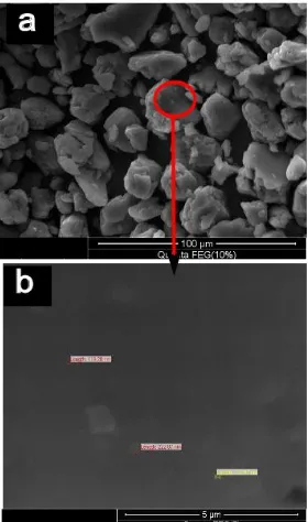
Figure 1 shows the SEM micrographs taken from the as received Al and Al2O3 powders to ensure the particle size of the used powders. Figure 2 shows the SEM micrograph of Al-2.5 wt% Al2O3 powder samples after 20 h milling. The presence of alumina particles causes more work hardening during ball milling [6, 20-22]. As a result, more refinement of aluminum and alumina particles occurred during ball milling. Figure 3b shows a high magnification for specific part from Figure 3c, the small particles of alumina seem to be distributed in uniform manner. Also, the particle size of the alumina particles reaches the nano scale. Figure 4 shows the TEM micrograph of the Al-2.5 wt% Al2O3 after 20 h milling. This Figure gives evidence on the particle size of the reinforcement.
4. 2. Young’s Modulus and Yield Strength The
by adding the reinforcement particles. Young’s modulus can be calculated from the slope of the elastic part of the curve, and the yield strength is the stress at the end of the elastic part. The values of young’s modulus and yield strength were calculated as previously explained and shown in Table 1.
Figure 2. SEM micrograph of samples (a) as received Al powder and (b) as received Al2O3 powder.
Figure 3. SEM micrograph of samples (a) Al-2.5 wt% Al2O3
after 20 h milling and (d) high magnification of Al-2.5 wt% Al2O3 .
Figure 4. TEM micrograph of Al-2.5 wt% Al2O3 after 20 h
milling (a) bright field image (BFI), and (b) dark field image (DFI).
Figure 5. Stress-strain curves obtained form the uniaxial tensile test of Al and Al-2.5 wt% Al2O3.
TABLE 1. The values of Young’s modulus and yield strength.
Material Young modulus
(E, GPa)
Yield stress (σy , MPa)
Pure Al 69.12± 0.42 84.73±1.54
AL-2.5wt%Al2O3 75.4±0.95 92.5±1.82
experimental test for both materials (Pure Al, and Al-2.5 wt% Al2O3). The displacement was regarded as the displacement of point which represents the displacement of the indenter tip.
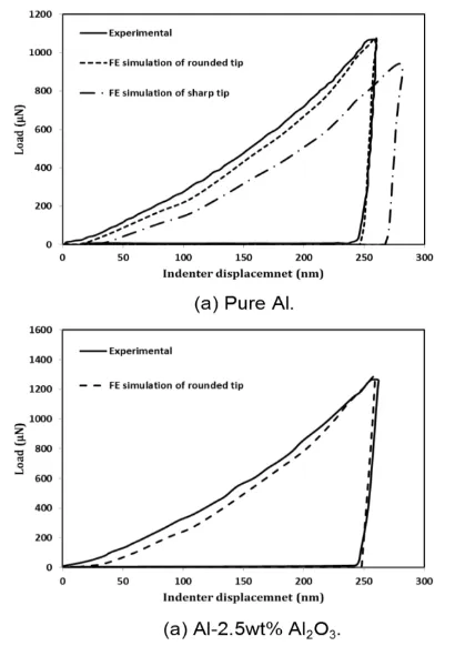
In Figure 6 (a) a comparison between the presented models prediction and the experimental results for pure aluminum metal is introduced. The figure shows good agreement between the FE simulations with a rounded tip indenter and the experiment. However, the agreement between the FE simulations with the sharp indenter tip and the experimental results was so bad. So, a slight curvature of 150 nm was considered for all simulations. As a possible reason for this fact that the indenter used for experiment not perfectly sharp it has small curvature based on the ISO 14577 standard. Figure 6(b) shows a comparison between the FE simulation and experimental results for Al-2.5 wt% Al2O3 nano- composite. The FE simulation achieves a good agreement with the experimental results. The agreement between the FE simulations for pure Al with its experiment is much better than that obtained in the FE simulation for Al-2.5 wt% Al2O3 nano composite. That’s because the experimental load indentation curve is the average of 20 indentations; some indentations are larger and others are smaller in its response. So, the average of the 20 indentations is plotted in Figure 6.
The von Misses stress contour and deformations arund the the indenter tip of pure Al, and Al-2.5 wt% Al2O3 nano composite obtained from the FE simulations is shown in Figures 7 and 8. The von Misses yield criteria assumes that the plastic deformation occurs when the equivalent stress reaches to the yield strength of the material. The equivalent stress can be calculated from:
√( ) ( ) ( ) (1)
where , , and are the three principle stresses generating at each node in the sample during the FE simulation of the nano-indentation test.
Figures 7 and 8 show the von Misses equivalent stresses during loading and unloading for nano-indentation experiment for Al and Al-Al2O3 nano-composite, respectively. Figure 7(a) and 8(a) show the von Misses equivalent stresses at the beginning of the indentation test simulation. The maximum stress under the indenter tip is 82.5, and 94.5 MPa for Al, and Al-2.5 wt. % Al2O3 nanocomposite, respectively, which is in fact greater than the yield strength of the composite as observed from the tensile test (see Table 1). Therefore, the plastic deformations occur around the indenter tip at the moment of contact between the indenter and the sample. As the indentation depth
increased, the plastic deformation zone increased in both directions (longitudinal and through the thickness) until reaching the maximum indentation depth. During the unloading stage the elastic deformations decreased gradually to zero and the residual plastic deformations caused the indentation footprint.
Figure 6. Load-indentation curve obtained from FE simulations and nano-indentation experiment.
4. 4. Hardness Evaluation Before measuring
any phenomena (expressing it in numbers), it is mandatory to know the physical meaning of it. The physical meaning of hardness can be defined as the resistance of material to deformation, indentation, or penetration by means such as abrasion, drilling, impact, scratching, and wear. All previous tests make a footprint into the surface of the specimen (it varies depending on the test and the applied load).
The applied force and the size of the footprint are always used to calculate the hardness value. One of the most important methods for calculating the hardness is presented by Fischer [21].
In Fischer approach, he used a quite general formula for calculating the hardness:
where Fmax is the maximum load and A is the projected area of the contact surface between the sample and the indenter. Fischer introduces an approximate value for the projected area in the nano indentation test with Berkovich indenter depending on the contact depth:
(3)
where hc is the contact depth as shown in Figure 9. Based on the figure, hc can be calculated as:
(4)
where hmax is the maximum indentation depth and ha can be defined as:
( ) (5)
where he is the elastic displacement during unloading stage which can be obtained from:
(6)
Substituting Equations (6) and (5) in (4) the final formula of hc can be computed as:
( )
(7)
After introducing the equations used to calculate the hardness, the most important step is determining the parameters used in this equation from the FE simulation. hmax was obtained from the FE simulation as the displacement of point A in Figure 9 at the end of loading stage. hr also was obtained from the FE simulation as the displacement at point A after the unloading stage (shown in Figure 9 as point B). The computed parameters and the calculated hardness are shown in Table 2.
Table 2 introduce the different parameters obtained form the FE simulations used to calculate the hardness by Equation (2) [21]. By comparing the hardness values obtained by experiment and the results from the FE model, we can conclude that there are only small differences between the experimental result and the FE results for both materials. Therefore, FE simulation could be a successful method to determine the hardness not only for bulk materials but also, for metal matrix nano-composites (MMNCs).
Figure 7. Von Misses stress contours and deformation of pure Al obtained from the FE simulations.
.
TABLE 2. Computed parameters from FE simulation and calculated hardness from FE simulation and experiments.
Material Fmax (µN) hmax (nm) hr (nm) hc (nm) A (nm2) HFE (GPa) Hexp (GPa)
Pure Al 1031.4 250 246.8 248.8 1517260 0.679 0.651±0.105
Figure 8. Von Misses stress contours and deformation of Al-2.5 wt% Al2O3 nano composite obtained
Figure 9. Schematic diagram of nano-indentation test [21].
5. CONCLUSIONS
High energy ball milling technique followed by cold compaction and sintering was used to produce Al-Al2O3 nanocomposite with homogenous distribution of the reinforcement in the matrix. Tensile test and
nano-indentation test were used to characterize the mechanical properties and the hardness of the produced nanocomposite, respectively. Also, a 2-D axisymmetry model was implemented in ANSYS software to simulate the nano-indentation experiment for the pure Al, and Al-Al2O3 nanocomposite. Based on SEM and TEM inspections of the milled powder, the particles had spherical shape and the reinforcement was in homogenies distribution in the matrix. Based on the load-displacement curve obtained from the nano-indentation experiment and the FE simulations, the hardness of the pure aluminum and Al-Al2O3 nanocomposite was calculated. The difference between the results obtained from the experiments and the FE simulation was very small for both materials. Also, the difference between the results form the FE simulations obtained by indenter with sharp tip and rounded tip was compared. The indenter with rounded tip is recommended for the simulation of this experiment. Finally, finite element method is a powerful device to simulate the indentation process at the nanoscale not only in bulk materials but also in MMNCs.
6. REFERENCES
1. Ibrahim, I., Mohamed, F. and Lavernia, E., "Particulate reinforced metal matrix composites—a review", Journal of
Materials Science, Vol. 26, No. 5, (1991), 1137-1156.
2. Klier, E.M., Mortensen, A., Cornie, J. and Flemings, M., "Fabrication of cast particle-reinforced metals via pressure infiltration", Journal of Materials Science, Vol. 26, No. 9, (1991), 2519-2526.
3. Yang, J. and Chung, D., "Casting particulate and fibrous metal-matrix composites by vacuum infiltration of a liquid metal under an inert gas pressure", Journal of Materials Science Vol. 24, No. 10, (1989), 3605-3612.
4. Liu, Y., Lim, S., Lu, L. and Lai, M., "Recent development in the fabrication of metal matrix-particulate composites using powder metallurgy techniques", Journal of Materials Science Vol. 29, No. 8, (1994), 1999-2007.
5. Mazen, A. and Ahmed, A., "Mechanical behavior of al-al2o3 mmc manufactured by pm techniques part i—scheme i processing parameters", Journal of Materials Engineering and
Performance, Vol. 7, No. 3, (1998), 393-401.
6. Wagih, A., "Mechanical properties of al–mg/al 2 o 3 nanocomposite powder produced by mechanical alloying",
Advanced Powder Technology, Vol. 26, No. 1, (2015),
253-258.
7. Hosseingholi, M., Hosseinnia, A. and Pazouki, M., "Room temperature synthesis of n-doped urchin-like rutile tio2 nanostructure with enhanced photocatalytic activity under sunlight".
8. M, K. and H., S., " Zinc adsorption properties of alginate-sbs-15 nanocomposite.", International Journal of Engeneering, Vol. 28, No. 10 (2015), 1415-1422.
9. Ayatollahi, M.R., Doagou‐Rad, S. and Shadlou, S., "Nano‐ /microscale investigation of tribological and mechanical properties of epoxy/mwnt nanocomposites", Macromolecular
10. Karimzadeh, A. and Ayatollahi, M., "Investigation of mechanical and tribological properties of bone cement by nano-indentation and nano-scratch experiments", Polymer Testing, Vol. 31, No. 6, (2012), 828-833.
11. Boroumandnia, A., Kasaeian, A., Nikfarjam, A. and Mohammadpour, R., "Effect of tio2 nanofiber density on organic-inorganic based hybrid solar cells", International
Journal of Engineering, 1025-2495.
12. Sun, Y., Bell, T. and Zheng, S., "Finite element analysis of the critical ratio of coating thickness to indentation depth for coating property measurements by nanoindentation", Thin solid films, Vol. 258, No. 1, (1995), 198-204.
13. Bolshakov, A., Oliver, W. and Pharr, G., "Influences of stress on the measurement of mechanical properties using nanoindentation: Part ii. Finite element simulations", Journal of
Materials Research, Vol. 11, No. 03, (1996), 760-768.
14. Moy, C., Bocciarelli, M., Ringer, S. and Ranzi, G., "Indentation and imprint mapping for the identification of material properties in multi-layered systems", Computational Materials Science, Vol. 50, No. 5, (2011), 1681-1691.
15. Stauss, S., Schwaller, P., Bucaille, J.-L., Rabe, R., Rohr, L., Michler, J. and Blank, E., "Determining the stress–strain behaviour of small devices by nanoindentation in combination with inverse methods", Microelectronic Engineering, Vol. 67, No., (2003), 818-825.
16. Zhang, J., Niebur, G.L. and Ovaert, T.C., "Mechanical property determination of bone through nano-and micro-indentation testing and finite element simulation", Journal of
Biomechanics, Vol. 41, No. 2, (2008), 267-275.
17. Lichinchi, M., Lenardi, C., Haupt, J. and Vitali, R., "Simulation of berkovich nanoindentation experiments on thin films using finite element method", Thin Solid Films, Vol. 333, No. 1, (1999), 278-286.
18. Karimzadeh, A., Ayatollahi, M. and Alizadeh, M., "Finite element simulation of nano-indentation experiment on aluminum 1100", Computational Materials Science, Vol. 81, (2014), 595-600.
19. Testing, A.S.f. and Materials, "Astm designation e 8-00 standard test methods for tension testing of metallic materials, ASTM. (2000).
21. Fischer-Cripps, A.C., Contact mechanics, in Nanoindentation. Springer (2011),. 1-19.
22. Wagih, A., "Synthesis of nanocrystalline al2o3 reinforced al nanocomposites by high-energy mechanical alloying: Microstructural evolution and mechanical properties",
Transactions of the Indian Institute of Metals, (2015), 1-7.
Experimental and Finite Element
Simulation of Nano-indentation on Metal Matrix
Composites: Hardness Prediction
A. Wagih
Mechanical Design and Production Deptartment, Faculty of Engineering, Zagazig University, P.O., Zagazig, Sharkia, Egypt
P A P E R I N F O
Paper history:
Received 23 February 2015
Accepted in revised form 24 December 2015
Keywords: Nanocomposite Mechanical Milling Finite Element Simulation
Hardness
هديكچ
هدش میسقت تمسق ود هب هلاقم نیا .تسا شیازفا لاح رد اهنآ هتفای دوبهب صاوخ لیلد هب اهتیزوپماکونان یملع تیمها
تیزوپماکونان ،لوا .تسا
Al2O3
Al
.دش دیلوت نتخادگ و درس مکارت سپس و یا هلولگ بایسآ شور زا هدافتسا اب
زیلانآ قیرط زا یژولوفروم و راتخاسزیر هعلاطم
SEM
،
TEM
و
EDX
یکیناکم صاوخ .دش ماجنا هدش دیلوت ردوپ
یارب هدش دیلوت تیزوپماک یور یگتفرورف ونان شیامزآ ،نینچمه .دش نییعت یششک تست طسوت هدش دیلوت تیزوپماک
رازفا مرن رد یدعبود نراقتم لدم کی ،مود .دش ماجنا نآ یتخس نییعت
ANSYS
رب هنادند ونان شیامزآ یزاس هیبش یارب
ور تیزوپماکونان و صلاخ موینیمولآ ی
Al- Al2O3
یطورخم هوگ کی .دش ارجا
◦
3.07 رد .دش هتفرگ رظن رد یزاس هیبش
ا سپ سیرتام رد تخوس زا ینگمه عیزوت هک دهد یم ناشن جیاتن
s
ز 0. ،کیتسلاا لودم .دمآ تسد هب بایسآ تعاس
زلف اب هسیاقم رد هدش دیلوت تیزوپماک یتخس و میلست ماکحتسا قفاوت دودحم ناملا یزاس هیبش جیاتن .تفای شیازفا صلاخ
رتمک صلاخ زلف رد یبرجت جیاتن زا دودحم ناملا جیاتن یگدنکارپ .داد ناشن هنادند ونان شیامزآ یارب یبرجت جیاتن اب یبوخ
.دش هدهاشم تیزوپماکونان یارب هک دوب یرادقم زا
doi: 10.5829/idosi.ije.2016.29.01a.11
20. Wagih, A., "Effect of milling time on morphology and microstructure of Al-Mg/Al2O3 nanocomposite powder


![Figure 9. Schematic diagram of nano-indentation test [21].](https://thumb-us.123doks.com/thumbv2/123dok_us/221227.2016639/7.595.73.264.108.454/figure-schematic-diagram-nano-indentation-test.webp)
