Iranian Journal of Electrical & Electronic Engineering, Vol. 1 ,No. 2, April 2005. 81
Analysis of converter-permanent magnet synchronous
machine set by improved average-value modeling
A.Vahedi and M.Ramezani
Abstract: Dc excitation of the field winding in a synchronous machine can be provided by permanent magnets. Permanent magnet synchronous machine (PMSM) can offer simpler construction, lower weight and size for the same performance, with reduced losses and higher efficiency. Thanks to the mentioned advantages these motors are widely used in different application, therefore analysis and modeling of them, is very important. In this paper a new, fast and simple method is presented to study performance of a PMSM connected to the converter. For this purpose, average-value modeling and related analytical relations which leads to the desired characteristics such as electromagnetic torque, dc current and dc voltage is presented and applied to PMSM & converter system. The advantage of this model lie in reduction of computation time compares to the other dynamic models while keeping accuracy quite acceptable. This model is applicable for studying the steady-state performance of systems as well as dynamic performance.
Keywords: average-value modeling, permanent magnet synchronous machine (PMSM), converter, commutation
1 Introduction
Permanent magnet synchronous motors are widely1
used in high performance motion control system because of their desirable features as compared to other motors. In these motors field coils are replaced by permanent magnet, thus it eliminates losses due to field windings. Also frequent maintenance associated with slip rings & brushes is eliminated. PMSM can offer significant higher advantages and efficiency over other types of motors when employed in adjustable speed drives [1]. These motors have high torque to weight ratio, higher efficiency, good power factor, faster response etc. Because of these benefits and the improvements in the properties of permanent magnet materials in recent years, there is wide attention for application of PMSM in industry [2]. Because of wide variety use of theses machines in applications such as submarines, aircrafts, variable speed drives and excitation systems of generators, their modeling and parameter identification, considering the converter connected to them is become interesting for electrical engineering research community [3,4]. The classic model of this system is consisting of 3-phase balanced voltage sources connected to the constant series reactance. Although this model provides the static voltage & current waveforms in short computation time, but the results have not the adequate accuracy [5]. Another modeling approach is the dynamic model (detailed model) that is based on park's model. Although
Iranian Journal of Electrical & Electronic Engineering, 2005.
Paper first received 8th October 2004 and in revised from 10th July 2005.
A.Vahedi and M.Ramezani are with the Department of Electrical Engineering Iran University of Science and Technology, Narmak, Tehran 16844, Iran
this model can offer advantages such as accuracy and ability to construct instantaneous waveform, but the consumed time for calculations is very long [6,7,8]. Rotor & stator's large time constants in addition to calculation’s iteration in each time sequence of switching have a significant effect on this problem. Considering mentioned problems, the average-value modeling is presented to improve the defects of the previous models, i.e. keeping the same accuracy, the computation time is reduced. Next we introduce average value model for an excited synchronous machine, and then extend this model for PMSM.
2 Average-value modeling of excited SM
Consider an excited SM and converter set as shown in Fig.1. In This scheme SM is modeled by non-idealized voltage supplies accompanied by a variable commutation reactance [9].
Fig.1.Representation of synchronous machine & converter system
According to Fig.1, to calculate dc voltage in a switching time zone, for instance in third time zone that starts from beginning of conductance of thyristor No.3 to
Iranian Journal of Electrical & Electronic Engineering, Vol. 2, August 2005. 82
the beginning conductance of thyristor No.4, it can be written:
(
)
ò
++-=
p bb p
q
p
3 2 33
r cs bsdc
v
v
d
v
(1)where angle
q
r is rotor mechanical position andv
bs, asv
are voltages of phase b and c respectively. Substituting voltages byv
bs=
p
l
bs andv
cs=
p
l
cs, equation (1) can be rewritten as:[
]
b p q b p ql
l
pw
w
+ = + =-ú
û
ù
ê
ë
é
=
3 3 23
r r cs bs b r dcv
(2)where
l
cs,l
bs are phase b & c winding’s flux respectively and b is firing angle defined in terms of rotor mechanical position. Applying boundary conditions, 3-phase currents are defined as follows:ú
ú
ú
û
ù
ê
ê
ê
ë
é-=
+ = dc dc abcsI
I
i
r p3b
0
q (3)
ú
ú
ú
û
ù
ê
ê
ê
ë
é
-=
+ = dc dc abcsI
I
i
r0
3 2 b pq (4)
Using analytical equations for mentioned zone and extending it for the other zone, system variables in every desired instant can be accessible. Hence, converter output average voltage can be obtained as:
(
q d) (
d q)
dcb r dc I X X X X E V ú û ù ê ë é ÷ ø ö ç è æ + ¢¢ -¢¢ + ¢¢ + ¢¢ ÷÷ ø ö çç è æ ÷ ø ö ç è æ -= 6 2 sin . 2 1 . . 3 cos 3 3 p b w w p p a (5)
It can be seen that commutation reactance in this model, have not constant value and it’s value changes regarding firing angels as shown in Fig.2.
To calculate average values of q and d-axis’ currents as well as synchronous machine’s electromagnetic torque, current should be already calculated. Note that commutation zone is the period in which two phases are short circuit, for instance, in the third switching zone, we have:
0
=
-=
-
bs as bsas
v
p
p
v
y
y
(6)where
y
=
w
rl
.Fig.2.Commutaion reactance variations versus
b
Using boundary conditions in this zone according to (5) and (6);
y
as ,y
bsare determined in terms ofi
dc,i
as. Now applyingy
as-
y
bs=
K
to the equation (6), the commutation current in third switching zone is derived as follows:(
)
(
)
(
)
(
)
(
q d)
r(
q d)
dc d q r q d d q r d q r d r q as X X X X I X X X X X X X X K i ¢¢ + ¢¢ + ÷ ø ö ç è æ + ¢¢ -¢¢ ú û ù ê ë
é + ¢¢+ ¢¢
÷ ø ö ç è æ -¢¢ -¢¢ -¢¢ + ¢¢ + ÷ ø ö ç è æ + ¢¢ -¢¢ ú û ù ê ë é ÷ ø ö ç è æ + ¢¢ + ÷ ø ö ç è æ + ¢¢ -= 3 2 cos 2 1 3 2 cos 3 2 cos 6 sin 6 cos 3 p q p q p q p q y p q y (7) where
(
)
(
d q)
(
q d)
dcd q I X X X X K ú û ù ê ë é ¢¢ + ¢¢ -÷ ø ö ç è æ + ¢¢ -¢¢ + ¢¢ + ¢¢ = 2 1 3 2 2 cos cos sin 3 p b b y b y (8)
now according to the average values of currents in the third switching zone that are defined as follows:
( )
( )
q p b q p bq + + £ £ + ú ú ú û ù ê ê ê ë é -= 3 3 u I i I i i r dc r as dc r as
abcs (9)
b p q b
p + + £ £ +
ú ú ú û ù ê ê ê ë é -= 3 2 3 0 r dc dc abcs u I I
i (10)
Average values of iq,
i
dcan be obtained from following relations :( )
ò
++ +=
u qs rcom
qs
i
d
i
bp p
p
q
q
p
33 .3
(11)
Iranian Journal of Electrical & Electronic Engineering, Vol. 1 ,No. 2, April 2005. 83
( )
ò
+++=
p bb
p
q
q
p
32
3 .
3
u qs r com
qs
i
d
i
(12)( )
ò
++ +=
u ds rcom
ds
i
d
i
bp p
p
q
q
p
33 .3
(13)
( )
ò
+++=
p bb
p
q
q
p
32
3 .
3
u ds r com
ds
i
d
i
(14)cond qs com qs
qs
i
i
i
=
.+
. (15)cond ds com ds
ds
i
i
i
=
.+
. (16)Hence electromagnetic torque can be given by:
(
ds qs qs ds)
r
e
i
i
T
=
w
l
-
l
(17) Accordingly linkage & leakage fluxes are accessible from above relations. Regarding symmetrical switching of 3-phase synchronous machine, the resultant average-values can be considered for all other zones. Parameters of a line-commutated synchronous machine system are given in table (1). This system has a 2.15 pu excitation÷
÷
ø
ö
ç
ç
è
æ
=
fd md fd xfd
r
x
v
e
and its frequency & load current are 1 pu & 0.9 pu, respectively.Table .1 Synchronous machine parameters (in per unit)
Rs=0.00515 Xls=0.0800
Xmd=1.77 Xmq=1.00
Rkd=0.024 Xlkd=0.334
Rkq=0.0613 Xlfd=0.33
Rfd=0.00111 Xlkq=0.137
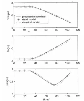
The output average voltage of system, electromagnetic torque and linkage flux obtained by detailed model, classic average value model and the improved model are shown in Fig 3.
Comparing the output results of improved model to the output results of detailed model, show the high accuracy of this model. Although the results of improved and detailed model are quiet the same, but the computation in improved model is very faster than the detailed one. So the detailed model[10,11,12] can be easily replaced by the improved average value model.
Fig.3. Average values of system variable calculated by classic, detailed & the improved model
Consider a switching zone including commutation and conductance time period, to reconstruct the systems instantaneous waveforms. Having obtained analytical results for this zone, complete waveform is accessible by generalizing the relationships for the other zones. First, rotor position is defined as bellows:
=
r
q
~
Positive residueú
ú
ú
û
ù
ê
ê
ê
ë
é
-
-3
3
p
p
b
q
r(18)
Using relation (18) the current
i
as in the commutation period of third switching zone, can be given as:( )
(
[
) (
(
)
)
(
(
)
)
]
(
)
(
)
(
) (
)
(
q b)
p b q
b q
b q y b q y q
2 ~ 2 cos
2 1 3 2 2 ~ 2 cos
2 ~ 2 cos
~ cos ~
sin 3 ~
+ ¢¢
-¢¢ -¢¢ + ¢¢
ú ú û ù ê
ê ë é
÷÷ ø ö çç
è
æ ¢¢
+ ¢¢ + ÷ ø ö ç è æ -+ ¢¢ ¢¢
-¢¢
-+ ¢¢
-¢¢ -¢¢ + ¢¢
+ ¢¢
-+ ¢¢ + =
r d
q d q
dc d q r
d q
r d
q d q
r d r
q r
as
X X X X
I X X X
X
X X X X K i
(19)
Iranian Journal of Electrical & Electronic Engineering, Vol. 2, August 2005. 84
Note that each switching zone begin from
q
~
r=
0
and end to3
~
p
q
r=
. Three-phase currents in the thirdswitching zone including commutation and conductance periods are obtained as follows:
( )
( )
u
I
i
I
i
i
r dc r as dc r as abcs£
ú
ú
ú
û
ù
ê
ê
ê
ë
é
-=
q
q
q
~
~
~
~
(20)u
I
I
i
r dc dc abcs³
ú
ú
ú
û
ù
ê
ê
ê
ë
é
-=
q
~
0
~
(21)
where “~” indicates the variables belongs to the third switching zone. Now by using relation (22):
÷
ø
ö
ç
è
æ
+
-÷
ø
ö
ç
è
æ
+
-=
3
~
3
~
b
p
q
b
p
q
r abcs rr s
qdos
K
i
i
(22)instantaneous currents of q and d-axis are accessible. The currents of all the switching zones can be calculated by the same relation. Derivating of (20) and considering that r r
d
d
d
d
q
q
=
~
, we have:qdos r r s r qdos r r r s qdos r I K d d i d d K i d d ú ú û ù ê ê ë é ÷÷ ø ö çç è æ ÷ ø ö ç è æ -+ + ÷÷ ø ö çç è æ ÷ ø ö ç è æ -+ = 3 ~ 3 ~ p b q q q p b q q (23)
Now using Synchronous machine’s q and d-axis voltage equations that are given below and (20), (21), the instantaneous voltage waveforms are obtained as follows:
q qs r q ds d b r qs s
qs
i
E
d
d
X
i
X
i
r
v
÷÷
+
¢¢
ø
ö
çç
è
æ
¢¢
+
¢¢
÷÷
ø
ö
çç
è
æ
+
=
q
w
w
(24) d ds r d qs q b r ds sds
i
E
d
d
X
i
X
i
r
v
÷÷
+
¢¢
ø
ö
çç
è
æ
¢¢
+
¢¢
÷÷
ø
ö
çç
è
æ
+
=
q
w
w
(25) Phase voltages of synchronous machine are given by:( )
[
r]
qdosr s
abcs
K
v
v
=
q
-1 (26) As converter output voltage in the considered zone iscs bs dc
v
v
v
=
-
, the instantaneous waveform using q- and d-axis voltages in the mentioned zone and (26), can be given as follows :ú
û
ù
ê
ë
é
÷
ø
ö
ç
è
æ
+
+
-÷
ø
ö
ç
è
æ
+
+
=
r qs r dsdc
v
v
v
3
~
cos
3
~
sin
3
q
b
p
q
b
p
(27)
Note that the provided waveforms can be extended for the other zones.
Fig.4. Waveforms reconstruction in steady-state by detailed model
Having instantaneous q- & d-axis currents, electromagnetic torque is constructed by:
r qs r qs r ds r ds
e
i
i
T
=
l
-
l
. As an example, we considered the line –commutated synchronous machine with the parameters that are presented in table (1).In this system, dc current, excitation field
÷
÷
ø
ö
ç
ç
è
æ
=
md fd fd xfdx
v
e
3
& rotor speed are 0.7, 1 & 1 per unit respectively. Also Sub transient reactances of q- and d-axis are 0.328 and 0.172 per unit, respectively.Instantaneous waveforms, converter output voltage, phase current, electromagnetic torque and phase voltage of synchronous machine computed by average-value & detailed model are shown in Fig (4)and (5). It can be seen that the results are quiet the same, while the computation time is considerably reduced.
Iranian Journal of Electrical & Electronic Engineering, Vol. 1 ,No. 2, April 2005. 85
Fig.5. Waveforms reconstruction in steady-state by average value model
3 Instantanous-waveform reconstruction of line-commutated permanent magnet machine
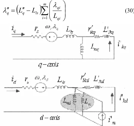
The offered model can be extended for line-commutated permanent magnet synchronous machines. The approach to model line-commutated permanent magnet synchronous machines is similar to the conventional synchronous machine with electrical excitation, the only difference between them lie in the analytical equations [8] related to the equivalent circuit. The equivalent circuit of PMSM is like as conventional synchronous machine with different circuit excitation, as shown in Fig (6). In this figure two axis equivalent circuit of a PMSM is shown. A damper winding on each axis is considered.
Sub transient reactances of q & d axis, according to the two axis equivalent circuit of PMSM shown in Fig 6, is given by:
1
1
1
1
-=
÷÷
ø
ö
çç
è
æ
+
+
=
D
D
=
¢¢
å
ni ldi md
ls d
d d
L
L
L
i
L
l
(28)1
1
1
1
-=
÷
÷
ø
ö
ç
ç
è
æ
+
+
=
D
D
=
¢¢
å
mi lqi mq
ls q
q q
L
L
L
i
L
l
(29)and the sub transient fluxes are given by:
(
)
å
=
÷
÷
ø
ö
ç
ç
è
æ
-¢¢
=
¢¢
mi qi qi ls
q q
L
L
L
1
l
l
(30)Fig.6.Two-axis equivalent circuit of permanent magnet synchronous machines
(
)
÷
÷
ø
ö
ç
ç
è
æ
÷÷
ø
ö
çç
è
æ
-¢¢
=
¢¢
å
=
n
i ldi di ls
d d
L
L
L
1
l
l
(31)Consider line-commutated permanent magnet synchronous machine with presented parameters in table.2.
Table .2 PMSM parameters Rs=0.044
W Lls=1.808 mH
Lmd=40 mH Lmq=22.6 mH
Rkd=0.36
W Llkd=7.5 mH
Rkq=0.52
W Llkq=7.64 mH
To determine system variables’ instantaneous waveforms by the detailed and average-value model, consider dc current & excitation field, 0.25 and 1.15 per unit respectively. Also rotor speed is considered 377 rad/s and q- & d-axis sub transient reactances, 0.323 and 0.336 per unit respectively.
Instantaneous waveforms, converter output voltage, phase current, electromagnetic torque & phase voltage that are computed by the 2 mentioned models are shown in Fig 7 and Fig.8. It can be seen that the results of the offered model is quiet similar to the detailed one, while reducing considerably computation time.
Iranian Journal of Electrical & Electronic Engineering, Vol. 2, August 2005. 86
Fig.7.Reconstructed waveforms in steady-state condition using average value model
4 Conclusion
In this paper firstly improved average value model is presented. This model provides average value that is usually required in control application. As permanent magnet synchronous machines are widely used especially in control application, we applied the improved average value model for the PMSM. Results are nearly close to the calculated values by detailed model. As in some condition, instantaneous waveform and related model is required, such as harmonic investigation, the PMSM model is developed to reconstruct instantaneous waveform. Comparing reconstructed values using improved model to the detailed model results’ show the quite acceptable accuracy of the method, while reducing considerably time calculation.
5 References
[1] W. Qian, S. K. Panda and Jian-Xin Xu "Torque Ripple Minimization in PM Synchronous Motors Using Iterative Learning Control” IEEE Transaction on power electronics energy conversion, vol.19, no.2, March 2004 [2] Yong Li, Jibin Zou and Yongping Lu "Optimum Design of Magnet Shape in Permanent-Magnet
Synchronous Motors" IEEE Transaction on Magnetics, vol.39, no.6, November 2003
Fig.8. Reconstructed waveforms in steady-state condition using detailed model
[3] A. B. Proca, A. Keyhani, A. EL-Antably, W. Luand M. Dai "Analytical Model for Permanent Magnet Motors With Surface Mounted Magnets" IEEE Transaction on energy conversion, vol.18, no.3, September 2003
[4] Kyu-Wang Lee, Doo-Hee Jung and In-Joong Ha "An Online Identification Method for Both Stator Resistance and Back-EMF Coefficient of PMSMs Without Rotational Transducers" IEEE Transaction on industrial electronics, vol.51, no.2, April 2004
[5] J. G. Keuleborough, I. R. Smith, B. A. Fanthom, "Simulation of a Dedicated Aircraft Genertor Supplying a Heavily Rectified Load," IEEE proceeding, Vol. 130, Pt.B No. 6, Nov. 1983, pp. 431-435.
[6] IEEE Committee Report, "Proposed excitation System Definition for Synchronous Machines," IEEE Trans. On Power Apparatus and Systems, Vol. PAS-88, No. 8, August 1969, pp. 1248-1258.
[7] T. H. Rawner and J. G. Kassakian, "Transient Characteristics of large Turbo-alternator Driven Rectifier/Inverter Systems Based on Field test Data," IEEE Trans. On Power Apparatus and Systems, Vol. PAS-104, No. 7, July 1985, pp. 1804-1811.
Iranian Journal of Electrical & Electronic Engineering, Vol. 1 ,No. 2, April 2005. 87 [8] Chee-Mun Ong, "Dynamic Simulation of Electric
Machinery," Prentice Hall, TR, 1998.
[9] S. D. Sudhoff and O. Wazynzuk, "Analysis and Average Value Modeling of Line-Commutated Converter-Synchronous Machine Systems," IEEE Trans. On energy conversion, Vol 8, No. 3, September 1996. [10] M. A. Rahman and T. A, "Dynamic Performance of Permanent magnet Synchronous Motors," IEEE Trans on
Apparatus and Systems, Vol. 103, June 1984, pp. 1277-1282.
[11] A. C. Williamson and K. M. S. Al-Khalidi, "Staring of converter-Fed Synchronous Machine Drives," IEE Proceeding, Vol. 132, Pt.B No. 4, July 1985, pp. 209-214. [12] P. Pillay, and R. Krishnan, "Modeling, Simulation and Analysis of Permanent Motor Drives," IEEE Trans. on Industry Application, Vol. 25, No. 2, March/April 1989, pp. 256-273 and pp. 274-279.