International Journal of Engineering
J o u r n a l H o m e p a g e : w w w . i j e . i rA New Intelligent Controller for Parallel DC/DC Converters
M. Sarvi* a, M. Derakhshana,M. Sedighizadehb
a Department of Electrical Engineering, Imam Khomeini International University, Qazvin, Iran b Faculty of Electrical & Computer Engineering, Shahid Beheshti University, Tehran, Iran
P A P E R I N F O
Paper history: Received 14 May 2013
Received in revised form 26 June 2013 Accepted 22 August 2013
Keywords:
Parallel DC-DC converter PSO PID Controller Immune PID Controller Fuzzy Immune PID Controller
A B S T R A C T
In this paper, the immune controller is used to control the paralleled DC-DC converters. A PID controller is first applied and its coefficient is optimized using an intelligent (PSO) algorithm. Immune controller is then added to PID controller and an immune PID controller is formed. Two methods have been suggested to determine non-linear behavior of immune controller. In the first method, an exponential function is suggested and its unknown coefficient is optimized using PSO algorithm. In the second method, fuzzy logic has been used. Performance of the proposed control methods in the presence of various disturbances is investigated over a sample paralleled DC-DC converter and the effectiveness of the applied immune controller is verified with the comparison of simulation results. The results show that the improvement of system performance with immune PID controller by two suppression function in comparison with the PID controller.
doi: 10.5829/idosi.ije.2014.27.01a.16
1. INTRODUCTION1
Paralleling of DC-DC converters has become a proper method to design power supplies to improve and enhance their power generation capacity, reliability and flexibility [1]. Using paralleled DC-DC converters secures providing large output currents with high reliability in the applications such as mainframe computers, Uninterruptible Power Supplies (UPS), Satellite power system and etc. [2]. Power supplies based on the parallel connection of a number of switching converters offers several advantages to a high-power centralized power supply system. Some of these advantages are as following [3-6]:
v Flexibility in system designation in that the total system power can be increased by raising the number of units
v Having confidence about system's operation in the failure of a unit (higher reliability)
v Less stress on circuit components
v Easier maintenance and repairing and facilitation in cooling performance due to thermal distribution in a larger surface
*Corresponding Author Email:[email protected](M. Sarvi)
v Less occupied space than a single high power converter in the applications which there is space-limitation, using two or lower power converters Selection of the parallel scheme should be done by taking into consideration the complexity, cost, reliability, and etc. In controller designation and putting together various components of the system, different mutual effects between the converters to ensure stability, reliability. In addithin, an appropriate dynamic performance should be considered. One of the main goals in converters paralleling is to share the current between them in an equal and a stable behavior. Parallel DC-DC converters are divided into two categories based on the type of current-sharing: voltage droop methods and active current sharing methods. The second category includes master-slave and average current programming methods [7]. Parallel units are often not similar due to the difference in the components of the circuit and control parameters. If special arrangements are not considered for equal distributing of load current between paralleled units, it is possible that one or more units may be over-current. This reduces system reliability.Therefore, designing of a control method that realizes current distribution between converters in an equal and a good performance as well as performing of
voltage regulation in an appropriate method is necessary [8, 9]. The parallel DC-DC converters have nonlinear behavior, so using of conventional linear controller is not suitable for controlling of them. Intelligent methods are a efficient and suitable method for these systems.
Several studies have been so far made in the field of paralleled DC-DC converters and controlling them [7, 10-18]. Various forms of DC-DC converters parallelization have been classified in terms of circuit theoretic [15]. Classifying parallel converters based on the existing methods has been presented in reference [7]. Chaotic phenomena in parallel converters has been studied [1, 16]. A comparison has been made among PI, PID and Fuzzy controllers to control paralleled DC-DC converter with master-slave current sharing method [17].
The analysis and design of parallel converter with sliding mode control has been presented [2]. A PID controller has been suggested to control paralleled buck converters in that its coefficients have been optimized by GA algorithm [18].
In this paper, an immune controller derived from immune mechanism of living beings has been used to control paralleled DC-DC converters. The purpose of control is to reach an appropriate voltage regulation and sharing load current between the converters in an equal value. A PID controller is applied and its coefficient is optimized using PSO algorithm. Then, immune controller is added to PID controller and an immune PID controller is formed. Two methods have been suggested to determine nonlinear behavior of immune controller. In the first method, an exponential function is suggested and its unknown coefficient is optimized using PSO algorithm. In the second method, fuzzy logic has been used. The effectiveness of the proposed control methods has been studied.
The following sections of this paper are as follows: in section 2, the proposed controllers (suggested-Immune-PID and Fuzzy-(suggested-Immune-PID controllers) as well as PSO-based PID controller are presented. Section 3 presents the simulation results. The dynamic performance of paralleled DC-DC converter in step-response and in set-point changing using the proposed control techniques is also investigated in this section. Finally, the conclusion is presented in section 4.
2. THE PROPOSED IMMUNE CONTROLLER DESCRIPTION
In this section, the proposed intelligent controllers for parallel DC/DC converters are presented. At the first, PSO-based PID controller is introduced. Then, the mechanism of immune system will be introduced in continuous and two proposed controllers (suggested-Immune-PID and Fuzzy-(suggested-Immune-PID controllers) are described.
2. 1. PSO-Based PID Controller PID controller is one of the most known control methods which is widely used in industry due to simple structure, stable performance and easy implementation. The appropriate function of PID controller depends on proper regulation of its coefficients. Classic regulation methods such as Ziegler-Nichols method is not led to favorable results in many industrial facilities due to their complexity and non-linearity. These methods have many disadvantages such as lack of accuracy, long runtime and instability. Therefore, it is desirable that PID controller capabilities be improved by adding a new tool [19]. For this purpose, the PSO algorithm is used.
PSO algorithm [20, 21] is one of the newest heuristic algorithms. This algorithm is a powerful technique for solving problems in which the optimal solution can be expressed as a point or an n-dimension surface in the search space. PSO algorithm optimizes an objective function by doing a population-based search. This population includes potential solutions which are called particle that are a similitude of the population of birds when finding food. The initial value of these particles is determined randomly and then is freely moved in the multi-dimensional space of the problem. In the time of their movement, the speed and position of each particle will change in terms of the best experience of it and that of other particle. This changing rule causes the particle to be moved towards optimal areas and finally, all particles are collected at the optimization point. A flowchart of the classical PSO algorithm is shown in Figure 1. This algorithm has the following steps:
Step 1: Assign an initial value- The speed and position of all particles are randomly set in predetermined or authorized range.
Step 2: Updating the particle velocity- The velocity of all particles are updated in each iteration as the following:
( )
(
)
( )
(
)
1
1 1 ,
2 2
. . 0 .
. 0 .
t t t
i i i best i
t best i
v v c rand P x
c rand G x
w
+ = +
-+ - (1)
where, t i
x and t i
v are the position and velocity of the ith particle, respectively. Pi best, is the best previous position in which the best objective function obtained for the ith particle, Gbest is the position that the best answer has been obtained so far by the total population,
The particle velocity in this algorithm has a maximum value and if its speed is higher than it, its value in each iteration will be reduced to the maximum amount. Step 3: Updating the position- In each iteration, the
positions of all particles are updated as the following:
1 1
t t t
i i i
x + =x +v + (2)
After updating the position of each particle, it must be checked that the position of all particle are maintained in the authorized range.
Step 4: Updating memory- Pi best, and Gbest are updated, that is:
( )
(
)
, ,
i best i i i best
P ¬x if f x >f P (3)
( )
(
)
best i i best
G ¬x if f x >f G (4)
In which, f( )xi is an optimization objective function. Step 5: Investigation of algorithms termination
conditions- The steps of 2-4 will be iterated until certain conditions are fulfilled. This condition can be a specific number of iterations and or fixing Gbest within a tandem repeat.
Gbest will be the best response and f
(
Gbest)
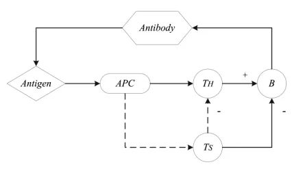
will be the final optimal value at the end.2. 2. Immune-PID Controller Biological immune system is a control system which has high strength and self-regulation on environments with complex disturbances and uncertainties. This controller is inspired by human body's defense mechanism. Schematic of the immune system is shown in Figure 2. Antigens are identified by antigen presenting cells (APC) after the invasion to the organisms, then a message will be sent to T cells. After that, B cells are stimulated by T cells after receiving the message and finally produce antibodies rapidly to eliminate the antigens. When the number of antigens increases, the number of helper T cells will also be increased. Thus, the body can produce more B cells to protect itself. Suppressor T cells will be increased by reducing antigens and as a result the number of B cells will be reduced. Immune system will be balanced after a time [22]. By considering the effect of helper T cells on B cells as h nT
( )
and the effect of suppressor T cells on B cells as sT( )
n and by defining the antigens in nthiteration as e( )n , the total stimulation of B cells is:
( )
T( )
T( )
S n =h n -s n (5)
where,
( )
1 ( )T
h n =ce n (6)
( )
2(
( )
,( )
)
( )T
s n =c f S n DS n e n (7)
In the above equations,
c
1andc
2 are motivation and suppression coefficients, respectively. DS n( )indicates the amounts of S n( )
changes. f( )
.
is the limited nonlinear function in [-1, 1] range that shows the effect of suppressor T cells over B cells which is called suppression function. By substitution (6) and (7) into (5), Equation (8) is obtained:( )
1 1(
( )
,Δ( )
)
( )S n =c éë -hf S n S n ùûe n (8)
where, h=c c2/ 1.
Figure 1. Flowchart of the conventional PSO algorithm
For a feedback control system, if control error e n( ) between the set-point and control system output is supposed as the antigens ee( )n and if control variables
( )
u n is supposed as total motivation of B cells, Equation (9) will be as follows:
( )
1 1(
( )
,Δ( )
)
( )u n =c éë -hf u n u n ùûe n (9)
where,
c
1 is applied for response speed control andh
for stability. Rapid response and good stability of system can be obtained by appropriate selection ofc
1and
h
.Body immune mechanism-based controller
described in Equation (9) is equivalent to a non-linear P controller with variable proportional gain. It also refers as immune proportional controller. This controller cannot compensate for the error caused by noise or nonlinear interference. For this reason, it is not often used by isolation. However, PID controller considers previous, present and future information associated with the error in a comprehensive method. Therefore, system's control performance can be improved by the connection of the immune controller to classic PID controller [23, 24]. Discrete PID controller is written by the following expression
:
( )
* 1 1 ( )
1 d i p
K
K T z
e n K e n
z T z
-æ ö
= ç + + ÷
-è ø (10)
where, K p is the proportional coefficient, Kiis integral coefficient, Kdis the derivation coefficient and T is the sampling period. The relationship between input e(n) and output u(n) of Immune- PID controller is as follows
:
( )
( )
(
( )
( )
)
( )
( )
(
)
( )
* 1 ,Δ
1
1 , 1
1
é ù
= ë - û
-æ ö
é ù
= ë - D û´ +ç + ÷
-è ø
d i p
u n e n f u n u n
K
K T z
K f u n u n e n
z T z
h
h (11)
The block diagram of Immune- PID controller is shown in Figure 3.
Figure 3. Block diagram of Immune-PID controller
To use immune controller, suppression function must be first determine. In this paper, following function is proposed. In Equation (12), c coefficient determines the operation range of u variable.
( )
( )22 cu 1
f u = e- - (12)
By replacing Equation (12) in (11), Equation (13) will be obtained:
( )
(
)
( )
2
( )
1 2 1
1 1 1 p d i cu
u n K e
K
K T z
e n
z T z
h
-é ù
= ê - - ú
ë û
-æ ö
´ç + + ÷
-è ø
(13)
To determine
c
andh
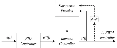
optimum coefficients, PSO algorithm is used.2. 3. Fuzzy-Immune-PID Controller Due to an appropriate approximation of fuzzy logic [25], a fuzzy controller to realize suppression function of immune controller is used in this section. The first step in designing of fuzzy controller is decision on which state variable indicating the dynamic performance should be chosen as controller input signal. The correct choice of linguistic variables which form fuzzy controller rules is a very important factor in the performance of fuzzy system.
The proposed fuzzy controller has two inputs and one output. Input one (u) here is the controlling signal applied to PMW block, and the second input (du) is the changes in input one (u) which is calculated from the following equation:
( ) ( 1)
du =u k -u k- (14)
Fuzzy output signals are calculated in terms of fuzzy membership functions which depend on these variables. Inputs and outputs membership functions are shown in Figures 4-6. Five membership functions are considered for each input and output. Fuzzy rule base is given in Table 1. Each rule indicates as expressions NB: Negative Big, NS: Negative Small, Z: Zero, PS: Positive Small, PB: Positive Big.
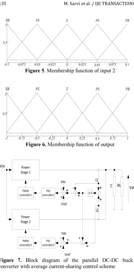
Figure 5. Membership function of input 2
Figure 6. Membership function of output
Figure 7. Block diagram of the parallel DC-DC buck converter with average current-sharing control scheme
3. SIMULATION RESULTS AND DISCUSSIONS
In order to investigate the performance and accuracy of the proposed controller, a system includes two parallel DC-DC converters, a DC voltage source and a resistive load are considered, simulated and analyzed as well as control unit. The block diagram of the parallel DC-DC converter is shown in Figure 7. This system consists of two buck converters with parallel connections in input and output. Average current method was applied as the control strategy for current-sharing. Each converter has a controller which its input is the sum of errors of output voltage and current of that. Its output is the control signal which applies on the PWM block. Finally, in order to reach desired characteristics, the duty cycle of the associated converter is determined. Input voltage is equal to 5 V, reference voltage is 2 V, resistance of load is 2 ohm and switching frequency is 20 kHz. Thus, in
steady state, the output current is one ampere which is half ampere for each of two parallel converters assuming they are identical. First, an objective function for evaluating the performance of the system should be selected. Some conventional indexes are as following:
( )
1
0
J IA E e t dt
¥
= =
ò
(15)( )
2
0
J ITAE t e t dt
¥
= =
ò
(16)( )
2 3
0
J ISE e t dt
¥
= =
ò
(17)( )
2 40
J ITSE te t dt
¥
= =
ò
(18)2 2 5
0 ( )
J ISTSE t e t dt
¥
= =
ò
(19)( )
2 2
6
0
( )
J ISTES t e t dt
¥
= =
ò
(20)In ISE and ITSE indexes, use of square of the error penalizes large errors more than smaller ones. In ITSE and ITAE indexes, multiplying the error by the time, weights errors which exist after a long time much more heavily than those at the start of the response. ISTSE and ISTES performances indexes, both consider a higher power of time and error. As a result, they further reduce the rise time and the settling time. Two other performance indexes used, which include rise time (
t
r), settling time (t
s), overshoot (Mp), Steady state error (ss
E ) and current-sharing error (E CS( )) are:
(
)
(
)
(
)
7 1 . p ss . s r
J = -e-b M +E +e-b t -t (21)
(
)
28 1. p 2.s 3. ( )
J = K M +K t +K E CS (22)
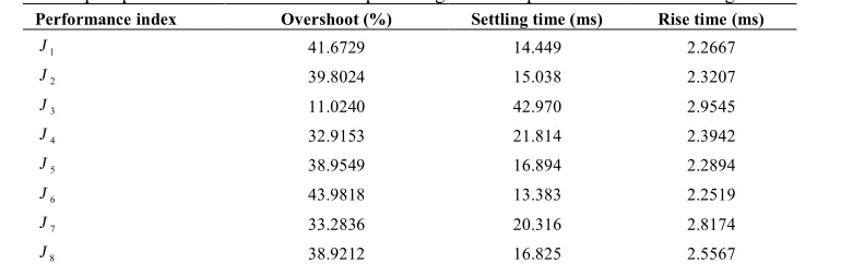
Using any of the above performance indexes as the objective function of PSO algorithms, different coefficients for the PID controllers is achieved. Step response characteristics of the output voltage, including rise time, settling time and overshoot for each performance indices is given in Table 2.
TABLE 2. Step response characteristics of the output voltage for each performance indices using PID controller Rise time (ms)
Settling time (ms) Overshoot (%) Performance index 2.2667 14.449 41.6729 1 J 2.3207 15.038 39.8024 2 J 2.9545 42.970 11.0240 3 J 2.3942 21.814 32.9153 4 J 2.2894 16.894 38.9549 5 J 2.2519 13.383 43.9818 6 J 2.8174 20.316 33.2836 7 J 2.5567 16.825 38.9212 8 J
TABLE 3. Comparison of step-response characteristics of output voltage using the three control methods ITSE Rise Time (ms)
Settling Time (ms) Overshoot (%) Control Method 4.9230e-5 2.3393 20.208 35.0502 PSO-based PID 1.0377e-5 2.4052 11.169 7.6175 Suggested-Immune-PID 1.1069e-5 2.3814 7.9252 11.5172 Fuzzy-Immune-PID
TABLE 4. Performance index ITSE for set- point changes conditions
Sudden failure of a converter Change in output load
Change in reference voltage Change in input voltage
Control method 1.6234e-5 5.4404e-4 1.82294e-3 3.1219e-4 PSO-based PID 3.1345e-6 2.6981e-4 1.67922e-3 9.6981e-5 Suggested-Immune-PID 1.9826e-6 2.6655e-4 1.65797e-3 2.1217e-5 Fuzzy-Immune-PID
Considering Table 2, observed that using ITSE as the performance criteria, a better balance between settling time and overshoot is established and the ITSE seems to function better than others. Therefore, in the following, objective function of J4 is used. In order to investigate performance of the proposed method, two following cases are simulated and analyzed:
Case 1- Startup of the system
Case 2- Comparison of the three control methods in set point changes conditions
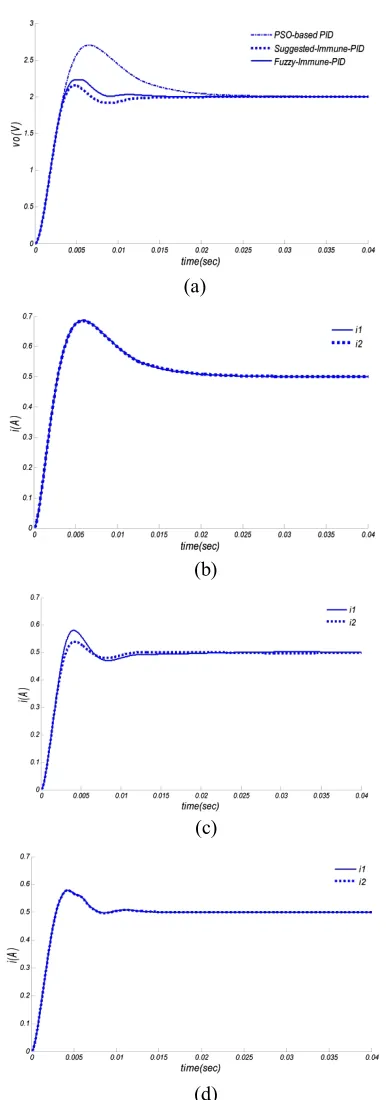
3. 1. Startup of the System The output voltage of DC-DC converters in startup conditions for each of three presented control methods is shown in Figure 8 (a). For better comparison, the step response characteristics of output voltage, including the settling time, overshoot, rise time, and performance index of ITSE for the three controllers is presented in Table 3. To evaluate the performance of current sharing, the current diagram of two parallel converters is shown in Figure 8 (b-d). By comparing the results in Table 3, it can be seen that using Suggested-Immune-PID controller, in comparison with PSO-PID, overshoot is dropped more than 78%. In addition, settling-time is decreased about 44.7% and rise-time is increased about 3%. The performance index (ITSE) is also dropped about 79%, which is considerable. Using Fuzzy-Immune PID, overshoot is dropped over 67% in comparison with PID. Furthermore, settling-time is declined 61% and rise-time is increased slightly about 2%. The performance index (ITSE) is also dropped
77.5%. In comparison of Fuzzy-Immune-PID controller with Suggested-Immune-PID controller, it is observed that overshoot slightly increased and settling-time and rise-time are slightly dropped. Performance index (ITSE) is also slightly increased.
The results of Table 3 represent negligible difference of the controllers’ performance index of Suggested-Immune-PID and Fuzzy-Suggested-Immune-PID in startup of the system. However, with regard to index performance (ITSE), it can be said Suggested-Immune-PID controller had more favorable response. Figures 8 (b-d) show that for almost all proposed control methods, parallel converter under study in which average current programming has been used for distribution had pretty well current-sharing performance. Only when using the Suggested-Immune-PID controller, currents of the two parallel converters are slightly different that becomes zero after the system reaches steady state. The output current is also divides well between two converters.
(a)
(b)
(c)
(d)
Figure 8. Startup of the system: (a) output voltages using 3
controllers (b) converter’s currents using PSO-based PID (c)
converter’s currents using Suggested-Immune-PID (d)
converter’s currents using Fuzzy-Immune-PID controller
3. 2. 1. Chang in Output Load After starting up the system, at the moment t=0.04 sec, output load is reduced by 50 percent. After transient state, the output
voltage is tuned at 2 volts, and output current doubles. As a result, current in each of the two parallel converter increases to one ampere. Figure 9 (a) shows the output voltage of converters. Figures 9 (b-d) show the input current of converters. Figures 9 (b-d) show that the current sharing using PSO-based PID and Fuzzy-Immune-PID controllers is well done and in Suggested-Immune-PID controller, only in the system transient conditions a slight difference is observed in the two converters currents. Comparing results of Table 4 show the weakest performance in PSO-based PID controller and the best performance in the Fuzzy-Immune-PID controller with little difference from the Suggested-Immune-PID controller.
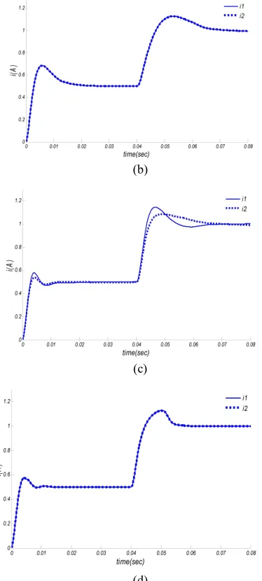
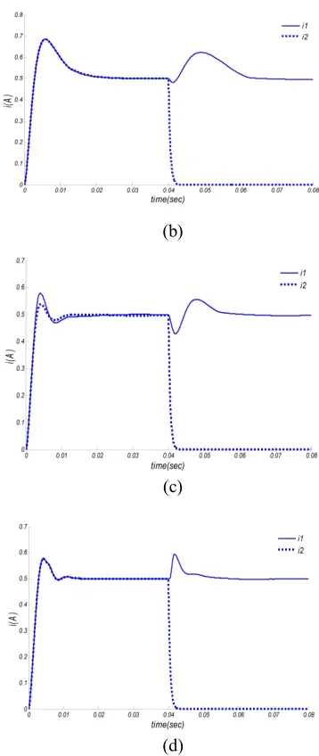
3. 2. 2. Change in Reference Voltage By increasing the reference voltage from 2 V to 4 V at moment t=0.04 sec, current of each converter should increase to one ampere. Figure 10 (a) shows the output voltage of converters. Figures 10 (b-d) show the input current of converters. From Figures 10 (b-d), it is observed that current sharing has been done well by all the three controllers. Figure 10 (a) and Table 4 show nearly similar performance of the three controllers. However, comparing of the ITSE performance indexes shows that using Fuzzy-Immune-PID gives a few better responses. 3. 2. 3. Change in Input Voltage At the moment t=0.04 sec, input voltage increases from 5 V to 10 V. Figure 11 (a) shows the output voltage of converters. Figures 11 (b-d) show the input current of converters. Figures 11 (b-d) show that the current sharing using PSO-based PID and Fuzzy-Immune-PID controllers has been done well. For Suggested-Immune-PID Controller, in the system transient state, significant difference is observed in the two converters current; but, they are equal in steady state. Table 4 and the output voltage (Figure 11 (a)) show the use of Suggested-Immune-PID controller which has much better response than the PSO-based PID controller. In addition, in Fuzzy-Immune-PID controller, response of the system is improved significantly compared to the other two controllers, So that ITSE performance index is dropped 93% compared to PSO-based PID, and 78% compared to Suggested-Immune-PID controllers.
(b)
(c)
(d)
Figure 9. Change in output load: (a) output voltages using 3
controllers (b) converter’s currents using PSO-based PID (c)
converter’s currents using Suggested-Immune-PID (d)
converter’s currents using Fuzzy-Immune-PID controller
(a)
(b)
(c)
(d)
Figure 10. Change in reference voltage: (a) output voltages
using 3 controllers (b) converter’s currents using PSO-based
PID (c) converter’s currents using Suggested-Immune-PID (d)
converter’s currents using Fuzzy-Immune-PID controller
(b)
(c)
(d)
Figure 11. Change in Input voltage: (a) output voltages using 3
controllers (b) converter’s currents using PSO-based PID (c)
converter’s currents using Suggested-Immune-PID (d)
converter’s currents using Fuzzy-Immune-PID controller
(a)
(b)
(c)
(d)
Figure 12. Sudden failure of a converter: (a) output voltages
using 3 controllers (b) converter’s currents using PSO-based
PID (c) converter’s currents using Suggested-Immune-PID (d)
converter’s currents using Fuzzy-Immune-PID controller.
4. CONCLUSION
unknown coefficient is optimized using PSO algorithm. In the second method, fuzzy logic has been used. The results show that adding immune controller to PID controller is not only simple, but it has significant impact in system response improvement. However, the capability of immune controller is determined by the appropriate designation and choosing of suppression function. Two methods have been proposed for designation of suppression function (the proposed exponential function and Fuzzy logic).
The results show the improvement of system performance with Immune PID controller by the two suppression function in comparison with the PID controller. In an overall conclusion, it can be said that in a condition that the simplicity of a system is highly important along with an appropriate performance of control system, Suggested-Immune-PID controller seems more appropriate, but if the improvement of control system performance, especially its response in the conditions of set-point change is important, fuzzy-immune-PID controller is suggested.
5. REFERENCES
1. Iu, H. and Tse C.K., “Study of low-frequency bifurcation phenomena of a parallel-connected boost converter system via simple averaged models”, IEEE Transactions on Circuits and Systems I: Fundamental Theory and Applications , Vol. 50, (2003), 679-685.
2. López, M. and et al., “Current distribution control design for paralleled DC/DC converters using sliding-mode control”, IEEE Transactions on Industrial Electronics, Vol. 51, (2004), 419-428.
3. Chen, W. and et al., “DC/DC conversion systems consisting of multiple converter modules: stability, control, and experimental verifications”, IEEE Transactions on Power Electronics, Vol. 24, (2009), 1463-1474.
4. Garcera, G. and et al. “Analysis and design of a robust average current mode control loop for parallel buck DC-DC Converters to reduce line and load disturbance”, IET Electric Power Applications, Vol.151, (2004), 414-424.
5. Garcerá, G., Pascual, M. and Figueres, E., “Robust average current-mode control of multimodule parallel DC-DC PWM converter systems with improved dynamic response”, IEEE Transactions on Industrial Electronics, Vol. 48, (2001), 995-1005.
6. Kim, J.W., Choi, H.S. and Cho, B.H., “A novel droop method for converter parallel operation”, IEEE Transactions on Power Electronics, Vol. 17, (2002), 25-32.
7. Luo, S. and et al., “A classification and evaluation of paralleling methods for power supply modules”, Proceedings of 30th Annual
IEEE Power Electronics Specialists Conference, PESC 99 (1999).
8. Garcia, P.D. and et al., “Sliding mode control for current distribution in DC-DC converters connected in parallel”,
Proceedings of 27th Annual IEEE Power Electronics Specialists
Conference, PESC'96 Record, (1996).
9. Nair, M.D. and Sanakaran, R., “Simulation and experimental verification of closed loop operation of buck/boost DC-DC converter with soft switching”, International Journal of Engineering (IJE), Transaction C: Aspects, Vol. 25, (2011), 267-274.
10. Chae S. and et al., “Digital current sharing method for parallel interleaved dc-dc converters using input ripple voltage”, IEEE Transactions on Industrial Informatics, Vol. 8, (2012), 536-544.
11. Beccuti, A.G. and et al. “A decentralized explicit predictive control paradigm for parallelized DC-DC circuits”, IEEE Transactions on Control System Technology, Vol. 21, (2013), 136-148.
12. Anand, S. and Fernandes, B.G., “Modified droop controller for paralleling of DC-DC converters in stand alone DC system”,
IET Power Electronics, Vol.5, (2012), 782-789.
13. Wang, J.B., “Parallel DC-DC converters system with a novel primary droop current sharing control”, IET Power Electronics, Vol.5, (2012), 1569-1580.
14. Tsang C. W. and et al., “Active current ripple cancellation in parallel connected buck converter modules”, IET Power Electronics, Vol.6, (2013), 721-731.
15. Huang, Y. and Tse, C., “Circuit theoretic classification of parallel connected DC–DC converters”, IEEE Transactions on Circuits and Systems I: Vol. 54, (2007), 1099-1108.
16. Natsheh, A.N., Kettleborough, J.G., and Nazzal, J.M., “Analysis, simulation and experimental study of chaotic behaviour in parallel-connected DC–DC boost converters”, Chaos, Solitons & Fractals, Vol. 39, (2009), 2465-2476.
17. Tomescu, B. and VanLandingham, H., “Improved large-signal performance of paralleled DC-DC converters current sharing”,
IEEE Transactions on Power Electronics, Vol. 14, (1999), 573-577.
18. Cheng, C.H., Cheng, P.J. and Xie, M.J., “Current sharing of paralleled DC–DC converters using GA-based PID controllers”,
Expert Systems with Applications, Vol. 37, (2010), 733-740. 19. Gaing, Z.L., “A particle swarm optimization approach for
optimum design of PID controller in AVR system”, IEEE Transactions on Energy Conversion, Vol. 19, (2004), 384-391. 20. Kennedy, J., Eberhart, R., “Particle swarm optimization”,
Proceedings of IEEE International Conference on Neural Networks. (1995).
21. Sadafi, M.H. and et al., “Multi objective optimization of solar thermal energy storage using hybrid of particle swarm optimization”, International Journal of Engineering (IJE) Transactions B: Application, Vol. 24, (2011), 367-376. 22. Tiwari, S.K., Kaur, G., and Singh, H., “Analysis of fuzzy PID
and immune PID controller for three tank liquid level control”,
International Journal of Soft Computing and Engineering , Vol. 1, (2011), 185-189.
23. Ren, X.Y. and et al., “Application of improved fuzzy immune PID controller to bending control system”, International Journal of Iron and Steel Research, Vol. 18, (2011), 28-33. 24. Su, Y.X. and et al., “Fuzzy-immune PID control for AMB
systems”, Wuhan University Journal of Natural Sciences, Vol. 11, (2006), 637-641.
A New Intelligent Controller for Parallel DC/DC Converters
M. Sarvia, M. Derakhshana,M. Sedighizadehb
a Department of Electrical Engineering, Imam Khomeini International University, Qazvin, Iran b Faculty of Electrical & Computer Engineering, Shahid Beheshti University, Tehran, Iran
P A P E R I N F O
Paper history: Received 14 May 2013
Received in revised form 26 June 2013 Accepted 22 August 2013
Keywords:
Parallel DC-DC converter PSO PID Controller Immune PID Controller Fuzzy Immune PID Controller
هﺪﯿﮑﭼ
يﺎﻫلﺪﺒﻣلﺮﺘﻨﮐياﺮﺑﻦﻤﯾاهﺪﻨﻨﮐلﺮﺘﻨﮐزا،ﻪﻟﺎﻘﻣﻦﯾارد
DC-DC
ﺖﺳاهﺪﺷهدﺎﻔﺘﺳا
.
هﺪﻨﻨﮐلﺮﺘﻨﮐﮏﯾاﺪﺘﺑا
PID
درﻮﻣ
ﺪﻨﻤﺷﻮﻫﻢﺘﯾرﻮﮕﻟاﮏﯾﺎﺑنآﺐﯾاﺮﺿودﺮﯿﮔﯽﻣراﺮﻗهدﺎﻔﺘﺳا
)
تارذعﺎﻤﺘﺟايزﺎﺳﻪﻨﯿﻬﺑ
(
دﻮﺷﯽﻣﻪﻨﯿﻬﺑ
.
هﺪﻨﻨﮐلﺮﺘﻨﮐﺲﭙﺳ
هﺪﻨﻨﮐلﺮﺘﻨﮐﻪﺑﻦﻤﯾا
PID
هﺪﻨﻨﮐلﺮﺘﻨﮐﮏﯾودﻮﺷﯽﻣﻪﻓﺎﺿا
PID
دﺮﯿﮔﯽﻣﻞﮑﺷﻦﻤﯾا
.
ﯽﻄﺧﺮﯿﻏرﺎﺘﻓرﻦﯿﯿﻌﺗياﺮﺑشورود
دﻮﺷﯽﻣدﺎﻬﻨﺸﯿﭘﻦﻤﯾاهﺪﻨﻨﮐلﺮﺘﻨﮐ
.
ﻢﺘﯾرﻮﮕﻟازاهدﺎﻔﺘﺳاﺎﺑنآﺐﯾاﺮﺿوددﺮﮔﯽﻣدﺎﻬﻨﺸﯿﭘﯽﯾﺎﻤﻧﻊﺑﺎﺗﮏﯾ،لواشوررد
PSO
ﺪﻧﻮﺷﯽﻣﻪﻨﯿﻬﺑ
.
دﻮﺷﯽﻣهدﺎﻔﺘﺳايزﺎﻓﻖﻄﻨﻣ،مودشوررد
.
ﻒﻠﺘﺨﻣتﻻﻼﺘﺧارﻮﻀﺣرديدﺎﻬﻨﺸﯿﭘلﺮﺘﻨﮐيﺎﻫشوردﺮﮑﻠﻤﻋ
لﺪﺒﻣﮏﯾرد
DC-DC
ﺷﻪﺋاراهﺪﻨﻨﮐلﺮﺘﻨﮐﯽﯾارﺎﮐودﻮﺷﯽﻣﯽﺳرﺮﺑﻪﻧﻮﻤﻧيزاﻮﻣ ﯽﺳرﺮﺑدرﻮﻣيزﺎﺳﻪﯿﺒﺷﺞﯾﺎﺘﻧﻪﺴﯾﺎﻘﻣﺎﺑهﺪ
دﺮﯿﮔﯽﻣراﺮﻗ
.
هﺪﻨﻨﮐلﺮﺘﻨﮐﻪﮐﺪﻨﻫدﯽﻣنﺎﺸﻧﺞﯾﺎﺘﻧ
PID
هﺪﻨﻨﮐلﺮﺘﻨﮐﺎﺑﻪﺴﯾﺎﻘﻣرديدﺎﻬﻨﺸﯿﭘشورودﺎﺑﻦﻤﯾا
PID
ﻪﺼﺨﺸﻣ
ﺪﻨﻨﮐﯽﻣﺮﺘﻬﺑارﻢﺘﺴﯿﺳ
.