Ann. Geophys., 26, 3525–3543, 2008 www.ann-geophys.net/26/3525/2008/ © European Geosciences Union 2008
Annales
Geophysicae
Magnetic configurations of the tilted current sheets in magnetotail
C. Shen1, Z. J. Rong1,2, X. Li3, M. Dunlop4,5, Z. X. Liu1, H. V. Malova6, E. Lucek5, and C. Carr5
1State Key Laboratory of Space Weather, Center for Space Science and Applied Research, Chinese Academy of Sciences,
Beijing 100190, China
2College of Earth Science, Graduate University of Chinese Academy of Sciences, Beijing, 100049, China 3Laboratory for Atmosphere and Space Physics, University of Colorado, Boulder, USA
4Rutherford Appleton Laboratory, Chilton, DIDCOT, Oxfordshire OX11 0QX, UK 5Imperial College of Science, Technology and Medicine, London, UK
6Nuclear Physics Institute, Moscow State University, 119899 Moscow, Russia
Received: 7 May 2008 – Revised: 15 August 2008 – Accepted: 29 September 2008 – Published: 17 November 2008
Abstract. In this research, the geometrical structures of tilted current sheet and tail flapping waves have been anal-ysed based on multiple spacecraft measurements and some features of the tilted current sheets have been made clear for the first time. The geometrical features of the tilted current sheet revealed in this investigation are as follows: (1) The magnetic field lines (MFLs) in the tilted current sheet are generally plane curves and the osculating planes in which the MFLs lie are about vertical to the equatorial plane, while the normal of the tilted current sheet leans severely to the dawn or dusk side. (2) The tilted current sheet may become very thin, the half thickness of its neutral sheet is generally much less than the minimum radius of the curvature of the MFLs. (3) In the neutral sheet, the field-aligned current density be-comes very large and has a maximum value at the center of the current sheet. (4) In some cases, the current density is a bifurcated one, and the two humps of the current density of-ten superpose two peaks in the gradient of magnetic strength, indicating that the magnetic gradient drift current is possibly responsible for the formation of the two humps of the current density in some tilted current sheets. Tilted current sheets often appear along with tail current sheet flapping waves. It is found that, in the tail flapping current sheets, the minimum curvature radius of the MFLs in the current sheet is rather large with values around 1RE, while the neutral sheet may be very thin, with its half thickness being several tenths of RE. During the flapping waves, the current sheet is tilted substantially, and the maximum tilt angle is generally larger than 45◦. The phase velocities of these flapping waves are several tens km/s, while their periods and wavelengths are several tens of minutes, and several earth radii, respectively.
Correspondence to: C. Shen
These tail flapping events generally last several hours and oc-cur during quiet periods or periods of weak magnetospheric activity.
Keywords. Magnetospheric physics (Magnetospheric con-figuration and dynamics; Magnetotai; Magnetotail boundary layers) – Space plasma physics (Discontinuities)
1 Introduction
3526 C. Shen et al.: Tail tilted current sheets they have argued are generated by some impulsive source
in the center of tail and propagating toward the flanks with velocities of a few tens km/s. Joint observations of Double Star Project (Liu et al., 2005) and Cluster (Escoubet et al., 2001) revealed that kink-like waves along the Y-axis can be observed at the geocentric distance of 11–19RE (Zhang et al., 2005). The locations of the occurrence of the tail flap-ping motion may be in the range−11RE>X>−30RE(Lui et al., 1978; Sergeev et al., 1993, 2006; Runov et al., 2005a). Sergeev et al. (2006) have found statistically that, similar to BBFs, current sheet flapping events tend to occur at the cen-ter of tail, but these two processes have no one-to-one local correspondence. Some theoretical explanations to the causes of CS flapping motion have been proposed (Nakagawa and Nishida, 1989; Golovchanskaya and Maltsev, 2005; Malova et al., 2007; Erkaev et al., 2008). Nakagawa and Nishida (1989) have suggested that the kink-like waves propagating towards the flanks might be excited by the Kelvin-Helmholtz instability at the plasma sheet. Golovchanskaya and Maltsev (2005) have argued the flapping motions could be the eigen oscillation of the plasma confined in the curvilinear magnetic field in the plasma sheet. Malova et al. (2007) have specu-lated the flapping wave might be induced by the asymmetric ion flow in the Northern and Southern Hemispheres. Erkaev et al. (2008) have interpreted it as a new kind of MHD wave related to a coexistence of two gradients of the tangential and normal magnetic field components of the current sheet.
The features of the tilted CS associated with the tail CS flapping motion have drawn much attention and are still un-der investigation. For the conventional tail current sheet (Lui, 2004, and the references therein), its normal is approximately along the south-north direction and the current sheet is al-most parallel to the equatorial plane. The osculating planes of the magnetic field lines (MFLs) in the CS are about ver-tical to the equatorial plane (Shen et al., 2003) and the cur-rent inside of the CS is duskward and also cross-wise to the field. We may call this type of CS a normal current sheet. Sometimes, the normal current sheet may be approximated with Harris model (Harris, 1962; Lui, 2004; Thompson et al., 2005). The tail CS flapping motion may change the orientation of the current sheet and lead to the formation of the tilted current sheet (Sergeev et al., 2003, 2004; Vol-werk et al., 2003; Runov et al., 2005a, b, 2006; Nakamura et al., 2006; Petrukovich et al., 2006). For the tilted current sheet associated with the tail flapping motion, its normal de-viates from the northern direction and sometimes the tilted current sheet can be nearly vertical to the equatorial plane. Petrukovich et al. (2006) have argued that the tilted current sheet is caused by the slippage of the magnetic flux tubes in the flapping plasma sheet and found that the magnetic ampli-tude and magnetic gradient are approximately proportional to the steepness of the current sheet.
Nevertheless the 3-D magnetic geometry of the flapping current sheet is still not so clear. Obviously, in order to re-solve this issue, new analysis methods should be employed
to better reveal the detailed quantitative properties of the tilted current sheet. Here we will take advantage of Cluster multiple-point observations to quantitatively and explicitly investigate the features of the tilted current sheets, such as the geometric structure of the MFLs (including their curva-ture, binormal, etc.), the orientation of the current sheet, and the current density distribution in the tilted current sheets. The nature of tail flapping motions has also been explored and their possible mechanism has been given.
2 Analysis on the magnetic features of tilted current sheet
The four-point observations of Cluster have offered an excel-lent and unprecedented opportunity to study magnetospheric dynamics (Escoubet et al., 2001). With Cluster magnetic measurements (Balogh et al., 2001) and the previously devel-oped multiple point data analysis methods (Chanteur, 1998; Harvey, 1998; Dunlop and Woodward, 1998; Dunlop et al., 2002; Shen et al., 2003, 2007a, b, 2008a, b; Shi et al., 2005, 2006; Sonnerup et al., 2008), the current density, magnetic gradient and magnetic field geometry, and motion of the sheet, can be found. The actual structures of the tail cur-rent sheet can often be revealed as distinct from the temporal variations.
To illustrate the main features of magnetic geometry of the tilted current sheet, two typical cases have been studied in details in Sect. 2.1. In Sect. 2.2, the properties of the tail flapping waves have been investigated.
2.1 Features of the tilted current sheet
In this section, we will analyse two single tilted current sheet crossing events on 5 August 2001 and 3 August 2004 and un-cover the general geometrical features of this kind of current sheet by using newly developed, multi-point data analysis ap-proaches (Shen et al., 2003, 2007a, b, 2008a). In this study, the magnetic field data of the Cluster four spacecraft have a time resolution of 4 s, where GSM coordinates are used here. It is useful to define the spherical coordinate for any vector direction (θ, ϕ)in the frame of GSM. The coordinate θ(0◦≤θ≤180◦)is the angle between the positive z-axis and the vector direction, and referred to as the polar angle; The coordinate φ (0◦≤φ<360◦) is the angle between the posi-tive x-axis and the line from the vector direction projected onto the xy-plane, and referred to as the azimuth angle. For example, the dawn direction or−y-direction is atθ=90◦and ϕ=270◦, while the dusk direction or +y direction is atθ=90◦ andϕ=90◦.
2.1.1 Case on 5 August 2001
C. Shen et al.: Tail tilted current sheets 3527
12
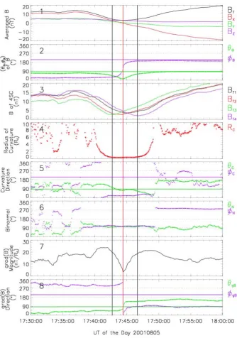
Figure 1a The geometric structure of the tilted current sheet during one Cluster crossing event on 5 Aug 2001. Panel 1: the
magnetic field at the center of Cluster tetrahedron as are the average of those at the four spacecraft; panel 2: the directional angle
(
θ
B,ϕ
B) of the magnetic field at the center of Cluster tetrahedron; panel 3: magnetic strengths observed by the 4 spacecraft of [image:3.595.130.465.59.536.2]Cluster; panel 4: the radius of curvature
R
c; panel 5: the direction angles (θ
c,ϕ
c) of the curvature of the MFLs, that is alsoFig. 1a. The geometric structure of the tilted current sheet during one Cluster crossing event on 5 August 2001. Panel 1: the magnetic field
at the center of Cluster tetrahedron as are the average of those at the four spacecraft; panel 2: the directional angle (θB,ϕB) of the magnetic
field at the center of Cluster tetrahedron; panel 3: magnetic strengths observed by the 4 spacecraft of Cluster; panel 4: the radius of curvature Rc; panel 5: the direction angles (θc,ϕc) of the curvature of the MFLs, that is also the direction angles of the principal normal; panel 6: the
direction angles (θN,ϕN) of the normal of the osculating plane, or the binormal, of the MFLs; panel 7: the value of the gradient of magnetic
field strength; panel 8: the directional angle (θgB,ϕgB) of the gradient of magnetic field strength. GSM coordinates are used here. The
polar angle and azimuthal angle of the position vector of Cluster in GSM are also plotted in the panel of∇B/Bdirection as green and violet horizontal lines, respectively.
and the magnetospheric activity is very weak with a rather low AE index. At the time of this event, Cluster is about 19.3REaway from the Earth center and the polar angle and azimuthal angles of its position in GSM are (θ, ϕ)=(85◦, 206◦), respectively. The Cluster tetrahedron was nearly
reg-ular, and the averaged distance between its nodes and the barycenter is about 1200 km.
3528 C. Shen et al.: Tail tilted current sheets
14
Figure 1b The geometric structure of the tilted current sheet during one Cluster crossing event on 5 Aug 2001. Panel 1: the
magnetic field at the center of Cluster tetrahedron as are the average of those at the four spacecraft; panel 2: the maximum, medium
and minimum rotation rate of the magnetic field; panel 3: the directional angles (
θ
e1,ϕ
e1) of the first eigenvector eˆ(1); panel 4: [image:4.595.134.465.59.527.2]the directional angles (
θ
e2,ϕ
e2) of the second eigenvector eˆ(2); panel 5: the directional angles (θ
e3,ϕ
e3) of the thirdFig. 1b. The geometric structure of the tilted current sheet during one Cluster crossing event on 5 August 2001. Panel 1: the magnetic field
at the center of Cluster tetrahedron as are the average of those at the four spacecraft; panel 2: the maximum, medium and minimum rotation rate of the magnetic field; panel 3: the directional angles (θe1,ϕe1) of the first eigenvectoreˆ(1); panel 4: the directional angles (θe2,ϕe2) of the second eigenvectoreˆ(2); panel 5: the directional angles (θe3,ϕe3) of the third eigenvectoreˆ(3); panel 6: the angleε between the first eigenvectoreˆ(1)and the binormal of the MFLs; panel 7: The three components (jx,jy,jz) of the current density at GSM coordinates;
panel 8: The three components (jB,jR,jN) of the current density at the local natural coordinates, wherejBis the field-aligned component, jRthe component along the curvature andjNalong the binormal; panel 9: the angle (γB,γR,γN) between current density and magnetic
field, curvature and binormal of the MFLs, respectively. GSM coordinates are used here. The polar angle and azimuthal angle of the position vector of Cluster in GSM are also plotted in the two panels of∇B/B direction andeˆ(1) direction as green and violet horizontal lines, respectively.
When Cluster crosses the tail current sheet from the North-ern Hemisphere into the SouthNorth-ern Hemisphere, the measured magnetic field vector points earthward at northern side, then northward at the center of the current sheet (its polar angle
C. Shen et al.: Tail tilted current sheets 3529 investigations (Shen et al., 2007a), the neutral sheet (NS) can
be defined as the region within which B≤ √
2Bmin, where
Bminis the minimum value of the magnetic strength at the
center of the current sheet. Within the NS defined above, the magnetic field vector rotates about 90◦totally from one boundary to another of the NS (Shen et al., 2008b). Because the main rotation of the magnetic vector occurs within the NS, we may regard the NS as the magnetic vector rotation layer in the current sheet. In Fig. 1a, the boundaries of the neutral sheet are marked by two vertical black lines, and the center of the neutral sheet/current sheet is denoted by a ver-tical red line.
Panels 4–6 of Fig. 1a show the features of the geometry of the MFLs in the current sheet. As seen in panel 4, the minimum curvature radius of the MFLs appears in NS, that is∼0.28RE=1784 km. Note that the magnetic unit vector
ˆ
b(bˆ=B/B), curvatureρc (ρc=(bˆ·∇)bˆ), and the binormal
ˆ
N (Nˆ=bˆ×ρc/
ˆ b×ρc
)are orthogonal to each other (Shen et al., 2003). Panels 5 and 6 show that the curvature points towards earth when approaching NS, while the direction of binormal in the NS is duskward continuously with its po-lar angle and azimuthal angles (θN,ϕN)=(102◦, 107◦), im-plying that the MFLs of the current sheet are almost plane curves and their osculating planes vertical to the equatorial plane. The topology of a single magnetic field line is nearly the same as that in a normal current sheet (see the Fig. 5 of Shen et al., 2003).
Panels 7–8 of Fig. 1a show the properties of the gradient of the magnetic strength. The direction of the magnetic gradient can reflect the normal of the CS approximately (Shen et al., 2003, 2007b, 2008). Panels 7 and 8 show thatnˆgB (i.e. the direction of∇B)is (46◦, 298◦)at the northern side (Bx>0) and (139◦, 87◦)at the southern side (Bx<0), yielding that the normalnˆ of the CS/NS is approximately (44◦,283◦). In addition, at the center of the current sheet∇B reverses its direction and its value minimizes.
We may estimate the thickness of the current sheet (Shen, 2007) based on the knowledge of∇B crossing the current sheet yielded from Cluster multi-point measurements. The half thickness,H, of the current sheet may be expressed as H=
Z H
0
dZ=
Z B0
Bmin
dB/|∇B|≈(B0−Bmin)/h|∇B|i, (1)
whereB0is the magnetic strength in the lobes, andh|∇B|i
is the average of|∇B|. For this current sheet, B0≈18 nT,
Bmin≈2.9 nT, andh|∇B|i ≈18 nT/RE. Thus from Eq. (1) we get the half thickness of this current sheet asH≈0.8RE. Panels 2–6 of Fig. 1b show the other features of the mag-netic rotation. Panel 2 shows that the main rotations of the magnetic field occur within the neutral sheet. In order to measure the spatial rotation of the magnetic vector quanti-tatively, we have developed the magnetic rotation analysis (MRA) method (Shen et al., 2007a, 2008). Based on 4 point magnetic field measurements, MRA yields that the magnetic
vector B has the maximum rotation rate µ11/2 along eˆ(1), the median rotation rateµ12/2 along eˆ(2) and the minimum rotation rate µ13/2 along eˆ(3), where eˆ(1), eˆ(2) andeˆ(3) are three characteristic eigenvectors of the magnetic field. For an ideal, one-dimensional boundary, e.g. one current sheet, its normal is just parallel to the first eigenvector eˆ(1), and along the normal direction the magnetic vector has the max-imum rotation rateµ11/2(Shen et al., 2007a, 2008). It can be seen in panel 2 of Fig. 1b that, the maximum rotation rate of the magnetic field vector isµ11/2≈1.8π/RE, much larger than the medium rotation rateµ12/2and the minimum rotation rateµ13/2, implying that this tilted CS is approximately a 1-D structure withByandBzbeing constant approximately. By using the previously developed method (Shen et al., 2007a), the half thickness of the one-dimensional NS can be esti-mated from the magnetic rotation rate as
h≈1/µ11 max/2 . (2)
For this current sheet, the largest maximum rotation rate µ11 max/2 ≈1.8π/RE; therefore, the half thickness of this NS ish≈1/µ11 max/2 ≈(1.8π/RE)−1≈1130 km≈0.18RE. Another approach for determining the half thickness of the one-dimensional NS is based on the Ampere’s Law (Shen et al., 2008b), that is
hj = Bmin
µ0hji
, (3)
where hji is the averaged current density within the NS. In this NS, Bmin≈2.9 nT,hji ≈0.0026µA/m2,
thus the half thickness of the NS is
hj≈Bmin/(µ0hji)≈890 km≈0.14RE. Thus, the half thicknesses of the NS yielded from the two different meth-ods are very near. Obviously, the half thickness of the NS is much less than the half-thickness H (0.8RE as above deduced) of the CS. The eigenvector direction ofµ1,µ2,µ3
are shown in panels 3–5, respectively. The first eigenvector
e(1)is (θe1,ϕe1)≈(42◦, 287◦)at the center of the NS, which
is the normal direction of this tilted CS (Shen et al., 2007a). This is consistent with the judgment from the magnetic gradient as above. Thus, this tilted CS leans to the dawn side by about 42◦.
The velocity of the NS along the normal direc-tion relative to the spacecraft could be estimated as Vn≈1t2h=2×1127 km221 s ≈10.2 km/s, where 1t is the time for Cluster crossing the neutral sheet. This result also agrees with that estimated by curvature investigation method (∼9 km/s) (Shen et al., 2003). Due to the much smaller ve-locity of the spacecraft (∼1.1 km/s), it is reasonable to inter-pretVnas the absolute normal flapping velocity.
3530 C. Shen et al.: Tail tilted current sheets
Table 1. The parameters in the center of the NS of the two TCS.
TCS R (θ,ϕ) Bmin bˆ Nˆ eˆ(1)(nˆ) nˆby Rc,min µ11 max/2 j γB γN δ≈ h hj
event (RE) in GSM (nT) ∇B/|∇B| (RE) (π/RE) (µA/m2) 90◦−ε
(RE) (RE) 5 Aug 19.3 (85◦, 206◦) 2.9 (13◦, 103◦) (102◦, 107◦) (42◦, 287◦) (44◦, 283◦) 0.31 1.7 0.0026 36◦ 54◦ 51◦ 0.18 0.14 2001
3 Aug 19.1 (87◦, 211◦) 7.7 (8.7◦, 269◦) (83◦, 114◦) (89◦, 115◦) (89.6◦, 111◦) 1.8 1.6 0.0047 16◦ 75◦ 83.3◦ 0.20 0.20 2004
15
eigenvector ˆe(3);panel 6: the angle
ε
between the first eigenvector ˆe(1) and the binormal of the MFLs; panel 7: The threecomponents (jx,jy,jz) of the current density at GSM coordinates; panel 8: The three components (jB,jR,jN) of the current
density at the local natural coordinates, where jB is the field-aligned component,jR the component along the curvature and jN
along the binormal; panel 9: the angle (
γ
B,γ
R,γ
N) between current and magnetic field, curvature and binormal of the MFLs,respectively . GSM coordinates are used here. The polar angle and azimuthal angle of the position vector of Cluster in GSM are also
plotted in the two panels of ∇B/B direction and eˆ(1) direction as green and violet horizontal lines, respectively.
The parameters of this tilted current sheet are summarized in Table 1. Fig. 2
demonstrates the geometrical configuration of the tilted current sheet during the
Cluster crossing event on 5 Aug 2001. In short, this is a tilted current sheet with a
slipping angle of about
δ
≈54o, in which the current flows duskward and northward.The MFLs in this thin current sheet are plane curves which are about vertical to the
equatorial plane. The normal of this current sheet is about(44 ,° 283°). The half width
of this tilted current sheet is H ≈0.8RE, the half thickness of the neutral sheet is
about h≈0.19RE, and the minimum curvature radius at the center of the NS is
≈
min , c
R 0.31RE.
Fig.2 Schematic illustration of the geometrical structure of the tilted current
sheet during the Cluster crossing event on 5 Aug 2001 viewed toward the earth. The
Fig. 2. Schematic illustration of the geometrical structure of the
tilted current sheet during the Cluster crossing event on 5 August 2001 viewed toward the earth. The dashed line denotes the central plane of the current sheet. The red arrow represents the current density. The directions of the magnetic field in the MFLs have been marked in the figure. Several geometrical parameters of the current sheet are shown.zˆGSMandϕˆGSMare the base vectors along the z axis and azimuthal directions in GSM coordinates, respectively.
the normal of the current sheet (e(1))and the plane of the MFLs in the NS, that is the complementary angle of the angle εbetweene(1)and the binormalNˆof the MFLs (see Fig. 2),
i.e.,
δ≈90◦−ε, (4)
the slipping angle (or tilt angle)δcan also be defined equiv-alently as the angleγN between the current density vector (j=µ−01∇×B)and the binormalNˆ of the MFLs in the NS (see Fig. 2), i.e.,
δ≈γN. (5)
When the slipping angleδ=0◦, there is no tilting and it is a normal current sheet; if the slipping angleδ=90◦, it is a vertical current sheet.
Panels 6–9 of Fig. 1b show the distribution of the current density in this thin current sheet. (Note that[bˆ,ρc/ρc,Nˆ] con-stitute the local natural orthogonal coordinates on the MFLs (Shen et al., 2003, 2007a, 2008).) It is remarkable that for this tilted current sheet the current density has a bifurcated profile (Runov et al., 2003; Zelenyi et al., 2004; Asano et al., 2005; Nakamura et al., 2006; Thompson et al., 2006), and the two humps of the current density appear at about the two boundaries of the neutral sheet. It is also noted that the
two humps of the current density are in correlated with the two peaks of the gradient of magnetic strength,∇B(panel 7 of Fig. 1a). This may imply the contribution of the gradi-ent drift motion of the particles. Within the neutral sheet, jz>0 andjB>0, so the current density has a positive Z com-ponent and a positive field-aligned comcom-ponent, implying the current sheet leans southward at the dawn side. Within the neutral sheet, the field-aligned componentjB of the current density contributes a significant part of the total current den-sity. The angleγBof the current direction from the magnetic field direction decreases toγB≈36.8◦(<90◦)at the center of the neutral sheet. The angleγN between the current density and the binormalNˆ is rather stable in the neutral sheet, and
γN≈54◦at the center. The angleεbetween the firste(1)and the binormalNˆ of the MFLs varies as Cluster crosses the cur-rent sheet, and its averaged value in the neutral sheet is 141◦, which yields a slipping angle of aboutδ≈ |90◦−ε| ≈51◦.
The parameters of this tilted current sheet are summarized in Table 1. Figure 2 demonstrates the geometrical configu-ration of the tilted current sheet during the Cluster crossing event on 5 August 2001. In short, this is a tilted current sheet with a slipping angle of aboutδ≈54◦, in which the current flows duskward and northward. The MFLs in this thin cur-rent sheet are plane curves which are about vertical to the equatorial plane. The normal of this current sheet is about (44◦, 283◦). The half width of this tilted current sheet is H≈0.8RE, the half thickness of the neutral sheet is about h≈0.19RE, and the minimum curvature radius at the center of the NS isRc,min≈0.31RE.
2.1.2 Case on 3 August 2004
Figure 3a and 3b show another tilted current sheet crossing event on 3 August 2004. Cluster is at 19.1REgeocentric dis-tance, and its position angle in GSM is (86.6◦, 211◦), so that
[image:6.595.48.558.97.160.2] [image:6.595.49.288.163.303.2]C. Shen et al.: Tail tilted current sheets 3531
19
Figure 3a The geometric structure of the tilted current sheet during one Cluster crossing event on 3 Aug 2004. The format of the
figure ist the same as f Fig. 1a.
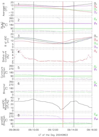
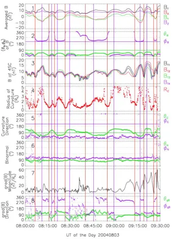
Fig. 3a. The geometric structure of the tilted current sheet during one Cluster crossing event on 3 August 2004. The format of the figure is
the same as Fig. 1a.
Panels 1–3 of Fig. 3a show the magnetic field in this cur-rent sheet. At the center of the curcur-rent sheet, the magnetic field points northward and has a minimum value. Panels 4–6 of Fig. 3a show the configuration of magnetic field lines in this current sheet. As seen from panel 4 of Fig. 3a, the curva-ture radius of the MFLs in the neutral sheet is rather larger, around 2RE. Panel 6 shows that the curvature points earth-ward, and that the binormal of the MFLs in the CS is more or less constant with a direction of (θN,ϕN)≈(83◦, 114◦), indi-cating the MFLs in the current sheet are plane curves about
vertical to the equatorial plane. Panels 7–8 of Fig. 3a give the features of the gradient of the magnetic strength, ∇B, which has a minimum value in the center of the CS, and reaches maximum values at the boundaries of the NS. The direction of∇Bpoints towards dawnside at the northern side (Bx>0)and duskside at the southern side (Bx<0)and it re-verses its direction at the center of the CS. The direction an-gles (θgB,ϕgB) of∇Bare (88.2◦, 296◦)at the northern side and (87.4◦, 125◦)at the southern side, yielding the normalnˆ
[image:7.595.128.470.60.533.2]3532 C. Shen et al.: Tail tilted current sheets
20
Figure 3b The geometric structure of the tilted current sheet during one Cluster crossing event on 3 Aug 2004. The format of the
[image:8.595.134.464.60.526.2]figure is the same as Fig. 1b.
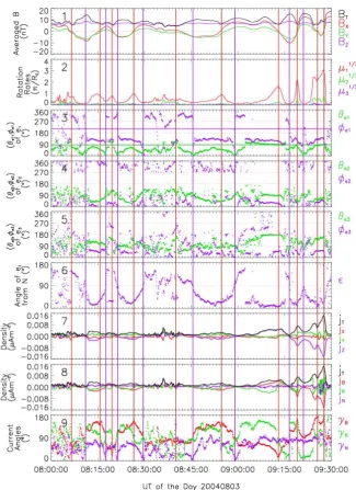
Fig. 3b. The geometric structure of the tilted current sheet during one Cluster crossing event on 3 August 2004. The format of the figure is
the same as Fig. 1b.
the CS/NS is duskward and almost parallel to the binormal
ˆ
N of the MFLs. This CS is therefore nearly vertical to the equatorial plane, as demonstrated in Fig. 4.
Panels 2–5 of Fig. 3b illustrate the properties of the mag-netic rotation in this current sheet event on 3 August 2004. The maximum magnetic rotation rate of the magnetic field vector µ11/2 is much larger than the medium rotation rate µ12/2, while the minimum rotation rateµ13/2 is nearly zero. Thus, this is a 1-D current sheet. The peak of the max-imum magnetic rotation rateµ11/2 appears at the center of
the neutral sheet, so the magnetic field vector rotates fastest at the center of the neutral sheet. The direction of e(1) is constant in the NS and is about (89◦, 115◦)at the center. Thus, the normal nˆ of the CS/NS is (89.5◦, 117◦), which
C. Shen et al.: Tail tilted current sheets 3533
21
Fig. 4 Schematic illustration of the geometrical structure of the severely tilted
current sheet during the Cluster crossing event on 3 Aug 2004 viewed toward the
earth. The dashed line denotes the central plane of the current sheet. The red arrow
represents the current density. The directions of the magnetic field in the MFLs have
been marked in the figure. Several geometrical parameters of the current sheet are
shown. zˆGSM and ϕˆGSM are the base vectors along the z axis and azimuthal
directions in GSM coordinates, respectively.
Fig. 4. Schematic illustration of the geometrical structure of the
severely tilted current sheet during the Cluster crossing event on 3 August 2004 viewed toward the earth. The dashed line denotes the central plane of the current sheet. The red arrow represents the current density. The directions of the magnetic field in the MFLs have been marked in the figure. Several geometrical parameters of the current sheet are shown. zˆGSMandϕˆGSMare the base vectors along the z axis and azimuthal directions in GSM coordinates, re-spectively.
same as that determined from Eq. (2). The angle ε be-tweene(1)and the binormalNˆ is very small, and is approx-imately 6.7◦ at the center of NS (panel 6). Therefore, the tilt angle of the current sheet can be yielded from Eq. (4) as δ≈ |90◦−ε| ≈83.3◦.
[image:9.595.313.538.61.457.2]Panels 7–9 of Fig. 3b show the distribution of the cur-rent density in the curcur-rent sheet. As illustrated in panel 7 of Fig. 3b, the northern componentjzis positive and occupies nearly all the current density, so that the current in the cur-rent sheet is almost northward or in the Z direction, further indicating that this current sheet is vertical to the equatorial plane. Similar to the first tilted current sheet on 5 August 2001 investigated above, the current density has one bifur-cated profile (Runov et al., 2003; Zelenyi et al., 2004; Asano et al., 2005; Nakamura et al., 2006; Thompson et al., 2006), the current density maximizes at the two boundaries of the NS and minimizes at the center of the neutral sheet. And also the two humps of the current density overlap the two peaks of the gradient of the magnetic strength. At the center of the neutral sheet, the current becomes almost field-aligned (panel 8), and the angleγBof the current from the magnetic field is about 16◦at the center of the NS (panel 9). The angle γNof the current from the binormalNˆ remains constant and is approximately 75◦at the center of the NS.
The parameters of this tilted current sheet are listed in Ta-ble 1. Figure 4 shows the demonstration of the geometrical structure of the tilted current sheet during the Cluster
cross-ing event at 09:08–09:16 UT on 3 August 2004. In short, this 23
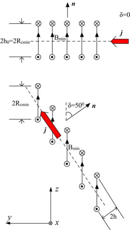
We may check the relationship between the thickness of the NS and the tilt angle
for one of these tilted current sheets. A Harris type current sheet with no guiding field
By is shown in the upper panel in Fig 5. If the neighboring MFLs are slipping from
each other while the configuration and orientation of the MFLs remain unchanged
(see the lower panel in Fig. 5), the magnetic field (including its strength and direction)
at any fixed point of one MFL will not vary, so that the two boundaries of the NS will
not change their locations at the MFLs of the current sheet.
Fig. 5 The transformation from the normal Harris type current sheet (upper panel)
to the tilted current sheet (lower panel) through the slipping of the MFLs.
Therefore the thickness of the NS (that is the distance between the two
boundaries of the NS) in the tilted current sheet is
2
h
≈
2
h
0cos
δ
. (6)
For the Harris type current sheet with no guiding field By, the half-thickness
h
0of
Fig. 5. The transformation from the normal Harris type current
sheet (upper panel) to the tilted current sheet (lower panel) through the slipping of the MFLs.
current sheet is a vertical current sheet with a tilted angle of about 75◦. The current in this tilted CS flows almost along Z direction and has a large field-aligned component at the cen-ter of its NS. Its normal is duskward at a direction of about (89.6◦, 111◦).
[image:9.595.51.286.66.236.2]3534 C. Shen et al.: Tail tilted current sheets
24
the NS is equal to the minimum radius of curvature, Rc,min, of MFLs in the current sheet, i.e., h0=Rc,min(see Appendix A in Shen et al., 2007a). So that
h≈Rcmincosδ. (7)
The above formula relates the half-thickness h of the NS to the minimum radius of curvature, Rc,min, of MFLs and the tilt angle δ of the current sheet. The parameters for the two events in Table 1 satisfy this formula well. Eq. (7) implies that the larger the tilt angle of the current sheet, the thinner its NS and the larger the current density in the neutral sheet (Eq. (3)). Runov et al. (2005a) have argued that the thickness of the current sheet has no relationship with the minimum radius of curvature of MFLs because they have not included this influence of the tilt angle.
2.2 Flapping Motion Propagation of the Tail Current Sheet
In Section 2.1, the features of the tail tilted current sheet have been investigated by analyzing Cluster 4 point magnetic observations. Typically, the tilted current sheet is closely related to the flapping motion of the tail current sheet. Here we may explore the properties of the tail current sheet flapping motion and its possible origin.
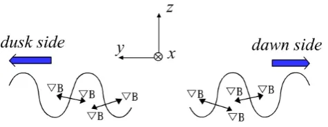
Fig.6 Illustration of the propagation of the flapping waves of the tail tilted current sheet
Here, by determining propagation directions based on the magnetic gradient, we may try a new perspective, so that one can determine the propagation direction of current sheet flapping waves easily and intuitively. (Obviously, the timing analysis
Fig. 6. Illustration of the propagation of the flapping waves of the
tail tilted current sheet.
Therefore the thickness of the NS (that is the distance be-tween the two boundaries of the NS) in the tilted current sheet is
2h≈2h0cosδ. (6)
For the Harris type current sheet with no guiding field By, the half-thicknessh0of the NS is equal to the minimum
ra-dius of curvature,Rc,min, of MFLs in the current sheet, i.e.,
h0=Rc,min(see Appendix A in Shen et al., 2007a). So that
h≈Rc,mincosδ. (7)
The above formula relates the half-thicknesshof the NS to the minimum radius of curvature,Rc,min, of MFLs and the
tilt angleδof the current sheet. The parameters for the two events in Table 1 satisfy this formula well. Equation (7) im-plies that the larger the tilt angle of the current sheet, the thinner its NS and the larger the current density in the neu-tral sheet (Eq. 3). Runov et al. (2005a) have argued that the thickness of the current sheet has no relationship with the minimum radius of curvature of MFLs because they have not included this influence of the tilt angle.
2.2 Flapping motion propagation of the tail current sheet In Sect. 2.1, the features of the tail tilted current sheet have been investigated by analyzing Cluster 4 point magnetic ob-servations. Typically, the tilted current sheet is closely re-lated to the flapping motion of the tail current sheet. Here we may explore the properties of the tail current sheet flapping motion and its possible origin.
Here, by determining propagation directions based on the magnetic gradient, we may try a new perspective, so that one can determine the propagation direction of current sheet flapping waves easily and intuitively. (Obviously, the timing analysis (Russell et al., 1983; Harvey, 1998; Schwartz, 1998; Dunlop and Woodward, 1998; Sonnerup et al., 2008) can also be used to analyse the propagation direction and velocity of the current sheet flapping.) Figure 6 shows the sketched flapping waves of the tail current sheet, assumed to propa-gate towards flanks in the pmidnight or post-midnight re-gion. Generally, in the tail current sheet, the gradient of the magnetic strength∇Bpoints outward from the center of the current sheet. The measured∇B will reverse its direction
when one current sheet crosses the spacecraft. When the flap-ping waves propagate towards the dawnside (duskside),∇B measured by the S/C will points first dawnward (duskward) with its azimuthal angleϕgB near to 270◦ (90◦), and then duskward (dawnward) with its azimuthal angleϕgB near to 90◦(270◦). Therefore, the propagation directions of the flap-ping motion of the tail current sheet can be determined vi-sually from the variation of the directional angle of∇B, as demonstrated in Fig. 6.
The second event introduced above in fact has a larger in-terval of interest in this regard. During 06:30–09:30 UT on 3 August 2004, Cluster observed one tail current sheet flapping event, which has also been studied previously by Petrukovich et al. (2006). When this CS flapping event occurs, Cluster is at 19REgeocentric distance, and its position angles in GSM coordinates are (θ,ϕ)=(84◦, 211◦)with a local time of 2.1 h.
Cluster is 9.64RE away from the midnight meridian plane at the dawnside tail. The average Cluster tetrahedron size is approximately 890 km. Cluster is in fact situated close to apogee and hardly moves at all in GSM in the three hours indicated.
Figure 7a and b demonstrates the variations of the vari-ous parameters of the magnetic field as Cluster crosses the CS periodically during this flapping event, in which the cen-ters of the NS are marked by red vertical lines. Each time Cluster crosses the center of the NS, the magnetic strength drops to the minimum and the Bx changes its sign (panel 1 of Fig. 7a). The polar angleθBbecomes very small (panel 2 of Fig. 7a), implying the magnetic field is nearly northward there. The curvature radius of the MFLs minimizes (panel 4 of Fig. 7a) and the gradient of the magnetic strength has the lowest value (panel 7 of Fig. 7a) and reverses its direction (panel 8 of Fig. 7a). The magnetic rotation rates peak at the center of the NS (panel 2 of Fig. 7b) and the current density has very significant Z componentjzand field-aligned com-ponentjB. The parameters at the center of the NS during these series of CS crossing events are listed in Table 2. As shown in panel 6 of Fig. 7a, during this CS flapping event, the binormalNˆ of the MFLs is nearly constant and is about (80◦, 120◦)on average. The normalnˆ of the NS, as deter-mined by the first eigenvectoreˆ(1)in Table 2, deviated con-siderably from the northern direction, and generally leans to the flank sides. Therefore, from the features of the NS de-duced here, we may believe that the current sheet is tilted as its NS crosses Cluster and that the tail current sheet is flap-ping. The various parameters for each tilted current sheet at the Cluster crossing times are listed in Table 2. It is noted that the half thicknesshof the NS, the tilt angleδ and the minimum radius of curvature,Rc,min, of MFLs in the current
sheet, as shown in Table 2, basically obey the relationship h≈Rc,mincosδ(Eq. 7). With temporal evolution of the
[image:10.595.50.288.61.153.2]C. Shen et al.: Tail tilted current sheets 3535
28
Figure 7a The geometric structure of the tilted current sheet during a series of Cluster crossings on 3 Aug 2004. The format of the figure is just same as that of Fig. 1a.
Fig. 7a. The geometric structure of the tilted current sheet during a series of Cluster crossings on 3 August 2004. The format of the figure is
just same as that of Fig. 1a.
current sheet becomes a very-nearly vertical sheet. These features manifest the gradually growing of the tail flapping motion during 08:00–09:30 UT.
Between the neighboring NS crossing events, Cluster lies at regions where the current sheet becomes a normal one, as marked by violet vertical lines in Fig. 7a and b. During these special periods, the flapping wave motion is sampled at its wave crests or wave troughs. At these times, the first eigenvectoreˆ(1)(panel 3 of Fig. 7b), may be regarded as the normalnˆ of the NS and is about northward. The angleεis about 90◦(panel 6 of Fig. 7b), thus the tilt angleδ is nearly
0◦and the current density is almost totally duskward (panel 7
[image:11.595.128.468.58.531.2]3536 C. Shen et al.: Tail tilted current sheets
29
Figure 7b The geometric structure of the tilted current sheet during a series of Cluster crossings on 3 Aug 2004. The format of the figure is the same as Fig. 1b.
Fig. 7b. The geometric structure of the tilted current sheet during a series of Cluster crossings on 3 August 2004. The format of the figure is
the same as Fig. 1b.
of the NS is hVni ≈27 Km/s. Thus, the phase velocity of the flapping waves ishVPi ≈ hVni/sinhδi ≈29 Km/s. The averaged period of the flapping waves ishTi ≈14 min s, so the expected wavelength ishλi ≈ hVPi · hTi ≈3.8RE. Based on the above analysis, we may give a demonstration of the structure of ideal tail current sheet flapping waves propagat-ing dawnward as in Fig. 8.
In order to make clear the features of the tail current sheet flapping waves, we need to investigate more events. Table 3 shows the deduced features of the six important tail current sheet flapping events from our methods (some physical pa-rameters are not available for the event on 26 September
[image:12.595.137.463.59.507.2]C. Shen et al.: Tail tilted current sheets 3537
Table 2. The parameters of the magnetic field at the center of the neutral sheet during the series of CS crossing events on 3 August 2004.
Time Rc,min eˆ(1)(nˆ) bˆ µ11 max/2 j γB γN δ≈
90◦−ε
Nˆ h Vn
(RE) (θe1,ϕe1) (θB,ϕB) (π/RE) (µA/m2) (θN,ϕN) (RE) (km/s)
08:06:30 0.83 (64◦, 306◦) (16◦, 253◦) 0.69 0.0016 39◦ 53◦ 54◦ (80◦, 126◦) 0.46 31 08:15:40 0.74 (48◦, 116◦) (11◦, 322◦) 0.80 0.0022 144◦ 56◦ 57◦ (80◦, 127◦) 0.40 13 08:19:30 0.88 (106◦, 129◦) (12◦, 307◦) 0.80 0.0017 26◦ 68◦ 63◦ (79◦, 125◦) 0.40 27 08:26:30 0.69 (55◦, 115◦) (6.9◦, 288◦) 0.95 0.0019 161◦ 78◦ 61◦ (84◦, 126◦) 0.34 19 08:40:00 1.4 (104◦, 115◦) (20◦, 304◦) 0.39 0.00067 77◦ 154◦ 54◦ (71◦, 105◦) 0.82 49 08:54:40 0.97 (49◦, 125◦) (20◦, 293◦) 0.88 0.0025 140◦ 64◦ 67◦ (70◦, 122◦) 0.36 24 09:13:00 1.8 (89◦, 115◦) (8.7◦, 269◦) 1.6 0.0047 16◦ 75◦ 83.3◦ (82◦, 114◦) 0.20 9.2 09:19:00 1.3 (79◦, 125◦) (12◦, 267◦) 2.1 0.0068 162◦ 81◦ 80◦ (81◦, 116◦) 0.15 40 09:25:15 0.96 (82◦, 127◦) (2.1◦, 298◦) 2.2 0.0062 172◦ 86◦ 75◦ (88◦, 114◦) 0.14 17 09:27:40 0.77 (83◦, 113◦) (12◦, 280◦) 2.8 0.014 169◦ 87◦ 78◦ (85◦, 123◦) 0.11 17
Figure 8 Schematic illustration of the ideal flapping waves moving dawnward in the tail
In order to make clear the features of the tail current sheet flapping waves, we need to investigate more events. Table 3 shows the deduced features of the six important tail current sheet flapping events from our methods (some physical parameters are not available for the event on 26 Sep 2001 because Cluster is outside of the neutral sheet), which have also been investigated in the literature (Sergeev et al., 2003, 2004; Runov et al. 2005a, 2005b; Zhang et al., 2002, 2005; Petrukovich et al.2006). The locations of all these events are about 10RE away from the midnight
meridian and much nearer to the dawnside or duskside flanks. For these tail flapping events, the minimum curvature radius of the MFLs in the current sheet is rather large, with typical values of 0.32~1.5RE, while the neutral sheet, as Cluster crosses, is very
thin, with the averaged half thickness being about 0.14~0.36RE.This is caused by the
slipping of the MFLs and governed approximately by the formula (7). While the flapping waves are passing by Cluster, the current sheet is tilted severely, with the tilt angle being about 65º~75º. The phase velocities of these flapping waves are
approximately 22~72Km/s, while their periods and wavelengths are about 10~32min
and 3.8~8.1RE, respectively. As pointed out by other researchers (Sergeev et al.2003,
2004; Runov et al. 2005a, 2005b; Zhang et al., 2002, 2005; Petrukovich et al.2006), the flapping waves tend to propagate outward from the midnight meridian, i.e., the
Fig. 8. Schematic illustration of the ideal flapping waves moving dawnward in the tail.
flapping waves are passing by Cluster, the current sheet is tilted severely, with the tilt angle being about 65◦∼75◦. The phase velocities of these flapping waves are approximately 22∼72 Km/s, while their periods and wavelengths are about 10∼32 min and 3.8∼8.1RE, respectively. As pointed out by other researchers (Sergeev et al., 2003, 2004; Runov et al., 2005a, b; Zhang et al., 2002, 2005; Petrukovich et al., 2006), the flapping waves tend to propagate outward from the mid-night meridian, i.e., the flapping waves move dawnward at the dawn side and duskward at the dusk side. The flapping motions usually last several hours, as shown in Table 3, indi-cating that there is a continuous and stable energy supply.
With Cluster and DSP (Liu et al., 2005) conjunction tail observations, Zhang et al. (2005) have found that the spa-tial scale of the flapping motions along the tail direction is larger than 5RE and they may occur at tailward distance of
11∼30RE. Previous analysis (Sergeev et al., 2003, 2004, 2006; Zhang et al., 2002, 2005) has argued that the sources of the flapping motion of tail current sheet is at the tail mid-night meridian, possibly caused by bursty bulk flows (BBF) (Angelopoulos et al., 1994) during local energy transient dis-sipations (Sergeev et al., 1996). However, the transient en-ergy release events in the near-earth midnight plasma sheet generally have a spatial scale of severalRE, and temporal scale of several minutes (Sergeev et al., 1996), while the tail flapping motions span a rather large part of the magnetotail (maybe the whole near earth magnetotail), lasting about sev-eral hours gensev-erally. And one fact is that during the six tail CS flapping events listed in Table 3, the magnetosphere is quiet or only has weak activities in general (see Table 3). Therefore, it is doubtful if the local transient energy release events in the near-earth midnight plasma sheet are able to
3538 C. Shen et al.: Tail tilted current sheets
Fig. 9 The solar wind conditions as observed by the ACE spacecraft and the physical quantities of the tail current sheet measured by Cluster during the tail flapping event on 3 Aug 2001. Cluster is at 19Re geocentric distance, at the nightside equatorial plane, and
its polar angle
θ
and azimuthal angleϕ
in GSM are about 81º and 207º, respectively. Panel 1: the interplanetary magnetic field(IMF) in GSE; Panel 2: The velocity of the solar wind; Panel 3: the dynamic pressure of the solar wind; Panel 4: the magnetic field at
the center of Cluster tetrahedron as are the average of those at the four S/C in GSM; panel 5: the directional angle (
θ
B,ϕ
B) of themagnetic field at the center of Cluster tetrahedron in GSM; panel 6: The three components (
j
x,j
y,j
z) of the current density at the [image:14.595.137.466.61.512.2]center of Cluster tetrahedron at GSM coordinates. In Panel 4-6, the data before UT08:10 are pseudo due to the unavailability of actual observation data.
Fig. 9. The solar wind conditions as observed by the ACE spacecraft and the physical quantities of the tail current sheet measured by Cluster
during the tail flapping event on 3 August 2001. Cluster is at 19RE geocentric distance, at the nightside equatorial plane, and its polar
angleθ and azimuthal angleϕin GSM are about 81◦ and 207◦, respectively. Panel 1: the interplanetary magnetic field (IMF) in GSE; panel 2: The velocity of the solar wind; panel 3: the dynamic pressure of the solar wind; panel 4: the magnetic field at the center of Cluster tetrahedron as are the average of those at the four S/C in GSM; panel 5: the directional angle (θB,ϕB) of the magnetic field at the center of
Cluster tetrahedron in GSM; panel 6: The three components (jx,jy,jz) of the current density at the center of Cluster tetrahedron at GSM
coordinates. In panels 4–6, the data before 08:10 UT are pseudo due to the unavailability of actual observation data.
supply the energy for sustaining the tail flapping motions with large temporal and spatial scales.
Based on the facts revealed here, we would suggest that the tail current sheet flapping motion is possibly the manifesta-tion of the global oscillating momanifesta-tion of the tail caused by the interaction between the tail and the solar wind, the energy for which is provided by the solar wind. Figure 9 illustrates the
C. Shen et al.: Tail tilted current sheets 3539
35
Fig. 10 The solar wind conditions as observed by ACE spacecraft and physical quantities of the tail current sheet measured by
Cluster during the tail flapping event on 5 Aug 2001. Cluster is at 19.3Re geocentric distance, at the nightside equatorial plane, and its
polar angle
θ
and azimuthal angleϕ
in GSM are about 85º and 206º, respectively. The format of the figure is just same as that of [image:15.595.137.464.61.509.2]Fig. 11. In Panel 4-6, the data before UT12:00 are pseudo due to the unavailability of actual observation data.
Fig. 10. The solar wind conditions as observed by ACE spacecraft and physical quantities of the tail current sheet measured by Cluster during
the tail flapping event on 5 August 2001. Cluster is at 19.3REgeocentric distance, at the nightside equatorial plane, and its polar angleθ
and azimuthal angleϕin GSM are about 85◦and 206◦, respectively. The format of the figure is just same as that of Fig. 11. In panel 4–6, the data before 12:00 UT are pseudo due to the unavailability of actual observation data.
the tail current sheet flapping motion on 3 August 2001 is possibly created by interaction between the magnetosphere and the solar wind with fast velocity and high dynamic pres-sure. Figure 10 demonstrates that another tail current sheet flapping event occurring on 5 August 2001. From Fig. 10 we may see that the tail flapping motion takes place dur-ing the solar wind velocity enhancement period. The current sheet flapping motion during 13:00–15:40 UT occurs within the interval of the recovery phase of a strong substorm; while the current sheet flapping motion during 15:40–18:00 UT ap-pears when the magnetosphere is quiet. So that, the
enhance-ment of the solar wind velocity is possibly the cause gener-ating this tail flapping wave motion on 5 August 2001.
3540 C. Shen et al.: Tail tilted current sheets
36
Fig. 11 Demonstration of the flapping motion of the near earth tail caused by the impact of disturbed solar wind.
[image:16.595.103.496.64.207.2]Fig. 11. Demonstration of the flapping motion of the near earth tail caused by the impact of disturbed solar wind.
Table 3. Parameters of tail CS flapping events.
Events R (θ,ϕ) LT Y in GSM hBmini Rc,min hhi hδi hVni hVPi hTi hλi Lifetime Propagation Magnetospheric (RE) in GSM (h) (RE) (nT) (RE) (RE) (Km/s) (Km/s) (min s) (RE) direction activities
3 Aug 2001, 19 (81◦, 207◦) 1.8 −8.5 13 1.5 0.36 75◦ 21 22 32 6.6 2 h dawnward Later recovery 08:30–10:30 UT
5 Aug 2001, 19.3 (85◦, 206◦) 1.7 −8.4 12.0 0.6 0.24 58◦ 61 72 12 8.1 5 h dawnward 13:00–15:40 UT: Strong;
13:00–18:00 UT 15:40–18:00 UT: quiet
26 Sep 2001, 19.3 (91◦, 158◦) 22.5 7.2 >1 h duskward weak
22:15–>23:20 UT
20 Oct 2001, 18 (94◦, 138◦) 20.8 12 2.8 0.32 0.14 65◦ 40 44 10 4.2 0.5 h duskward quiet 09:30–10:00 UT
3 Aug 2004, 19 (84◦, 211◦) 2.1 −9.8 6.3 1.0 0.28 67◦ 27 29 14 3.8 3 h dawnward quiet
06:30–09:30 UT
5 Aug 2004, 18.5 (82◦, 210◦) 2.0 −9.2 6.2 0.95 0.28 65◦ 31 34 17.5 5.6 5hrs dawnward weak
13:00–18:00 UT
3 Summary and conclusions
Tilted current sheets and current sheet flapping waves in the Earth’s magnetotail are frequently occurring phenom-ena which have drawn much recent attention. The purpose of this paper is to clearly understand the geometrical struc-ture of the tail tilted current sheet and current sheet flap-ping waves based on Cluster (Escoubet et al., 2001) multi-ple spacecraft measurements. To achieve this goal, previ-ously developed multi-point data analysis methods (Shen et al., 2003, 2007a, b), i.e. curvature analysis and magnetic ro-tation analysis (MRA), are applied in this research. By using the previously developed multiple point data analysis meth-ods (Shen et al., 2003, 2007a, b, 2008), we have investigated the geometrical structures of tilted current sheet and tail flap-ping waves. The configurations of the tilted current sheet have been directly and clearly revealed for the first time, as illustrated in Figs. 2, 4 and 5. As in previous investigations (Shen et al., 2007a), the neutral sheet (NS) is defined as the region within whichB≤
√
2Bminin the current sheet. The
magnetic field vector rotates about 90◦ in the NS (Shen et al., 2008b), so the NS is actually the magnetic vector rota-tion layer in the current sheet. We have given the explicit and
quantitative definition of the tilt angle of the tilted current sheet for the first time: the tilt angleδ of the tilted current sheet as the complementary angle of the angle between the normalnˆ of the CS and the binormalNˆof the MFLs in the NS.
We summarize the common features of the tilted current sheet as follows:
1. The MFLs of the tilted CS are plane curves similar that of the normal CS except that the neighboring MFLs slip relative to each other in the plane of curvature. The os-culating planes of the MFLs in the tilted CS are approx-imately vertical to the equatorial plane, and the binor-mals of the MFLs are generally along the dawn-dusk direction. However, the normal of the tilted CS deviates from the south-north (Z) direction and leans to the flank sides.
C. Shen et al.: Tail tilted current sheets 3541 relationshiph≈Rc,mincosδ. In general, the more tilted
the current sheet, the thinner the NS.
3. In the NS of the tilted current sheet, the field-aligned current component is very large, has a one-peak profile and maximizes at the center of the CS.
4. The larger the tilt-angle of the tilted CS, the stronger the current density in its NS. In some of the tilted CS cases, the current density profile may have a bifurcated profile. The current density maximizes near the two boundaries of the NS and minimizes at the center of the neutral sheet, the two humps of the current density of-ten superpose the two peaks of the gradient of magnetic strength. This may indicate the significant contribution of the magnetic gradient drift current.
The tilted current sheet typically appears along with the oc-currence of tail current sheet flapping waves. Six current sheet flapping motion events have been analyzed in this re-search. It is found that, for these tail flapping events, the min-imum radius of the curvature of the MFLs in the current sheet is about 0.32∼1.5RE on average, while the averaged half thickness of the neutral sheet is only about 0.14∼0.36RE. During these tail flapping motion as measured by Cluster, the current sheet is tilted severely, its tilt angle may be about 65◦∼75◦in average. The phase velocities of these flapping waves are approximately 22∼72 Km/s, and the wavelengths are about 3.5∼8.1RE. The lifetime of one tail flapping mo-tion is about several hours. The tail flapping waves generally occur during quiet or weak activity periods. The locations of the observed tail flapping motions are about ten earth radii far away from the midnight meridian. These observations have shown that the tail flapping motions are large scale and long-lasting global processes, which may possibly be caused by the interaction between the solar wind and the magneto-sphere when there are enhancements of the velocity or/and the dynamic pressure of the solar wind. The actual mecha-nism of the tail flapping waves and the source of their energy are still unclear. More observational and theoretical work is needed for a fuller understanding of the generation and evolution of tail flapping waves, and their roles on magneto-spheric processes.
Acknowledgements. This work was supported by the National Natural Science Foundation of China Grant No. 40674094, and 40523006, Ministry of Science and Technology of China Grant 2006CB806305, the Hundred Talents Program of the CAS, Interna-tional Space Science Institute at Bern, and the Specialized Research Fund for State Key Laboratories. The authors are grateful to Cluster FGM team, the Hungarian Data Centre and the ACE Science Cen-ter for providing us with four satellite magnetic measurement data, Cluster position data, and ACE level 2 data, respectively.
Topical Editor R. Nakamura thanks two anonymous referees for their help in evaluating this paper.
References
Angelopoulos, V., Kennel, C., Coroniti, F., Pellat, R., Kivelson, M., Walker, R., Russell, C., Baumjohann, W., Feldman, W., and Gosling, J.: Statistical Characteristics of Bursty Bulk Flow Events, J. Geophys. Res., 99, 21 257–21 280, 1994.
Asano, Y., Nakamura. R., Baumjohann, W., Runov, A., V¨or¨os, Z., Volwerk, M., Zhang, T. L., Balogh, A., Klecker, B., and H. R`eme: How typical are atypical current sheets?, Geophys. Res. Lett., 32, L03108, doi:10.1029/2004GL021834, 2005.
Balogh, A., Carr, C. M., Acu˜na, M. H., et al.: The Cluster magnetic field investigation: overview of in-flight performance and initial results, Ann. Geophys., 19, 1207–1217, 2001,
http://www.ann-geophys.net/19/1207/2001/.
Chanteur, G.: Spatial Interpolation for four spacecraft: Theory, in: Analysis Methods for Multi-Spacecraft Data, edited by: Paschmann, G. and Daly, P. W., p. 349, ESA Publications Di-vision, Noordwijk, The Netherlands, 1998.
Dunlop, M. W., Balogh, A., Glassmeier, K.-H., and Robert, P.: Four-point Cluster application of magnetic field analy-sis tools: The Curlometer, J. Geophys. Res., 107, 1384, doi:10.1029/2001JA005088, 2002.
Dunlop, M. W. and Woodward, T. I.: Multi-spacecraft discontinu-ity analysis: Orientation and motion, in: Analysis Methods for Multi-Spacecraft Data, edited by: Paschmann, G. and Daly, P. W., p. 271, ESA Publ. Div., Noordwijk, Netherlands, 1998. Erkaev, N. V., Semenov, V. S., and Biernat, H. K.: Magnetic double
gradient mechanism for flapping oscillations of a current sheet, Geophys. Res. Lett., 35, L02111, doi:10.1029/2007GL032277, 2008.
Escoubet, C. P., Fehringer, M., and Goldstein, M.: The Cluster mis-sion, Ann. Geophys., 19, 1197–1200, 2001,
http://www.ann-geophys.net/19/1197/2001/.
Fairfield, D. H.: A statistical determination of the shape and the position of the geomagnetic neutral sheet, J. Geophys. Res., 85, 775–780, 1980.
Fairfield, D. H., Hones, E. W., and Meng, C. I.: Multiple crossing of a very thin plasma sheet in the Earth’s magnetotail, J. Geophys. Res., 86, 11 189–11 200, 1981.
Golovchanskaya, I. V. and Maltsev, Y. P.: On the identification of plasma sheet flapping waves observed by Cluster, J. Geophys. Res., 32, L02102, doi:10.1029/2004GL021552, 2005.
Harris, E. G.: On a plasma sheet separating regions of oppositely directed magnetic field, Nuovo Cimento, 23, 115–121, 1962. Harvey, C. C.: Spatial gradients and the volumetric tensor, in:
Anal-ysis Methods for Multi-Spacecraft Data, edited by: Paschmann, G. and Daly, P. W., p. 307, ESA Publications Division, Noord-wijk, The Netherlands, 1998.
Kaymaz, Z., Siscoe, G., Luhmann, J. G., Fedder, J. A., and Lyon, J. G.: Interplanetary Magnetic Field Control of Magnetotail Field: IMP 8 Data and MHD Model Compared, J. Geophys. Res., 100, 17 163–17 172, 1995.
Liu, Z. X., Escoubet, C. P., Pu, Z., Laakso, H., Shi, J. Q., Shen, C., and Hapgood, M.: The Double Star Mission, Ann. Geophys., 23, 2707–2712, 2005, http://www.ann-geophys.net/23/2707/2005/. Lui, A. T. Y., Meng, C.-I., and Akasofu, S.-I.: Wavy nature of
the magnetotail neutral sheet, Geophys. Res. Lett., 5, 279–282, 1978.
3542 C. Shen et al.: Tail tilted current sheets
Monograph, 28, 158–170, 1984.
Lui, A. T. Y.: Potential plasma instabilities for substorm expansion onsets, Space Sci. Rev., 113, 127–206, 2004.
Malova, H. V., Zelenyi, L. M., Popov, V. Y., Delcourt, D. C., Petrukovich, A. A., and Runov, A. V.: Asymmetric thin cur-rent sheets in the Earth’s magnetotail, Geophys. Res. Lett., 34, L16108, doi:10.1029/2007GL030011, 2007.
McComas, D. J., Russell, C. T., Elphic, R. C., and Bame, S. J.: The Near-Earth Cross-Tail Current Sheet: Detailed ISEE1 and 2 Case Studies, Geophys. Res., 91, 4287–4301, 1986.
Nakamura, R., Baumjohann, W., Runov, A., and Asano, Y.: Thin Current Sheets in the Magnetotail Observed by Cluster, Space Sci. Rev., 122, 29–38, 2006.
Nakagawa, T. and Nishida, A.: Southward magnetic field in the neu-tral sheet produced by wavy motions in the dawn-dusk direction, Geophys. Res. Lett., 11, 1265–1268, 1989.
Ness, N. F.: The Earth’s magnetic tail, J. Geophys. Res., 70, 2989– 3005, 1965.
Petrukovich, A. A., Baumjohann, W., Nakamura, R., Runov, A., and Balogh, A.: Cluster vision of the magnetotail cur-rent sheet on a macroscale, J. Geophys. Res., 110, A06204, doi:10.1029/2004JA010825, 2005.
Petrukovich, A. A., Zhang, T. L., Baumjohann, W., Nakamura, R., Runov, A., Balogh, A., and Carr, C.: Oscillations of flux tube slippage in the quiet plasma sheet, Ann. Geophys., 24, 1695– 1704, 2006, http://www.ann-geophys.net/24/1695/2006/. Runov, A., Nakamura, R., Baumjohann, W., Zhang, T. L., Volwerk,
M., Eichelberger, H. U., and Balogh, A.: Cluster observation of a bifurcated current sheet, Geophys. Res. Lett., 30(2), 1036, doi:10.1029/2002GL016136, 2003.
Runov, A., Sergeev, V. A., Baumjohann, W., Nakamura, R., Ap-atenkov, S., Asano, Y., Volwerk, M., V¨or¨os, Z., Zhang, T. L., Petrukovich, A., Balogh, A., Sauvaud, J. A., Klecker, B., and R`eme, H.: Electric current and magnetic field geometry in flap-ping magnetotail current sheets, Ann. Geophys., 23, 1391–1403, 2005a, http://www.ann-geophys.net/23/1391/2005/.
Runov, A., Sergeev, V. A., Nakamura, R., Baumjohann, W., Zhang, T. L., Asano, Y., Volwerk, M., V¨or¨os, Z., Balogh, A., Sauvaud, J.-A., and R`eme, H.: Reconstruction of the magnetotail current sheet structure using multi-point Cluster measurements, Planet. Space Sci., 53, 237–243, 2005b.
Runov, A., Sergeev, V. A., Nakamura, R., Baumjohann, W., Ap-atenkov, S., Asano, Y., Takada, T., Volwerk, M., V¨or¨os, Z., Zhang, T. L., Sauvaud, J.-A., R`eme, H., and Balogh, A.: Local structure of the magnetotail current sheet: 2001 Cluster observa-tions, Ann. Geophys., 24, 247–262, 2006,
http://www.ann-geophys.net/24/247/2006/.
Russell, C. T., Mellott, M. M., Smith, E. J., and King, J. H.: Multiple spacecraft observations of interplanetary shocks: Four spacecraft determination of shock normals, J. Geophys. Res., 88, 4739–4748, 1983.
Schwartz, S. J.: Shock and discontinuity normals, Mach num-bers, and related parameters, in: Analysis Methods for Multi-Spacecraft Data, edited by: Paschmann, G. and Daly, P. W., p. 249, ESA Publ. Div., Noordwijk, Netherlands, 1998.
Sergeev, V. A., Mitchell, D. G., Russell, C. T., and Williams, D. J.: Structure of the tail plasma/current sheet at 11 Re and its changes in the course of a substorm, J. Geophys. Res., 98, 17 345–17 365, 1993.
Sergeev, V. A., Pulkkinen, T., and Pellinen, R.: Coupled-mode scenario for the magnetospheric dynamics, J. Geophys. Res., 101(A6), 13 047–13 065, 1996.
Sergeev, V. A., Runov A., Baumjohann,W., Nakamura, R., Zhang, T. L., Volwerk,M., Balogh, A., R`eme, H., Sauvaud, J. A., Andr`e, M., and Klecker, B.: Current sheet flapping motion and structure observed by Cluster, Geophys. Res. Lett., 30, 1327, doi:10.1029/2002GL016500, 2003.
Sergeev, V. A., Runov, A., Baumjohann,W., Nakamura, R., Zhang, T. L., Balogh, A., Louarn, P., Sauvaud, J.-A., and R`eme, H.: Ori-entation and propagation of current sheet oscillations, Geophys. Res. Lett., 31, L05807, doi: 10.1029/2003GL019346, 2004. Sergeev, V. A., Sormakov, D. A., Apatenkov, S. V., Baumjohann,
W., Nakamura, R., Runov, A., Mukai, T., and Nagai, T.: Survey of large-amplitude flapping motions in the midtail current sheet, Ann. Geophys., 24, 2015–2024, 2006,
http://www.ann-geophys.net/24/2015/2006/.
Shen, C., Li, X., Dunlop, M., Liu, Z. X., Balogh, A., Baker, D. N., Hapgood, M., and Wang, Xinyue: Analyses on the geo-metrical structure of magnetic field in the current sheet based on Cluster measurements, J. Geophys. Res., 108(A5), 1168, doi:10.1029/2002JA009612, 2003.
Shen, C., Li, X., Dunlop, M., Shi, Q. Q., Liu, Z. X., Lucek, E., and Chen, Z. Q.: Magnetic field rotation anal-ysis and the applications, J. Geophys. Res., 112, A06211, doi:10.1029/2005JA011584, 2007a.
Shen, C., Dunlop, M., Li, X., Liu, Z. X., Balogh, A., Zhang, T. L., Carr, C. M., Shi, Q. Q., and Chen, Z. Q.: New approach for determining the normal of the bow shock based on Cluster four-point magnetic field measurements, J. Geophys. Res., 112, A03201, doi:10.1029/2006JA011699.2007b.
Shen, C. and Dunlop, M. W.: Geometric structure analysis of the magnetic field, in: Multi-Spacecraft Analysis Methods Revis-ited, edited by: Paschmann, G. and Daly, P. W., ISSI Science Report, SR-008, chapter 3, p. 27–32, Kluwer Academic Pub., 2008a.
Shen, C., Liu, Z., Li, X., Dunlop, M. W., Lucek, E. A., Rong, Z., Chen, Z., Escoubet, C. P., Malova, H. V., Lui, A. T. Y., Fazaker-ley, A. N., Walsh, A. P., and Mouikis, C.: Flattened Current Sheet and its Evolution in Substorms, J. Geophys. Res., 113, A07S21, doi:10.1029/2007JA012812, 2008b.
Shi, Q. Q., Shen, C., Pu, Z. Y., Dunlop, M. W., Zong, Q.-G., Zhang, H., Xiao, C. J., Liu, Z. X., and Balogh, A.: Dimensional analysis of observed structures using multipoint magnetic field measure-ments: Application to Cluster, Geophys. Res. Lett., 32, L12105, doi:10.1029/2005GL022454, 2005.
Shi, Q. Q., Shen, C., Pu, Z. Y., Dunlop, M. W., Zong, Q.-G., Liu, Z. X., and Balogh, A.: Motion of observed struc-tures calculated from multi-point magnetic field measurements: Application to Cluster, Geophys. Res. Lett., 33, L08109, doi:10.1029/2005GL025073, 2006.
Sibeck, D. G., Siscoe, G. L., Slavin, J. A., Smith, E. J., Tsurutani, B. T., and Lepping, R. P.: The distant magnetotail’s response to a strong interplanetary magnetic field By - Twisting, flattening, and field line bending, J. Geophys. Res., 90, 4011–4019, 1985. Sonnerup, B. U. ¨O., Haaland, S. E., and Paschmann, G.:
C. Shen et al.: Tail tilted current sheets 3543
Academic Pub., 2008.
Speiser, T. W. and Ness, N. F.: The neutral sheet in the geomagnetic tail: its motion, equivalent currents, and field-line reconnection through it, J. Geophys. Res., 72, 131–141, 1967.
Speiser, T. W.: magnetospheric current sheets, Radio Sci., 8, 973– 977, 1973.
Thompson, S. M., Kivelson, M. G., Khurana, K. K., McPherron, R. L., Weygand, J. M., Balogh, A., R`eme, H., and Kistler, L. M.: Dynamic Harris current sheet thickness from Cluster current den-sity and plasma measurements, J. Geophys. Res., 110, A02212, doi:10.1029/2004JA010714, 2005.
Thompson, S. M., Kivelson, M. G., El-Alaoui, M., Balogh, A., R`eme, H., and Kistler, L. M.: Bifurcated current sheets: Statis-tics from Cluster magnetometer measurements, J. Geophys. Res., 111, A03212, doi:10.1029/2005JA011009, 2006.
Toyichi, T. and Miyazaki, T.: Flapping motions of the tail plasma sheet induced by the interplanetary magnetic field variations, Planet. Space Sci., 24, 147–159, 1976.
Tsyganenko, N. A. and Fairfield, D. H.: Global shape of the mag-netotail current sheet as derived from Geotail and Polar data, J. Geophys. Res., 109, A03218, doi:10.1029/2003JA010062, 2004.
Volwerk, M., Glassmeier, K.-H., Runov, A., Baumjohann, W., Nakamura, R., Zhang, T. L., Klecker, B., Balogh, A., and R`eme, H.: Kink mode oscillation of the current sheet, Geophys. Res. Lett., 30, 1320, doi:10.1029/2002GL016467, 2003.
Zhang, T. L., Baumjohann, W., Nakamura, R., Balogh, A., and Glassmeier, K.-H.: A wavy twisted neutral sheet observed by Cluster, Geophys. Res. Lett., 29, 1899, doi:10.1029/2002/GL015544, 2002.
Zhang, T. L., Nakamura, R., Volwerk, M., Runov, A., Baumjohann, W., Eichelberger, H. U., Carr, C., Balogh, A., Sergeev, V., Shi, J. K., and Fornacon, K.-H.: Double Star/Cluster observation of neutral sheet oscillations on 5 August 2004, Ann. Geophys., 23, 2909–2914, 2005,
http://www.ann-geophys.net/23/2909/2005/.