Responses to Questions
1. Even though the bird’s feet are at high potential with respect to the ground, there is very little potential difference between them, because they are close together on the wire. The resistance of the bird is much greater than the resistance of the wire between the bird’s feet. These two resistances are in parallel, so very little current will pass through the bird as it perches on the wire. However, when you put a metal ladder up against a power line, you provide a direct connection between the high potential line and ground. The ladder will have a large potential difference between its top and bottom. A person standing on the ladder will also have a large potential difference between his or her hands and feet. Even if the person’s resistance is large, the potential difference will be great enough to produce a current through the person’s body large enough to cause substantial damage or death.
2. Series: The main disadvantage of Christmas tree lights connected in series is that when one bulb burns out, a gap is created in the circuit and none of the bulbs remains lit. Finding the burned-out bulb requires replacing each individual bulb one at a time until the string of bulbs comes back on. As an advantage, the bulbs are slightly easier to wire in series. Only one wire needs to be attached from bulb to bulb. Also, a “blinker bulb” can make the entire string flash on and off by cutting off the current. Parallel: The main advantage of connecting the bulbs in parallel is that one burned-out bulb does not affect the rest of the strand and is easy to identify and replace. As a disadvantage, wiring the bulbs in parallel is slightly more difficult. Two wires must be attached from bulb to bulb.
3. If 20 of the 6-V lamps were connected in series and then connected to the 120-V line, there would be a voltage drop of 6 V for each of the lamps, and they would not burn out due to too much voltage. Being in series, if one of the bulbs went out for any reason, then they would all turn off.
4. If the lightbulbs are in series, then each will have the same current. The power dissipated by the bulb as heat and light is given by P I R= 2 . Thus the bulb with the higher resistance (R2) will be brighter. If the bulbs are in parallel, then each will have the same voltage. The power dissipated by the bulb as heat and light is given by P V R= 2/ . Thus the bulb with the lower resistance ( )R1 will be brighter. 5. The outlets are connected in parallel to each other, because you can use one outlet without using the
other. If they were in series, then both outlets would have to be used at the same time to have a completed circuit. Also, both outlets supply the same voltage to whatever device is plugged in to the outlet, which indicates that they are wired in parallel to the voltage source.
6. The power output from a resistor is given by P V R= 2/ . To maximize this value, the voltage needs to be as large as possible and the resistance as small as possible. That can be accomplished by putting the two batteries in series and then connecting the two resistors in parallel to each other, across the full two-battery voltage.
7. The battery has to supply less power when the two resistors are connected in series than it has to supply when only one resistor is connected. P V R= 2/ , so if V is constant and R increases, then the power decreases.
8. We assume that the bulbs are in parallel with each other. The overall resistance decreases and more current is drawn from the source. A bulb rated at 60 W and 120 V has a resistance of 240 Ω. A bulb rated at 100 W and 120 V has a resistance of 144 .Ω When only the 60-W bulb is on, the total resistance is 240 .Ω When both bulbs are lit, the total resistance is the combination of the two resistances in parallel, which is only 90 Ω.
9. The energy stored in a capacitor network can be calculated by 1 2 2
PE= CV . Since the voltage for the capacitor network is the same in this problem for both configurations, the configuration with the highest equivalent capacitance will store the most energy. The parallel combination has the highest equivalent capacitance, so it stores the most energy. Another way to consider this is that the total stored energy is the sum of the quantity 1 2
2
PE= CV for each capacitor. Each capacitor has the same capacitance, but in the parallel circuit, each capacitor has a larger voltage than in the series circuit. Thus the parallel circuit stores more energy.
10. No, the sign of the battery’s emf does not depend on the direction of the current through the battery. The sign of the battery’s emf depends on the direction you go through the battery in applying the loop rule. If you go from negative pole to positive pole, then the emf is added. If you go from positive pole to negative pole, then the emf is subtracted.
But the terminal voltage does depend on the direction of the current through the battery. If current is flowing through the battery in the normal orientation (leaving the positive terminal, flowing through the circuit, and arriving at the negative terminal), then there is a voltage drop across the internal resistance, and the terminal voltage is less than the emf. If the current flows in the opposite sense (as in charging the battery), then there is a voltage rise across the terminal resistance, and the terminal voltage is higher than the emf.
11. (a) With the batteries in series, a greater voltage is delivered to the lamp, and the lamp will burn brighter.
(b) With the batteries in parallel, the voltage across the lamp is the same as for either battery alone. Each battery supplies only half of the current going through the lamp, so the batteries will last longer (and the bulb stay lit longer) as compared to just having one battery.
12. When batteries are connected in series, their emfs add together, producing a larger potential. For instance, if there are two 1.5-V batteries in series in a flashlight, then the potential across the bulb will be 3.0 V, and there will be more current in the bulb. The batteries do not need to be identical in this case. When batteries are connected in parallel, the currents they can generate add together, producing a larger current over a longer time period. Batteries in this case need to be nearly identical, or the battery with the larger emf will end up charging the battery with the smaller emf.
14. Refer to Fig. 19–2. Connect the battery to a known resistance R and measure the terminal voltage Vab. The current in the circuit is given by Ohm’s law to be I Vab.
R
= It is also true that Vab= −Ᏹ Ir, so the internal resistance can be calculated by ab ab
ab .
V V
r R
I V
− −
=Ᏹ = Ᏹ
15. No. As current passes through the resistor in the RC circuit, energy is dissipated in the resistor. Therefore, the total energy supplied by the battery during the charging is the combination of the energy dissipated in the resistor and the energy stored in the capacitor.
16. (a) stays the same; (b) increases; (c) decreases; (d) increases; (e) increases; (f) decreases; (g) decreases; (h) increases; (i) stays the same.
17. The following is one way to accomplish the desired task.
In the current configuration, the light would be on. If either switch is moved, then the light will go out. But if either switch were moved again, then the light would come back on.
18. The soles of your shoes are made of a material which has a relatively high resistance, and there is relatively high resistance flooring material between your shoes and the literal ground (the Earth). With that high resistance, a malfunctioning appliance would not be able to cause a large current flow through your body. The resistance of bare feet is much less than that of shoes, and the feet are in direct contact with the ground, so the total resistance is much lower and a larger current would flow through your body.
19. In an analog ammeter, the internal resistor, or shunt resistor, has a small value and is in parallel with the galvanometer, so that the overall resistance of the ammeter is very small. In an analog voltmeter, the internal resistor has a large value and is in series with the galvanometer, and the overall resistance of the voltmeter is very large.
20. If you mistakenly use an ammeter where you intend to use a voltmeter, then you are inserting a short in parallel with some resistance. That means that the resistance of the entire circuit has been lowered, and almost all of the current will flow through the low-resistance ammeter. Ammeters usually have a fairly small current limit, so the ammeter will very likely be damaged in such a scenario. Also, if the ammeter is inserted across a voltage source, then the source will provide a large current, and again the meter will almost certainly be damaged or at least disabled by burning out a fuse.
21. An ammeter is placed in series with a given circuit element in order to measure the current through that element. If the ammeter did not have very low (ideally, zero) resistance, then its presence in the circuit would change the current it is attempting to measure by adding more resistance in series. An ideal ammeter has zero resistance and thus does not change the current it is measuring.
A voltmeter is placed in parallel with a circuit element in order to measure the voltage difference across that element. If the voltmeter does not have a very high resistance, then its presence in parallel will lower the overall resistance and affect the circuit. An ideal voltmeter has infinite resistance so that when placed in parallel with circuit elements it will not change the value of the voltage it is reading.
22. When the voltmeter is connected to the circuit, it reduces the resistance of that part of the circuit. That will make the resistor voltmeter+ combination a smaller fraction of the total resistance of the circuit than the resistor was alone, which means that it will have a smaller fraction of the total voltage drop across it.
23. A voltmeter has a very high resistance. When it is connected to the battery, very little current will flow. A small current results in a small voltage drop due to the internal resistance of the battery, and the emf and terminal voltage (measured by the voltmeter) will be very close to the same value. However, when the battery is connected to the lower-resistance flashlight bulb, the current will be higher and the voltage drop due to the internal resistance of the battery will also be higher. As a battery is used, its internal resistance increases. Therefore, the terminal voltage will be significantly lower than the emf:
terminal .
V = −Ᏹ Ir A lower terminal voltage will result in a dimmer bulb and usually indicates a “used-up” battery.
Responses to MisConceptual Questions
1. (a, c) Resistors are connected in series when there are no junctions between the resistors. With no junctions between the resistors, any current flowing through one of the resistors must also flow through the other resistor.
2. (d) It might be easy to think that all three resistors are in parallel because they are on three branches of the circuit. However, following a path from the positive terminal of the battery, all of the current from the battery passes through R2 before reaching the junction at the end of that branch. The current then splits and part of the current passes through R1 while the remainder of the current passes through R3 before meeting at the right junction.
3. (c) A common misconception is that the smaller resistor would have the larger current. However, the two resistors are in series, so they must have the same current flowing through them. It does not matter which resistor is first.
4. (a) It might seem that current must flow through each resistor and lightbulb. However, current will only flow through the lightbulb if there is a potential difference across the bulb. If we consider the bottom branch of the circuit to be at ground, then the left end of the lightbulb will be at a potential of 10 V. The top branch will be at 20 V. Since the two resistors are identical, the voltage drop across each will be half the voltage from the top to bottom, or 10 V each. This makes the right side of the lightbulb also at 10 V. Since both sides of the lightbulb are at the same potential, no current will flow through the lightbulb.
5. (d) Resistors R1 and R2 are in parallel, so each has half of the current from the battery. R3 and R4 are in series and add to produce twice as much resistance as R5. Since they are in parallel with R5, one-third of the current from the battery goes through them, while two-thirds goes through R5. The greatest current therefore goes through R5.
7. (b) A common misconception is that adding another parallel branch would have no effect on the voltage across R4. However, when the switch is closed, the additional parallel resistor makes the effective resistance of the parallel resistors smaller, and therefore the resistance of the entire circuit gets smaller. With a smaller effective resistance, a greater current flows through the battery and through R1, resulting in a greater voltage drop across R1. Since the voltage from the battery is equal to the sum of the voltages across R1 and R4, increasing the voltage across R1 results in a decrease in voltage acrossR4.
8. (a) As explained in the answer to Question 7, when the switch is closed, it adds an additional resistor in parallel to R3 and R4, making the effective resistance of the entire circuit smaller. With less effective resistance, a greater current flows through the circuit, increasing the potential difference across R1.
9. (b) As the capacitor charges, the voltage drop across the capacitor increases, thereby diminishing the voltage drop across the resistor. As the voltage drop across the resistor decreases, the current decreases.
10. (c) Even though steady current cannot flow through a capacitor, charge can build up on the capacitor, allowing current to initially flow in the circuit. As the charge builds on the capacitor, the voltage drop across the capacitor increases, and the current decreases. The rate of charging is determined by the time constant, which is the product of R and C.
11. (b) It might seem that a capacitor would discharge linearly in time, losing one-fourth of the charge every second. This is incorrect, as the capacitor discharges exponentially. That is, every 2.0 seconds, half of the remaining charge on the capacitor will discharge. After 2.0 seconds, half of the charge remains. After 4.0 seconds, half of the half, or one-fourth, of the charge remains. After 6.0 seconds, one-eighth of the charge remains.
12. (a) To double the heart rate, the time of discharging must be shorter, so the discharge rate must be faster. The resistance limits the rate at which the current can flow through the circuit. Decreasing the resistance will increase the current flow, causing the capacitor to discharge faster.
13. (c) In a two-prong cord, one prong is at high voltage and the other is grounded. Electricity flows through the appliance between these two wires. However, if there is a short between the high-voltage wire and the casing, then the casing can become charged and electrocute a person touching the case. The third prong connects the external case to ground, so that the case cannot become charged.
14. (c) Connecting capacitors in series effectively increases the plate separation distance, decreasing the net capacitance. Connecting capacitors in parallel effectively increases the plate area, increasing the net capacitance. Therefore, when capacitors are connected in series, the effective capacitance will be less than the capacitance of the smallest capacitor, and when connected in parallel, the effective capacitance will be greater than the capacitance of the largest capacitance.
Solutions to Problems
1. See Fig. 19–2 for a circuit diagram for this problem. Using the same analysis as in Example 19–1, the current in the circuit is I .
R r =
+
Ᏹ Use Eq. 19–1 to calculate the terminal voltage.
(a) Vab= − = −Ir ⎜⎛R r⎟⎞r= (R rR r+ −) r = R rR = .(6 00 V)(71 0 0 900)71 0. Ω = .5 92 V
+ + + . + . Ω
⎝ ⎠
Ᏹ Ᏹ Ᏹ
Ᏹ Ᏹ Ᏹ
(b) ab (6 00 V) 710 5 99 V (710 0 900)
R V
R r
Ω
= = . = .
+ + . Ω
Ᏹ
2. See the circuit diagram. The current in the circuit is I. The voltage Vab is given by Ohm’s law to be
ab .
V =IR That same voltage is the terminal voltage of the series emf.
ab ab
1 1
4 4
( ) ( ) ( ) ( ) 4( ) and
(1 50 V) (0 45 A)(12 0 )
4( ) 0 333 0 33
0 45 A
V Ir Ir Ir Ir Ir V IR
IR
Ir IR r
I
= − + − + − + − = − =
− . − . . Ω
− = → = = = . Ω ≈ . Ω
.
Ᏹ Ᏹ Ᏹ Ᏹ Ᏹ
Ᏹ Ᏹ
3. See Fig. 19–2 for a circuit diagram for this problem. Use Eq. 19–1. ab
ab
ab ab
12 0 V 8 8 V
0 034 95 A
8 8 V 0 093 95 A
V
V Ir r
I V
V IR R
I
− . − .
= − → = = = . Ω
.
= → = = = . Ω
Ᏹ Ᏹ
4. The equivalent resistance is the sum of the two resistances: eq 1 2.
R =R +R The current in the circuit is then the voltage divided by the equivalent resistance:
eq 1 2
. I
R R R
= =
+
Ᏹ Ᏹ The
voltage across the 1800-Ω resistor is given by Ohm’s law. 2
2200 2 2
1 2 1 2
1800
(12 V) 8 8 V
650 1800 R
V IR R
R R R R
Ω
= = = = = .
+ + Ω + Ω
Ᏹ Ᏹ
5. (a) For the resistors in series, use Eq. 19–3, which says the resistances add linearly. eq 3(45 ) 3(65 ) 330
R = Ω + Ω = Ω
(b) For the resistors in parallel, use Eq. 19–4, which says the resistances add reciprocally.
eq
1 1 1 1 1 1 1 3 3 3(65 ) 3(45 )
45 45 45 65 65 65 45 65 (65 )(45 )
R
Ω + Ω
= + + + + + = + = →
Ω Ω Ω Ω Ω Ω Ω Ω Ω Ω
eq (65 )(45 ) 8 9 3(65 ) 3(45 )
R = Ω Ω = . Ω
Ω + Ω
I
Ᏹ Ᏹ Ᏹ Ᏹ
R
r r r r a
b
I
Ᏹ1
R
2
6. (a) The maximum resistance is made by combining the resistors in series. eq 1 2 3 580 790 1200 2 57 k
R =R +R +R = Ω + Ω + Ω = . Ω
(b) The minimum resistance is made by combining the resistors in parallel.
eq 1 2 3
1 1
eq
1 2 3
1 1 1 1
1 1 1 1 1 1
260 580 790 1200
R R R R
R
R R R
− −
= + + →
⎛ ⎞ ⎛ ⎞
=⎜ + + ⎟ =⎜ + + ⎟ = Ω
Ω Ω Ω
⎝ ⎠
⎝ ⎠
7. The equivalent resistance of five 100-Ω resistors in parallel is found, and then that resistance is divided by 10Ω to find the number of 10-Ω resistors needed.
1 1
eq
1 2 3 4 5
1 1 1 1 1 5 20 (10 ) 20 2
100 10
R n n
R R R R R
− −
⎛ ⎞ ⎛ ⎞ Ω
=⎜ + + + + ⎟ =⎜ Ω⎟ = Ω = Ω → = Ω=
⎝ ⎠
⎝ ⎠
8. The ratio R R1/ 2must be 4/1. Since both resistors have the same current, the voltage drop across R1 (4/5 of the battery voltage) will be 4 times that across R2 (1/5 of the battery voltage). So if
1 40
R = Ω and R2=10 ,Ω then the current would be /50.Ᏹ The voltage across R1would be found from Ohm’s law to be
1 1 50(40) 0 8 ,
V =IR = Ᏹ = . % and the voltage across R2 would be 2 2 (10) 0 2 . 50
V =IR = Ᏹ = . %
9. Connecting 18 of the resistors in series will enable you to make a voltage divider with a 3.5-V output. To get the desired output, measure the voltage across 7 consecutive series resistors. In the diagram that would be the voltage between points a and b.
eq
eq 18(1 0 )
18 0
R I
R
= . Ω = =
. Ω
Ᏹ Ᏹ
ab (7 0 ) (7 0 ) (7 0 ) 9 0 V 3 5 V
18 0 18 0
V = . Ω = . ΩI = . Ω . = .
. Ω . Ω
Ᏹ
10. The resistors can all be connected in series. eq 3(1 70 k ) 5 10 k R = + + =R R R . Ω = . Ω The resistors can all be connected in parallel.
1 eq
eq
1 1 1 1 3 1 70 k 567
3 3
R R
R R R R R
− . Ω
⎛ ⎞
= + + → =⎜ ⎟ = = = Ω
⎝ ⎠
Two resistors in series can be placed in parallel with the third. eq
eq
1 1 1 1 1 3 2 2(1 70 k ) 1 13 k
2 2 3 3
R R
R R R R R R R
. Ω
= + = + = → = = = . Ω
+
I
Ᏹ7.0Ω
11.0Ω
a b
I
Ᏹ2 10
R
=
Ω1 40
R
=
ΩTwo resistors in parallel can be placed in series with the third. 1
eq 1 1 3(1 70 k ) 2 55 k 2 2
R
R R R
R R
−
⎛ ⎞
= +⎜ + ⎟ = + = . Ω = . Ω
⎝ ⎠
11. The resistance of each bulb can be found from its power rating. 2 2 (12 0 V)2
36 4 0 W
V V
P R
R P
.
= → = = = Ω
.
Find the equivalent resistance of the two bulbs in parallel. eq
eq
1 1 1 2 36 18
2 2
R R
R R R R
Ω
= + = → = = = Ω
The terminal voltage is the voltage across this equivalent resistance. Use that to find the current drawn from the battery.
ab ab ab
ab eq
eq
2 /2
V V V
V IR I
R R R
= → = = =
Finally, use the terminal voltage and the current to find the internal resistance, as in Eq. 19–1.
ab ab ab ab
ab ab
12 0 V 11 8 V
(36 ) 0 305 0 3
2 2 2(11 8 V)
V V V
V Ir r R
V
I V
R
− − − . − .
= − → = = = = Ω = . Ω ≈ . Ω
.
⎛ ⎞
⎜ ⎟
⎝ ⎠
Ᏹ Ᏹ Ᏹ
Ᏹ
12. (a) Each bulb should get one-eighth of the total voltage, but let us prove that instead of assuming it. Since the bulbs are identical, the net resistance is Req =8 .R The current flowing through the bulbs is then tot eq tot tot
eq . 8
V V
V IR I
R R
= → = = The voltage across one bulb is found from Ohm’s law.
tot tot 120 V 15 V
8 8 8
V V
V IR R
R
= = = = =
(b) tot tot 120 V 33 33 33
8 8 8(0 45 A)
V V
I R
R I
= → = = = . Ω ≈ Ω
.
2 (0 45 A) (33 33 ) 6 75 W2 6 8 W P I R= = . . Ω = . ≈ .
13. We model the resistance of the long leads as a single resistor r. Since the bulbs are in parallel, the total current is the sum of the current in each bulb, so I=8 .IR The voltage drop across the long leads is
leads 8 R 8(0.21 A)(1.4 ) 2.352 V.
V = =Ir I r= Ω = Thus the voltage across each of the parallel resistors is R tot leads 120 V 2 352 V 117 6 V.
V =V −V = − . = . Since we have the current through each resistor, and the voltage across each resistor, we calculate the resistance using Ohm’s law.
R
R R
R
117 6 V 560 0 21 A V
V I R R
I
.
= → = = = Ω
.
The total power delivered is P V I= tot , and the “wasted” power is I r2 . The fraction wasted is the ratio of those powers.
r
I R
R
2 tot tot
8(0 21 A)(1 4 )
fraction wasted 0 0196 0.020
120 V I r Ir
IV V
. . Ω
= = = = . ≈
So about 2% of the power is wasted.
14. To fix this circuit, connect another resistor in parallel with the 480-Ω resistor so that the equivalent resistance is the desired 350 .Ω
1 1
2
eq 1 2 eq 1
1 1 1 1 1 1 1
1292 1300 350 480
R
R R R R R
− −
⎛ ⎞ ⎛ ⎞
= + → =⎜⎜ − ⎟⎟ =⎜ − ⎟ = Ω ≈ Ω
Ω Ω
⎝ ⎠
⎝ ⎠
So solder a 1300-Ω resistor in parallel with the 480-Ω resistor.
15. Each bulb will get one-eighth of the total voltage, so bulb tot. 8 V
V = That could be proven using a similar argument to that used in Problem 12. Use that voltage and the power dissipated by each bulb to calculate the resistance of a bulb.
2 2 2 2
bulb bulb tot
bulb 64 64(7 0 W)(120 V) 32
V V V
P R
R P P
= → = = = = Ω
.
16. (a) The equivalent resistance is found by combining the 750-Ω and 680-Ω resistors in parallel and then adding the 990-Ω resistor in series with that parallel combination.
1
eq 1 1 990 357 990 1347 1350
750 680 R
−
⎛ ⎞
=⎜ + ⎟ + Ω = Ω + Ω = Ω ≈ Ω
Ω Ω
⎝ ⎠
(b) The current delivered by the battery is 3 eq
12 0 V 8 909 10 A. 1347
V I
R
−
.
= = = . ×
Ω This is the current in the 990-Ω resistor. The voltage across that resistor can be found by Ohm’s law.
3
990 (8 909 10 A)(990 ) 8 820 V 8 8 V V =IR= . × − Ω = . ≈ .
Thus the voltage across the parallel combination must be 12 0 V 8 8 V. − . = .3 2 V . This is the voltage across both the 750-Ω and 680-Ω resistors, since parallel resistors have the same voltage across them. Note that this voltage value could also be found as follows.
3
parallel parallel (8 909 10 A)(357 ) 3 181 V 3 2 V
V =IR = . × − Ω = . ≈ .
(c) The current in the 990-Ω resistorwasalready seen to be 8.91 mA. The other currents can be found from Ohm’s law.
750 750
750 680
750 680
3 18 V 3 18 V
4 2 mA ; 4 7 mA
470 680
V V
I I
R R
. .
= = ≈ . = = ≈ .
Ω Ω
Note that these last two currents add to be the current in the 990-Ω resistor.
17. The resistance of each bulb can be found by using Eq. 18–6, P V R= 2/ . The two individual resistances are combined in parallel. We label the bulbs by their wattage.
2
2 1
/ P
P V R
R V
1 1
eq 2 2
75 25
1 1 75 W 25 W 144 140
(120 V) (120 V) R
R R
−
− ⎛ ⎞
⎛ ⎞
=⎜ + ⎟ =⎜⎜ + ⎟⎟ = Ω ≈ Ω
⎝ ⎠ ⎝ ⎠
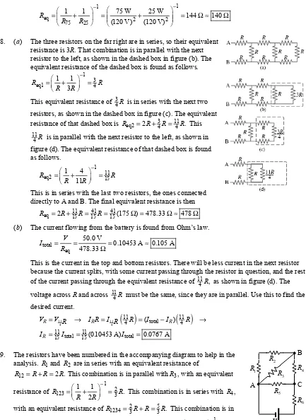
18. (a) The three resistors on the far right are in series, so their equivalent resistance is 3R. That combination is in parallel with the next resistor to the left, as shown in the dashed box in figure (b). The equivalent resistance of the dashed box is found as follows.
1 3
eq1 4
1 1 3
R R
R R
−
⎛ ⎞
=⎜⎝ + ⎟⎠ =
This equivalent resistance of 3
4R is in series with the next two resistors, as shown in the dashed box in figure (c). The equivalent resistance of that dashed box is 3 11
eq2 2 4 4 .
R = R+ R= R This 11
4R is in parallel with the next resistor to the left, as shown in figure (d). The equivalent resistance of that dashed box is found as follows.
1 11
eq2 1 4 15
11
R R
R R
−
⎛ ⎞
=⎜ + ⎟ =
⎝ ⎠
This is in series with the last two resistors, the ones connected directly to A and B. The final equivalent resistance is then
11 41 41
eq 2 15 15 15(175 ) 478 33 478 R = R+ R= R= Ω = . Ω ≈ Ω (b) The current flowing from the battery is found from Ohm’s law.
total eq
50 0 V
0 10453 A 0 105 A 478 33
V I
R
.
= = = . ≈ .
. Ω
This is the current in the top and bottom resistors. There will be less current in the next resistor because the current splits, with some current passing through the resistor in question, and the rest of the current passing through the equivalent resistance of 11
4R, as shown in figure (d). The voltage across R and across 11
4R must be the same, since they are in parallel. Use this to find the desired current.
( )
( )
11 11
4 4
11 11
total
4 4
11 11
total total
15 15
( )
(0.10453 A) 0.0767 A
R R R
R
V V R I R I R R I I R
I I I
= → = = − →
= = =
19. The resistors have been numbered in the accompanying diagram to help in the analysis. R1 and R2 are in series with an equivalent resistance of
12 2 .
R = + =R R R This combination is in parallel withR3, with an equivalent resistance of
1 2
123 1 1 3 .
2
R R
R R
−
⎛ ⎞
=⎜ + ⎟ =
⎝ ⎠ This combination is in series with R4,
with an equivalent resistance of 2 5
1234 3 3 .
R = R R+ = R This combination is in parallel with R5, with an equivalent resistance of
1 5
12345 8
1 3 .
5
R R
R R
−
⎛ ⎞
=⎜⎝ + ⎟⎠ =
6
R
1
R 2
R
3
R
5
R
4
R
V A
B
Finally, this combination is in series with R6, and we calculate the final equivalent resistance.
5 13
eq 8 8
R = R R+ = R
A more detailed solution with more circuit diagrams is given in Problem 20.
20. We reduce the circuit to a single loop by combining series and parallel combinations. We label a combined resistance with the subscripts of the resistors used in the combination. See the successive diagrams. The initial diagram has been rotated by 90 degrees.
1
R and R2 are in series.
12 1 2 2
R =R +R = + =R R R
12
R and R3 are in parallel.
1 1
2
123 3
12 3
1 1 1 1
2
R R
R R R R
− −
⎛ ⎞ ⎛ ⎞
=⎜ + ⎟ =⎜⎝ + ⎟⎠ =
⎝ ⎠
123
R and R4 are in series.
5 2
1234 123 4 3 3
R =R +R = R R+ = R
1234
R and R5 are in parallel.
1 1
5
12345 5 8
1234 5 3
1 1 1 1
R R
R R R R
− − ⎛ ⎞ ⎛ ⎞ ⎜ ⎟ =⎜ + ⎟ =⎜ + ⎟ = ⎝ ⎠ ⎝ ⎠ 12345
R and R6 are in series, producing the equivalent resistance.
5 13
eq 12345 6 8 8
R =R +R = R R+ = R
Now work “backward” from the simplified circuit. Resistors in series have the same current as their equivalent resistance, and resistors in parallel have the same voltage as their equivalent resistance. To avoid rounding errors, we do not use numeric values until the end of the problem.
eq 13 6 12345
eq 8 8 13
I I I
R R R
= Ᏹ = Ᏹ = Ᏹ = =
5 5 13
5 5
5 1234 12345 12345 12345 8 13 5 5
5
8 5
( ) ;
13 13
V
V V V I R R I I
R R R R
⎛ ⎞
= = = =⎝⎜ Ᏹ ⎟⎠ = Ᏹ = = Ᏹ= Ᏹ =
5
1234 13 2 2
1234 5 4 123 123 123 123 3 13 12 3
1234 3
3 3
; ( )
13 13
V
I I I V I R R V V
R R R R
⎛ ⎞
= = Ᏹ= Ᏹ = = = =⎜⎝ Ᏹ⎟⎠ = Ᏹ= =
2
3 12 13
3 3 12 1 2
3 12
2 ;
13 2 13
V V
I I I I I
R R R R R
= = Ᏹ = = = Ᏹ= Ᏹ = =
Now substitute in numerical values.
1 2 3 4
2
5 6 AB 3 13
12 0 V 0 284 mA ; 2 0 568 mA ; 3 0 852 mA ;
13 13(3250 ) 13 13
5 1 42 mA ; 8 2 27 mA ; 1 85 V
13 13
I I I I
R R R
I I V V
R R
.
= = = = . = = . = = .
Ω
= = . = = . = = = .
Ᏹ Ᏹ Ᏹ
Ᏹ Ᏹ Ᏹ
21. It is given that the power used when the resistors are in series is one-fourth the power used when the resistors are in parallel. The voltage is the same in both cases. Use Eq. 18–6b, along with the definitions of series and parallel equivalent resistance.
2 2
1 2
1 1
series 4 parallel 4 series parallel 1 2
series parallel 1 2
4 ( ) 4
( )
R R
V V
P P R R R R
R R R R
= → = → = → + = →
+
2 2 2 2
1 2 1 2 1 1 2 2 1 2 1 2 1 2
(R +R ) =4R R → R +2R R +R −4R R = =0 (R −R ) → R =R Thus the two resistors must be the same, so the “other” resistor is 4 8 k .. Ω
22. We label identical resistors from left to right as Rleft,Rmiddle, and Rright. When the switch is opened, the equivalent resistance of the circuit increases from 32R r+ to 2R r+ . Thus the current delivered by the battery decreases, from 3
2R r+
Ᏹ to . 2R r+
Ᏹ Note that this is LESS than a 50% decrease.
(a) Because the current from the battery has decreased, the voltage drop across Rleft will decrease, since it will have less current than before. The voltage drop across Rright decreases to 0, since no current is flowing in it. The voltage drop across Rmiddle will increase, because even though the total current has decreased, the current flowing through Rmiddle has increased since before the switch was opened, only half the total current was flowing through Rmiddle.
leftdecreases; middleincreases; right goes to 0
V V V
(b) By Ohm’s law, the current is proportional to the voltage for a fixed resistance. leftdecreases; middleincreases; right goes to 0
I I I
(c) Since the current from the battery has decreased, the voltage drop across r will decrease, and thus the terminal voltage increases.
(d) With the switch closed, the equivalent resistance is 3
2R r+ . Thus the current in the circuit is closed 3
2 , I
R r =
+
Ᏹ and the terminal voltage is given by Eq. 19–1.
terminal closed 3 3 3
closed 2 2 2
0 50 1 (9 0 V) 1
(5.50 ) 0.50 8.486 V 8.5 V
r
V I r r
R r R r
⎛ ⎞ ⎛ . Ω ⎞
= − = − = ⎜⎜ − ⎟⎟= . ⎜⎜ − ⎟⎟
+ ⎝ + ⎠ ⎝ Ω + Ω⎠
= ≈
Ᏹ
(e) With the switch open, the equivalent resistance is 2R r+ . Thus the current in the circuit is
closed ,
2 I
R r =
+
Ᏹ and again the terminal voltage is given by Eq. 19–1.
terminal closed closed
0 50
1 (9 0 V) 1
2 2 2(5 50 ) 0 50
8.609 V 8 6 V
r
V I r r
R r R r
⎛ . Ω ⎞
⎛ ⎞
= − = − + = ⎜⎝ − + ⎟⎠= . ⎜ − . Ω + . Ω⎟
⎝ ⎠
= ≈ .
Ᏹ
Ᏹ Ᏹ Ᏹ
23. Find the maximum current and resulting voltage for each resistor under the power restriction. 2
2
3
1400 3 1800
, 0 5 W
0 0189 A (0 5 W)(1 4 10 ) 26 5 V 1 4 10
V P
P I R I V RP
R R
I V
= = → = =
.
= = . = . . × Ω = .
. × Ω
3
2500 0 5 W3 0 0141 A 2500 (0 5 W)(2 8 10 ) 35 4 V 2 5 10
I = . = . V = . . × Ω = .
. × Ω
3
3700 0 5 W3 0 0116 A 3700 (0 5 W)(3 7 10 ) 43 0 V 3 7 10
I = . = . V = . . × Ω = .
. × Ω
The parallel resistors have to have the same voltage, so the voltage across that combination is limited to 35.4 V. That would require a current given by Ohm’s law and the parallel combination of the two resistors.
parallel
parallel parallel
parallel 2500 3700
1 1 1 1
(35 4 V) 0 0237 A
2500 3700 V
I V
R R R
⎛ ⎞ ⎛ ⎞
= = ⎜ + ⎟= . ⎜ + ⎟= .
Ω Ω
⎝ ⎠
⎝ ⎠
This is more than the maximum current that can be in R1400. Thus the maximum current that R1400 can carry, 0.0189 A, is the maximum current for the circuit. The maximum voltage that can be applied across the combination is the maximum current times the equivalent resistance. The equivalent
resistance is the parallel combination of R2500 and R3700 added to R1400.
1 1
max max eq max 1800
2800 3700
1 1 1 1
(0 0189 A) 1400
2500 3700 54.66 V 55 V
V I R I R
R R
− −
⎡ ⎛ ⎞ ⎤ ⎡ ⎛ ⎞ ⎤
⎢ ⎥ ⎢ ⎥
= = ⎜ + ⎟ = . Ω⎜ + ⎟
Ω Ω
⎢ ⎝ ⎠ ⎥ ⎢⎣ ⎝ ⎠ ⎥⎦
⎣ ⎦
= ≈
24. (a) Note that adding resistors in series always results in a larger resistance, and adding resistors in parallel always results in a smaller resistance. Closing the switch adds another resistor in parallel with R3 and R4, which lowers the net resistance of the parallel portion of the circuit and thus lowers the equivalent resistance of the circuit. That means that more current will be delivered by the battery. Since R1 is in series with the battery, its voltage will increase. Because of that increase, the voltage across R3 and R4 must decrease so that the total voltage drops around the loop are equal to the battery voltage. Since there was no voltage acrossR2 until the switch was closed, its voltage will increase. To summarize:
1and 2increase; 3and 4decrease
(b) By Ohm’s law, the current is proportional to the voltage for a fixed resistance. Thus 1and 2increase; 3and 4decrease
I I I I
(c) Since the battery voltage does not change and the current delivered by the battery increases, the power delivered by the battery, found by multiplying the voltage of the battery by the current delivered, increases .
(d) Before the switch is closed, the equivalent resistance is R3 and R4 in parallel, combined with 1
R in series.
1 1
eq 1
3 4
1 1 2
155 232 5
155
R R
R R
− −
⎛ ⎞ ⎛ ⎞
= +⎜ + ⎟ = Ω +⎜ ⎟ = . Ω Ω
⎝ ⎠
⎝ ⎠
The current delivered by the battery is the same as the current through R1. battery
total 1
eq
22 0 V 0 09462 A 232 5
V
I I
R
.
= = = . =
. Ω
The voltage across R1 is found by Ohm’s law. 1 1 (0 09462 A)(155 ) 14 666 V
V =IR = . Ω = .
The voltage across the parallel resistors is the battery voltage less the voltage across R1. p battery 1 22 0 V 14 666 V 7 334 V
V =V − = .V − . = .
The current through each of the parallel resistors is found from Ohm’s law. p
3 4
2
7 334 V
0 04732 A 155
V
I I
R .
= = = . =
Ω
Notice that the current through each of the parallel resistors is half of the total current, within the limits of significant figures. The currents before closing the switch are as follows.
1 0 0946 A 3 4 0 0473 A I = . I =I = .
After the switch is closed, the equivalent resistance isR R2, 3, and R4 in parallel, combined with 1
R in series. Do a similar analysis.
1 1
eq 1
2 3 4
1 1 1 3
155 206.7
155
R R
R R R
− −
⎛ ⎞ ⎛ ⎞
= +⎜ + + ⎟ = Ω +⎜ ⎟ = Ω
Ω
⎝ ⎠
⎝ ⎠
battery
total 1 1 1
eq
22.0 V
0.1064 A (0.1064 A)(155 ) 16.49 V 206.7
V
I I V IR
R
= = = = = = Ω =
Ω
p
p battery 1 2 3 4
2
5.51 V
22.0 V 16.49 V 5.51 V 0.0355 A 155
V
V V V I I I
R
= − = − = = = = = =
Ω
Notice that the current through each of the parallel resistors is one-third of the total current, within the limits of significant figures. The currents after closing the switch are as follows.
1 0 106 A 2 3 4 0 0355 A I = . I =I =I = .
25. All of the resistors are in series, so the equivalent resistance is just the sum of the resistors. Use Ohm’s law to find the current, and show all voltage changes starting at the negative pole of the battery and going counterclockwise.
eq
9 0 V 0 3529 A 0 35 A (9 5 14 0 2 0)
voltages 9 0 V (9 5 )(0 3529 A) (14 0 )(0 3529 A) (2 0 )(0 3529 A) 9 0 V 3 35 V 4 94 V 0 71 V 0
I R
.
= = = . ≈ .
. + . + . Ω
= . − . Ω . − . Ω . − . Ω .
= . − . − . − . =
∑
Ᏹ
26. Apply Kirchhoff’s loop rule to the circuit, starting at the upper left corner of the circuit diagram, in order to calculate the current. Assume that the current is flowing clockwise.
6 V
(2 0 ) 18 V (4 8 ) 12 V (1 0 ) 0 0 769 A 7 8
I I I I
− . Ω + − . Ω − − . Ω = → = = .
. Ω
The terminal voltage for each battery is found by summing the potential differences across the internal resistance and emf from left to right. Note that for the 12-V battery, there is a voltage gain going across the internal resistance from left to right.
terminal terminal
18-V battery: (2 0 ) 18 V (0 769 A)(2 0 ) 18 V 16 46 V 16 V 12-V battery: (1 0 ) 12 V (0 769 A)(1 0 ) 12 V 12 769 V 13 V
V I
V I
= − . Ω + = − . . Ω + = . ≈
= . Ω + = . . Ω + = . ≈
27. To find the potential difference between points a and b, the current must be found from Kirchhoff’s loop law. Start at point a and go counterclockwise around the entire circuit, taking the current to be counterclockwise.
ab a b
0
2
2 2 0
2
IR IR IR IR I
R
V V V IR IR IR R
R
− + − − + − = → =
= − = − + − = − = − =
Ᏹ
Ᏹ Ᏹ
Ᏹ
Ᏹ Ᏹ Ᏹ
Notice that the actual values for the battery voltages and the resistances were not used. 28. (a) There are three currents involved, so there must be three independent
equations to determine those three currents. One comes from
Kirchhoff’s junction rule applied to the junction of the three branches on the right of the circuit.
2 1 3 1 2 3
I = +I I → I =I −I
Another equation comes from Kirchhoff’s loop rule applied to the top loop, starting at the negative terminal of the battery and progressing clockwise.
1−I R1 1−I R2 2 =0 → 9 25= I1+68I2 Ᏹ
The final equation comes from Kirchhoff’s loop rule applied to the bottom loop, starting at the negative terminal of the battery and progressing counterclockwise.
2−I R3 3−I R2 2 =0 → 12 35= I3+68I2 Ᏹ
Substitute I1=I2−I3 into the top loop equation, so that there are two equations with two unknowns.
1 2 2 3 2 2 3 3 2
9 25= I +68I =25(I −I ) 68+ I =93I −25 ; 12 35I = I +68I
1
Ᏹ
2
Ᏹ
2
R
3
R
2
I
3
I
1
R
1
Solve the bottom loop equation for I2 and substitute into the top loop equation, resulting in an equation with only one unknown, which can be solved.
3
3 2 2 12 35
12 35 68
68 I
I I I −
= + → =
3
2 3 12 35 3 3 3
9 93 25 93 25 612 1116 3255 1700 68
I
I I ⎛ − ⎞ I I I
= − = ⎜ ⎟− → = − − →
⎝ ⎠
3
3 2
12 35
504 0.1017 A 0.10 A, up ; 0.1241 A 0.12 A, left
4955 68
I
I = = ≈ I = − = ≈
1 2 3 0.0224 A 0.02 A, right I =I − =I ≈
(b) We can include the internal resistances simply by adding 1 0. Ω to R1 and R3. So let R1=26Ω and let R3=36Ω. Now re-work the problem exactly as in part (a).
2 1 3 1 2 3
I = +I I → I =I −I
1−I R1 1−I R2 2 =0 → 9 26= I1+68I2 Ᏹ
2−I R3 3−I R2 2 =0 → 12 36= I3+68I2 Ᏹ
1 2 2 3 2 2 3 3 2
9 26= I +68I =26(I −I ) 68+ I =94I −26 ; 12 36I = I +68I
3 3
3 2 2 12 36 3 9
12 36 68
68 17
I I
I I I − −
= + → = =
3
2 3 3 3 3
3
3 2
1 2 3
3 9
9 94 26 94 26 153 282 846 442
17
3 12
129 0 1002 A 0 10 A, up ; 0 1234 A 0 12 A, left
1288 17
0 0232 A 0 02 A, right I
I I I I I
I
I I
I I I
−
⎛ ⎞
= − = ⎜ ⎟− → = − − →
⎝ ⎠
−
= = . ≈ . = = . ≈ .
= − = . ≈ .
The currents are unchanged to the nearest 0.01 A by the inclusion of the internal resistances. 29. This circuit is identical to Example 19–8 and Fig. 19–13 except for the numeric values. So we may
copy the equations developed in that Example but use the current values. Eq. (i): I3= +I1 I2 Eq. (ii): −34I1+45 48− I3=0
Eq. (iii): −34I1+19I2−85 0= Eq. (iv): I2=85 34+19 I1= .4 474 1 789+ . I1
Eq. (v): 3 45 341 0 938 0 7081 48
−
= I = . − .
I I
3 1 2 1 1 1 1
2 1 3 1
0.938 0.708 4.474 1.789 1.011 A 4 474 1 789 2 665 A; 0 938 0 708 1 654 A
I I I I I I I
I I I I
= + → − = + + → = −
= . + . = . = . − . = .
(a) To find the potential difference between points a and d, start at point a and add each individual potential difference until reaching point d. The simplest way to do this is along the top branch. Vad =Vd−Va = −I1(34 )Ω = − − .( 1 011 A)(34 ) 34 37 VΩ = . ≈ 34 V
Slight differences might be obtained in the final answer depending on the branch used, due to rounding. For example, using the bottom branch, we get the following.
ad = d− a = 1− 2(19 ) 85 V (2 665 A)(19 ) 34 365 V 34 VΩ = − . Ω = . ≈
(b) For the 85-V battery, the terminal voltage is the potential difference from point g to point e. For the 45-V battery, the terminal voltage is the potential difference from point d to point b.
terminal 1 2
terminal 2 3
85 V battery: 85 V (2 665 A)(1 0 ) 82 V 45 V battery: 45 V (1 654 A)(1 0 ) 43 V
V I r
V I r
= = − = − . . Ω =
= = − = − . . Ω =
Ᏹ Ᏹ
30. There are three currents involved, so there must be three independent equations to determine those three currents. One comes from Kirchhoff’s junction rule applied to the junction of the three branches at the top center of the circuit.
I1=I2+I3
Another equation comes from Kirchhoff’s loop rule applied to
the left loop, starting at the negative terminal of the battery and progressing counterclockwise. 58 V−I1(120 )Ω −I1(74 )Ω −I2(56 ) 0Ω = → 58 194= I1+56I2
The final equation comes from Kirchhoff’s loop rule applied to the right loop, starting at the negative terminal of the battery and progressing counterclockwise.
3 0 V. −I3(25 )Ω +I2(56 )Ω −I3(110 ) 0Ω = → 3= −56I2+135I3
Substitute I1=I2+I3 into the left loop equation, so that there are two equations with two unknowns. 58 194(= I2+I3) 56+ I2=250I2+194I3
Solve the right loop equation for I2 and substitute into the left loop equation, resulting in an equation with only one unknown, which can be solved.
3 3
2 3 2 2 3 3
3
3
3 2 1 2 3
135 3 135 3
3 56 135 ; 58 250 194 250 194
56 56
3998 44614
135 3
0 08961 A; 0 1625 A; 0 2521 A 56
I I
I I I I I I
I
I
I I I I I
− ⎛ − ⎞
= − + → = = + = ⎜ ⎟+ →
⎝ ⎠
=
−
= . = = . = + = .
The current in each resistor is as follows:
120 : 0 25 A 74 : 0 25 A 56 : 0 16 A 25 : 0 090 A 110 : 0 090 AΩ . Ω . Ω . Ω . Ω .
31. Because there are no resistors in the bottom branch, it is possible to write Kirchhoff loop equations that only have one current term, making them easier to solve. To find the current through R1, go around the outer loop counterclockwise, starting at the lower left corner.
3 1 1 1 1 3 1
1
6 0 V 9 0 V
0 0 68 A, left
22 V V
V I R V I
R
+ . + .
− + = → = = = .
Ω
1
I I3
2
I 3.0V
58V
120Ω
1.4Ω 1.4Ω
18Ω
22Ω 1
I
2
I
3
I
6.0V 9.0V
To find the current through R2, go around the lower loop counterclockwise, starting at the lower left corner.
3
3 2 2 2
2
6 0 V
0 0 33 A, left
18 V
V I R I
R .
− = → = = = .
Ω
32. There are three currents involved, so there must be three independent equations to determine those three currents. One comes from Kirchhoff’s junction rule applied to the junction of the three branches on the left of the circuit.
1 2 3
I =I +I
Another equation comes from Kirchhoff’s loop rule applied to the outer loop, starting at the lower left corner and progressing counterclockwise.
3 1 1
1 3
(1 4 ) 6 0 V (22 ) (1 4 ) 9 0 V 0 15 23 4 1 4
I I I
I I
− . Ω + . − Ω − . Ω + . = → = . + .
The final equation comes from Kirchhoff’s loop rule applied to the bottom loop, starting at the lower left corner and progressing counterclockwise.
3(1 4 ) 6 0 V 2(18 ) 0 6 18 2 1.4 3
I I I I
− . Ω + . + Ω = → = − +
Substitute I1=I2+I3 into the top loop equation, so that there are two equations with two unknowns.
1 3 2 3 3 2 3 2 3
15 23 4= . I + .1 4I = .23 4(I +I ) 1 4+ . I = .23 4I + .24 8 ; 6I = −18I + .1 4I
Solve the bottom loop equation for I2 and substitute into the top loop equation, resulting in an equation with only one unknown, which can be solved.
3
2 3 2
3
2 3 3 3 3
6 1 4 6 18 1 4
18 6 1 4
15 23 4 24 8 23 4 24 8 270 140 4 32 76 446 4 18
− + .
= − + . → =
− + .
⎛ ⎞
= . + . = . ⎜ ⎟+ . → = − . + . + . →
⎝ ⎠
I
I I I
I
I I I I I
3
3 2
1 2 3
6 1 4
410 4 0 8565 A ; 6 1 4(0 8565) 0 2667 A 0 27 A, left
479 16 18 18
0 5898 A 0 59 A, left I
I I
I I I
− + .
. − + . .
= = . = = = − . ≈ .
.
= + = . ≈ .
33. (a) We label each of the currents as shown in the
accompanying figure. Using Kirchhoff’s junction rule and the first three junctions (a–c), we write equations relating the entering and exiting currents.
1 2
2 3 4
1 4 5
[1] [2] [3] I I I
I I I I I I
We use Kirchhoff’s loop rule to write equations for loops abca, abcda, and bdcb.
2 4 1
2 3
3 5 4
0 [4] 0 [5] 0 [6]
I R I R I R I R I R I R I R I R = − − + = − − + = − + +
Ᏹ
We have six unknown currents and six equations. We solve these equations by substitution. First, insert Eq. [3] into [6] to eliminate current I5. Next insert Eq. [2] into Eqs. [1], [4], and [5] to eliminate I2.
3 1 4 4 3 1 4
1 3 4
3 4 4 1 3 4 1
3 4 3 4 3
0 ( ) 0 2 R [6 ]
[1 ]
0 ( ) 0 2 R [4 ]
0 ( ) 0 2 [5 ]
I R I I R I R I R I R I
I I I I
I I R I R I R I R I I R
I I R I R I R I R
= − + + + → = − + + ′
= + + ′
= − + − + → = − − + ′
= − + − +Ᏹ → = − − +Ᏹ ′
Next we solve Eq. [4′] for I4 and insert the result into Eqs. [1′], [5′], and [6′].
1 1
3 4 1 4 2 1 2 3
3
1 1 1
1 3 2 1 2 3 2 1 2 3
1 1
3 1 2 1 2 3 3 1 1 3
3
1 1 1
1 3 3 1 3
2 2 2 2
0 2
[1 ]
0 2( ) 2 2 R [6 ]
0 ( ) 2 0 R [5 ]
I R I R I R I I I
I I I I I I I I
I R I R I I R I R I I I
I I R I R I R I
= − − + → = −
= + + − → = + ″
= − + + − = − + → − ″
= − − − +Ᏹ → = − − +Ᏹ ″
Finally we substitute Eq. [6″] into Eq. [5″] and solve for I1. We insert this result into Eq. [1″] to write an equation for the current through the battery in terms of the battery emf and resistance.
3 3
1 1
1 1 1 1 1 1
2 2 2 2
0 ; 2
2
I R I R I I I I I I
R R
= − − +Ᏹ → = Ᏹ = + = → = Ᏹ
(b) We divide the battery emf by the current to determine the effective resistance.
eq
/
R R
I R
= =Ᏹ Ᏹ =
Ᏹ
34. (a) Since there are three currents to determine, there must be three independent equations to determine those three currents. One comes from Kirchhoff’s junction rule applied to the junction near the negative terminal of the middle battery.
1 2 3
I =I +I
Another equation comes from Kirchhoff’s loop rule applied to the top loop, starting at the negative terminal of the middle battery and progressing counterclockwise. We add series resistances.
2 1 1 2
12 0 V. −I (12 ) 12 0 VΩ + . −I (35 ) 0Ω = → 24 35= I +12I
The final equation comes from Kirchhoff’s loop rule applied to the bottom loop, starting at the negative terminal of the middle battery and progressing clockwise.
2 3 2 3
Substitute I1=I2+I3 into the top loop equation, so that there are two equations with two unknowns.
1 2 2 3 2 2 3
24 35= I +12I =35(I +I ) 12+ I =47I +35I
Solve the bottom loop equation for I2 and substitute into the top loop equation, resulting in an equation with only one unknown, which can be solved for I3.
3 3 3
2 3 2 2 3 3
3
3 2 1 2 3
6 28 3 14 3 14
6 12 28 ; 24 47 35 47 35
12 6 6
6 28
3 46 mA ; 0 508 A ; 0 511 A
12
I I I
I I I I I I
I
I I I I I
+ + ⎛ + ⎞
= − → = = = + = ⎜ ⎟+ →
⎝ ⎠
+
= . = = . = + = .
(b) The terminal voltage of the 6.0-V battery is 6 0 V. −I r3 = .6 0 V (3 46 10− . × −3A)(1 0 ). Ω 5 997 V 6 0 V
= . ≈ . .
35. This problem is the same as Problem 34, except the total resistance in the top branch is now 23Ω
instead of 35Ω. We simply reproduce the adjusted equations here without the prose.
1 2 3
2 1 1 2
2 3 2 3
1 2 2 3 2 2 3
12 0 V (12 ) 12 0 V (23 ) 0 24 23 12 12 0 V (12 ) 6 0 V (28 ) 0 6 12 28
24 23 12 23( ) 12 35 23
I I I
I I I I
I I I I
I I I I I I I
= +
. − Ω + . − Ω = → = +
. − Ω − . + Ω = → = −
= + = + + = +
3 3 3
2 3 2 2 3 3
3
3
3 2 1 2 3
6 28 3 14 3 14
6 12 28 ; 24 35 23 35 23
12 6 6
39 628
6 28
0 0621 A; 0 6449 A; 0 707 A 0 71 A
12
I I I
I I I I I I
I
I
I I I I I
+ + ⎛ + ⎞
= − → = = = + = ⎜ ⎟+ →
⎝ ⎠
=
+
= . = = . = + = . ≈ .
36. Define I1 to be the current to the right through the 2.00-V battery (Ᏹ1), andI2 to be the current to the right through the 3.00 V battery (Ᏹ2). At the junction, they combine to give current I I= +1 I2 to the left through the top branch. Apply Kirchhoff’s loop rule, first to the upper loop and then to the outer loop, and solve for the currents.
1 1 1 2 1 1 2
2 2 1 2 2 1 2
( ) 0 ( ) 0
( ) 0 ( ) 0
I r I I R R r I RI
I r I I R RI R r I
− − + = → − + − =
− − + = → − − + =
Ᏹ Ᏹ
Ᏹ Ᏹ
Solve the first equation for I2 and substitute into the second equation to solve forI1.
1 1 1
1 1 2 2 1
2 1 2 1 1
1
1 2 1
( ) 2 00 4 350
( ) 0 0 500 1 0875
4 00 ( ) 3 00 4 00 (4 35)(0 500 1 0875 ) 0 0 825 0 7306
1 129 A; 0 500 1 0875 1 728 A
R r I I
R r I RI I I
R
RI R r I I I
I
I I I
− + . − .
− + − = → = = = . − .
.
− − + = . − . − . . − . = →
. = − .
= − . = . − . = .
Ᏹ Ᏹ
Ᏹ
R
r
1
I
2
I
1 2
I +I Ᏹ
2 Ᏹ
The voltage across R is its resistance times I= +I1 I2.
1 2
( ) (4 00 )( 1 129 A 1 728 A) 2 396 V 2 40 V
= + = . Ω − . + . = . ≈ .
R
V R I I
Note that the top battery is being charged—the current is flowing through it from positive to negative. 37. Take 100 of the batteries and connect them in series, which would give a total voltage of 300 volts. Do
that again with the next 100 batteries, and again with the last 100 batteries. That gives three sets, each with a total voltage of 300 volts. Then those three sets can be connected in parallel with each other. The total combination of batteries would have a potential difference of 300 volts.
Another possibility is to connect three batteries in parallel, which would provide a potential difference of 3 volts. Make 100 sets of those three-battery combinations and connect those 100 sets in series. That total combination would also have a potential difference of 300 volts.
38. (a) Capacitors in parallel add according to Eq. 19–5.
Ceq=C1+C2+C3+C4+C5+C6=6(4.8 10× −6F)= 2.88 10× −5F =28.8 Fμ (b) Capacitors in series add according to Eq. 19–6.
1
1 6
7
eq 6
1 2 3 4 5 6
1 1 1 1 1 1 6 4.8 10 F 8.0 10 F
6 4.8 10 F
C
C C C C C C
−
− −
− −
⎛ ⎞
⎛ ⎞ ×
=⎜ + + + + + ⎟ =⎜⎜ ⎟⎟ = = ×
×
⎝ ⎠ ⎝ ⎠
39. The series capacitors add reciprocally, and then the parallel combination is found by adding linearly. 1
1
6 6
eq 3 6 6
1 2
1 1 1 1 2.00 10 F 3.71 10 F 3.71 F
3.00 10 F 4.00 10 F
C C
C C μ
− −
− −
− −
⎛ ⎞
⎛ ⎞
=⎜ + ⎟ + =⎜⎜ + ⎟⎟ + × = × =
× ×
⎝ ⎠ ⎝ ⎠
40. (a) The full voltage is across the 2.00- Fμ capacitor, so V3=21.0 V . To find the voltage cross the two capacitors in series, find their equivalent capacitance and the charge stored. That charge will be the same for both of the series capacitors. Finally, use that charge to determine the voltage on each capacitor. The sum of the voltages across the series capacitors is 26.0 V.
1 1
6
eq 6 6
1 2
6 5
eq eq
5 5
eq eq
1 6 2 6
1 1 1 1
1.714 10 F 3.00 10 F 4.00 10 F
(1.714 10 F)(21.0 V) 3.599 10 C
3.599 10 C 3.599 10 C
12.0 V 9.0 V
3.00 10 F 4.00 10 F
C
C C Q C V
Q Q
V V
C C
− −
−
− −
− −
− −
− −
⎛ ⎞
⎛ ⎞
=⎜ + ⎟ =⎜⎜ + ⎟⎟ = ×
× ×
⎝ ⎠ ⎝ ⎠
= = × = ×
× ×
= = = = = =
× ×
(b) We have found two of the three charges already. The charge Qeq =3.599 10× −5C is the charge on the two capacitors in series. The other charge is found by using the full voltage.
6 5
3 3
5 5
1 2 3
(2.00 10 F)(21.0 V) 4.20 10 C 3.60 10 C; 4.20 10 C Q C V
Q Q Q
− −
− −
= = × = ×
41. To reduce the net capacitance, another capacitor must be added in series.
1 eq
eq 1 2 2 eq 1 1 eq
1 1 1 1 1 1 C C
C C C C C C C C
−
= + → = − = →
9 9
1 eq 9
2 9 9
1 eq
(2.9 10 F)(1.2 10 F)
2.047 10 F 2.0 nF (2.9 10 F) (1.2 10 F)
C C C
C C
− −
−
− −
× ×
= = = × ≈
− × − ×
Yes, an existing connection needs to be broken in the process. One of the connections of the original capacitor to the circuit must be disconnected in order to connect the additional capacitor in series. 42. Capacitors in parallel add linearly, so adding a capacitor in parallel will increase the net capacitance
without removing the 5.0- Fμ capacitor.
7.0 Fμ + =C 16 Fμ → C= 9 F connected in parallelμ
43. The maximum capacitance is found by connecting the capacitors in parallel.
Cmax =C1+C2+C3=3.2 10× −9F 5.8 10+ × −9F 1.00 10+ × −8F= 1.90 10× −8F in parallel The minimum capacitance is found by connecting the capacitors in series.
1 1
9
min 9 9 8
1 2 3
1 1 1 1 1 1 1.7 10 F in series
3.2 10 F 5.8 10 F 1.00 10 F C
C C C
− −
−
− − −
⎛ ⎞
⎛ ⎞
=⎜ + + ⎟ =⎜⎜ + + ⎟⎟ = ×
× × ×
⎝ ⎠ ⎝ ⎠
44. From the diagram, we see that C1and C2 are in parallel and 3
C and C4 are in parallel. Those two combinations are then in series with each other. Use those combinations to find the equivalent capacitance. We use subscripts to indicate which capacitors have been combined.
C12 =C1+C C2; 34=C3+C4;
1234 12 34 1 2 3 4
1 1 1 1 1
C =C +C =C +C +C +C →
1 2 3 4
1234
1 2 3 4
( )( )
( )
C C C C
C
C C C C
+ +
=
+ + +
45. The voltage across C1 is the full 10 V from the battery. Since the other two capacitors are identical, they will each have 5 V across them so that the total voltage across the two of them is 10 V. Thus
1/ 2 10 V/5 V 2/1.
V V = =
46. When the capacitors are connected in series, they each have the same charge as the net capacitance.
(a)
1 1
1 2 eq eq 6 6
1 2
1 1 1 1
(9.0 V) 0.50 10 F 1.40 10 F
Q Q Q C V V
C C
− −
− −
⎛ ⎞
⎛ ⎞
= = = =⎜ + ⎟ =⎜⎜ + ⎟⎟
× ×
⎝ ⎠ ⎝ ⎠
6
6
1 2
1 6 2 6
1 2
3.316 10 C
3.316 10 C 3.316 10 C
6.632 V 6.6 V 2.369 V 2.4 V
0.50 10 F 1.4 10 F
Q Q
V V
C C
−
−6 −
− −
= ×
× ×
= = = ≈ = = = ≈