www.geosci-instrum-method-data-syst.net/5/65/2016/ doi:10.5194/gi-5-65-2016
© Author(s) 2016. CC Attribution 3.0 License.
A new high-precision and low-power GNSS receiver for long-term
installations in remote areas
David H. Jones, Carl Robinson, and G. Hilmar Gudmundsson British Antarctic Survey, High Cross, Madingley Road, Cambridge, UK Correspondence to: G. Hilmar Gudmundsson ([email protected])
Received: 22 June 2015 – Published in Geosci. Instrum. Method. Data Syst. Discuss.: 17 August 2015 Revised: 17 March 2016 – Accepted: 17 March 2016 – Published: 24 March 2016
Abstract. We have developed a new high-precision GNSS receiver specifically designed for long-term unattended de-ployments in remote areas. The receiver reports its status, and can be reprogrammed remotely, through an integrated satel-lite data link. It uses less power than commercially available alternatives while being equally, if not more, accurate. Data are saved locally on dual SD card slots for increased relia-bility. Deployments of a number of those receivers in sev-eral different locations on the Antarctic ice sheet have shown them to be robust and able to operate flawlessly at low tem-peratures down to−40◦C.
1 Introduction
Long-term monitoring using permanently installed GNSS re-ceivers is a powerful tool for geophysics research, and this technique is now commonly used in various different set-tings. Applications are too numerous to list but include mea-surements of glacier flow, tectonic movements, ground subsi-dence and isostatic uplift, to name a few. In such applications the reliability of the system is of utmost concern as the GNSS units are often left unattended for prolonged periods of times. Here we discuss the development and testing of a new simple-to-use, reliable, low-power and low-cost GNSS re-ceiver unit, for use in remote areas. We describe the design and performance of a new GNSS unit that fits all those cri-teria. Although we believe our new GNSS receiver to be of general use for the wider geophysical sciences community, we will specifically focus on its application to remote polar areas. This is because our own primary application of GNSS receivers is to monitor the temporal variation in glacier flow in Antarctica.
Here we use the word “receiver” to include the signal tracking and control circuits, internal power supplies, com-munications and logging hardware. We do not include the antenna or field installation hardware.
1.1 The need for a new GNSS receiver
Field installations of GNSS receivers in remote areas require a reliable and sustainable power source. A common solution is the use of batteries with supplementary solar panels. In po-lar areas, where there is insufficient sunlight for much of the winter, wind turbines are also often employed, together with large battery packs to ensure continuous power over periods of low winds (Rose et al., 2009; Bauguitte et al., 2011). Fig-ures 1 and 2 show a typical polar GNSS installation used by the British Antarctic Survey for over-winter deployment of GNSS units. As the figure shows the power system is fairly large and the weight of these batteries, wind turbines, so-lar panels and their necessary scaffolding is not insignificant, and often determines the upper limit of the scope of any po-lar installation. The power consumption of a GNSS receiver therefore puts significant constraints on their applicability in remote areas.
Figure 1. GNSS station installed on the Institute Ice Stream show-ing the two wind turbines and solar panels required to power the GNSS receiver.
Figure 2. six 100 Ah batteries in three battery enclosures, for the field installation of Fig. 1. In total, the batteries and enclosures weighed 300 kg, nearly half of the aircraft payload available for the site installation.
static deployments, actually make such units less reliable and complicate their use.
Based on our experience in the use of commercial GNSS monitoring systems in polar areas acquired over more than a decade, common sources of failure in long-term GNSS mon-itoring systems are due to corruption of the memory card, mechanical failure of the power supply or user error whilst navigating their myriad configuration menus. The memory card failure rate is particularly problematic in polar installa-tions: a survey of 30 memory cards retrieved from a variety of year-long polar monitoring stations found that 4 had suf-fered a complete hardware failure whilst 3 were corrupted with partial loss of data.
Commercially available systems benefit from regular ser-vices, repairs and firmware updates. Although generally ben-eficial, for long-term deployments in remote areas such regu-lar services and updates bring with them their own problems.
Installing critical firmware updates on GNSS units that are only visited once a year may not always be possible. As an example, for a one brand of commercial GNSS units a num-ber of observational GNSS campaigns by the British Antarc-tic Survey (BAS) have, in the recent past, been severely com-promised as the GNSS units all stopped recording simul-taneously due to a firmware error. Although the error was detected by the supplier well ahead of time, installing the firmware patch on all affected remote GNSS units was not possible.
To address the above listed problems we have developed a new GNSS receiver around the requirements of a long-term polar installation. The receiver uses less power than all com-mercial available alternatives known to us, while at the same time being more reliable, and at least equally, if not more, ac-curate. Henceforth this receiver design is referred to as Ubi the Latin word for “where”.
1.2 Design requirements
The four principle design requirements that we set out to meet with our new GNSS receiver, Ubi, are that it should (1) be at least as accurate as equivalent COTS GNSS re-ceivers, (2) be reliable, (3) use as little power as possible and (4) be simple to configure.
Discussions with operations managers and relevant scien-tists at UNAVCO, US, BAS UK and at the Alfred Wegener Institute (AWI), Germany, furthermore highlighted the im-portance of the individual user being able to quickly assess the status of the unit. Therefore it was decided that the Ubi should have a status display indicating if the unit is logging, if the power supply is performing correctly and whether the GNSS antenna is connected and working. For easier retrieval, and for planning repair and service visits, the Ubi should fur-thermore report its status and location periodically via a re-mote communications link. Finally, it should be possible to remotely reconfigure the Ubi. Thus, if the power supply is failing, or the battery supply is not sufficient for 24 h opera-tion over the winter period, the receiver can be reconfigured to log for a fraction of the day instead, entering a low-power sleep mode for the remaining period.
2 Ubi instrument design
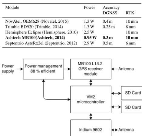
The Ubi is mostly assembled from a number of off-the-shelf components. These include a GNSS receiver module, a mi-crocontroller, an Iridium modem and antenna, a power man-agement unit and GNSS antenna. An overview of the prin-cipal components is given in Fig. 3, and Fig. 4 shows the internal hardware.
Table 1. Comparison of OEM precision GNSS receiver daughter board, values from manufacturer data sheets. The entry marked in bold is the board chosen for use in Ubi.
Module Power Accuracy
DGNSS RTK
NovAtel, OEM628 (Novatel, 2015) 1.3 W 0.4 m 10 mm Trimble BD920 (Trimble, 2014) 1.3 W 0.25 m 8 mm Hemisphere Eclipse (Hemisphere, 2010) 2.5 W 10 mm Ashtech MB100(Ashtech, 2014) 0.95 W 0.3 m 10 mm Septentrio AsteRx2el (Septentrio, 2012) 2.9 W 0.5 m 6 mm
Figure 3. Diagram of receiver principle components.
on-board Real-Time Kinematic (RTK) position modes) and power consumption of five OEM receivers (values from their respective data sheets).
Other GNSS receiver units exist that can record data from the GLONASS, Galileo and BeiDou satellite constellations as well as GPS. These may be appropriate for future versions of Ubi as the coverage of these constellations increases, but for now we rejected these receivers due to their increased power consumption.
After having evaluated available GNSS receiver boards, we decided to build the Ubi around the Ashtech MB100 L1/L2 GNSS receiver board. The MB100 was chosen over others for its low power consumption and lower cost, while at the same time having similar accuracy as other boards (see Table 1).
The Ubi is built around a microcontroller (Micro-Robotics VM2, MicroRobotics, 2015, D040) which is responsible for configuring the GNSS receiver, managing its power supplies, monitoring its performance and logging the raw, unprocessed GNSS data to an SD card. The microcontroller is also re-sponsible for organising the transmission of the Ubi status messages and processing reconfiguration commands via an Iridium 9602 modem (Iridium, 2014, 27000 V3).
As past experience has shown SD cards to be a significant source of unreliability, dual SD card slots are provided for increased reliability. At any given time data are written to only one of those cards. If data-write failure is detected, the system automatically switches to the other memory card.
Figure 4. Internal hardware of Ubi.
2.1 Configuration options
The Ubi is configured by storing a simple, text-based con-figuration file on the SD card. Without such a file, the Ubi will use default configuration values. We have deliberately kept the programming of the units as simple as possible with-out limiting their intended use. As our system is intended for long-term recording of GNSS data and subsequent postpro-cessing only, there is no need for any programming options related to any other uses. This greatly simplifies the use and the programming of the system. At present there are only three configuration variables that need to be set:
1. the duration within each 24 h period (synchronised at midnight) over which the Ubi records GNSS data (0– 24 h, default 24; it will spend the rest of the time in a low-power idle mode);
2. the frequency of status update transmissions via the Irid-ium link, back to the user (1–365 days between mes-sages, default 1 day); and
3. the raw GNSS sample rate (1–300 s).
The raw GNSS data are stored in a compressed ATOM format (Artushkin et al., 2008) which is simple to convert to standard RINEX formatted files.
2.2 Remote interface
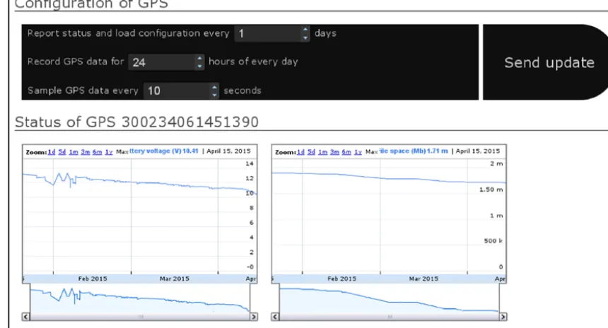
An Iridium modem provides a two-way data link between the Ubi and the user at a remote location. This is a low bandwidth link that is not intended for transferring the large GNSS data sets but for supervision and reconfiguration purposes only. Regular updates from the Ubi describe its configuration, lo-cation, power supply voltage and available file space, details which are displayed or plotted through a website (see Fig. 5). The user can reconfigure the logging period, status update frequency and GNSS sample rate of the Ubi via this same website.
Figure 5. Web interface for remote reconfiguration of the Ubi receiver.
antenna, and is a low cost and low power consuming (45 mA average) modem.
The advantage of this remote reconfiguration capability is the flexibility to respond to changing environmental condi-tions. For instance, if installing large battery packs and wind turbines is impractical, the Ubi can be configured to record for 24 h a day when there is sufficient solar power, or for shorter periods when solar power is insufficient.
The transmitted updates from the Ubi will also give an in-sight into any failures. For instance, if the power supply is failing, it will be evident in the reported battery voltage. If the GNSS antenna or Ashtech modem have failed, it will be evident in the use of file space. Finally, if the Ubi stops trans-mitting updates, the end user can conclude there has been a complete system failure. Based on this information, the end user is better equipped to plan for the next site visit.
2.3 External hardware
Ubi consists of two PCBs that have a conformal coating to protect them from moisture. These are housed in a weather-proof IP67 case (see Fig. 6). Three ports protrude from one end, an SubMiniature version A (SMA) connection for the Iridium antenna port, a threaded Neill–Concelman (TNC) connection for the GNSS antenna port and a four-pin Lemo connector for power and serial communication.
The other end of the case features four LEDs visible be-hind an enclosed window. These enable the end user to quickly validate the correct operation of the power supply, the file system, the GNSS antenna and the Iridium antenna, as well as the Ubi itself. This end is fastened in place with
Figure 6. Ubi case design.
four thumb screws so as to make accessing the SD cards sim-ple.
3 Test results
3.1 Power consumption
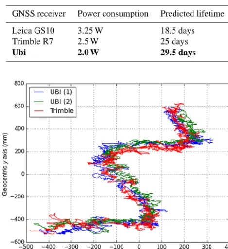
Table 2 compares the power consumption of the Ubi with two commonly used COTS GNSS receivers. The power con-sumption values listed are measured and include the power needed to supply an active GNSS antenna (Leica AS10). The lifetime figures are an estimate of how long the receiver will operate on two 100 Ah batteries at−30◦C.
record-Table 2. Comparison of GNSS receiver power consumption. Bold values highlight the specification of the chosen receiver module.
GNSS receiver Power consumption Predicted lifetime
Leica GS10 3.25 W 18.5 days
Trimble R7 2.5 W 25 days
Ubi 2.0 W 29.5 days
Figure 7. Kinematic tracking of the Brunt ice shelf over the period of 24 h.
ing GPS data. Thus, the Ubi will run for longer when de-ployed with a battery power supply.
Of the 2.0 W power consumed by the Ubi, 0.95 W is for the GPS receiver, 0.35 W is for the GPS antenna and 0.7 W is lost due to power supply voltage conversion. When the status LEDs are active (during the first hour of operation), a further 0.03 W is used, and whenever the iridium transmits data it uses a further 0.95 W.
3.2 Kinematic tracking accuracy
The comprehensive assessment of the accuracy and precision of a GPS receiver is difficult, expensive (Jackson et al., 2000; UNAVCO, 2012; Penna et al., 2012) and subjective; different conclusions can be drawn depending on the form of the ex-periment and the type of post-processing performed. These assessments normally consist of several different measument types, performed on data from one or more of the re-ceivers under evaluation. Here we use three separate types of metrics to evaluate the accuracy of GPS positions calculated from data recorded by Ubi. By themselves, none of these metrics are a conclusive measure of the absolute performance of Ubi but, taken as a whole, their results can be considered indicative of the relative performance of Ubi.
A network of Ubi receivers has been installed next to a Trimble R7 receiver from a different project (Anderson et al., 2013) on the Brunt ice shelf, Antarctica. This ice shelf has a
typical daily vertical tidal movement of 1 m, and the GNSS data were processed with the kinematic precise point posi-tioning (kPPP) technique. We use the GIPSY/OASIS (Zum-berge et al., 1997) GNSS data processing package to perform the kPPP analysis. Figure 7 shows the recorded horizontal movements of three of these receivers, each 20 m apart, from 24 h of data. Two of these receivers were Ubi units (Ubi(1) and Ubi(2)) and one was a Trimble R7 receiver. All were equipped with the same type of GNSS antenna (Leica AS10). The receivers were all attached to a fixed infrastructure, so their relative position did not change. For ease of compari-son between these three receivers, the mean position of each receiver has been subtracted from the displacement curves shown in Fig. 7. As the figure shows, these three displace-ment curves overlap almost perfectly. Hence, the horizontal displacements as determined by these three receivers are al-most identical, and their accuracy therefore comparable.
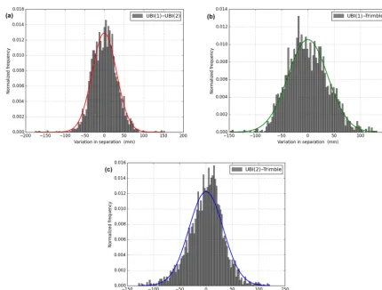
A further insight into the performance and the accuracy of the receivers is gained by calculating the temporal varia-tion in the distances between the receivers, see Figs. 8 and 9. As mentioned above all three receivers were attached to the same platform and the distance between them did therefore not change with time. Calculating the pair-wise distance at each 30 s interval between all the three receivers gives three time series of baseline lengths. We analysed the scatter in those three time series, i.e. the fluctuations in calculated base-line lengths around their respective mean values. Doing so re-vealed that the scatter was smallest for the Ubi(1) to Ubi(2) baseline, and somewhat larger for the two Ubi(1) to Trim-ble R7 and the Ubi(2) to TrimTrim-ble R7, baselines (see Fig. 9). Possibly the smaller scatter in the Ubi(1) to Ubi(2) baseline is simply related to the two Ubi receivers having similar er-ror characteristics resulting in cancellation of erer-rors as the baseline length is calculated, but nevertheless this experiment shows that the Ubi is at least comparable in accuracy to the Trimble R7 GNSS receiver.
3.3 Static position analysis accuracy
This trial was conducted at the British Antarctic Survey head-quarters in Cambridge. An Ubi receiver and a Trimble R7 receiver are installed on the roof with a largely unobstructed view of the sky. Both receivers shared a common choke-ring antenna (Novatel ANT-533) via a two-way powered splitter. The GIPSY/OASIS software was used to generate position estimates and phase residuals. Seven 24 h, 10 s interval files were collected from each receiver. The only change to the de-fault configuration of each receiver was to set the minimum satellite track elevation to be zero degrees.
Figure 8. Histogram of variation in separation between receivers (a) Ubi(1) and Ubi(2), (b) Ubi(1) and the Trimble R7, (c) Ubi(2) and the Trimble R7.
Figure 9. Gaussian fit to temporal variations in pair-wise distances between two Ubi receivers and a third Trimble R7 receiver. The GNSS data from each receiver were processed independently of the data from the other receivers using a kinematic precise point pro-cessing technique (kPPP). All receivers were attached to the same platform (with approximately 20 m separations), and the widths of the Gaussian curves therefore directly reflect baseline errors. As can be seen, the baseline errors are on the order of about 5 cm, an accu-racy expected for short-term kPPP occupation and similar for each receiver pair.
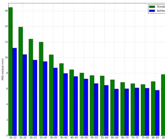
The carrier-phase residuals from each satellite are a mea-sure of the noise in the recorded observations. Figure 10 shows the root-mean-square average of the phase residuals, binned by the calculated angle of elevation of each satellite relative to the receiver in 5◦intervals. Theyaxis is the resid-ual in millimetres. Each bin is a 7-day average of the com-puted L2 band residual. At all elevations the residuals of the Trimble were the highest. This is an indication that the Ubi is the more accurate receiver.
Figure 11 shows the scattering of the positions calculated by GYPSY/OASIS over the same 7-day period. The data are split into both 7×24 h segments and 84×2 h segments prior to processing. The scattering of the positions calculated from 24 h data segments is similar for both receivers, however the outliers from the positions calculated from 2 h segments are all from the Trimble receiver.
3.4 Reliability
Figure 10. Residual analysis measure of accuracy of Ubi and Trimble receivers in Static mode.
Figure 11. Comparison of accuracy of Ubi (Ashtech) and Trimble receivers in static mode.
cards. (These tests were conduced in conjunction with Do-minic Wilson, at Cambridge Data Recovery.) In total, 10 non-functioning SD cards were used, three suffering from soft-ware malfunctions, and the remaining seven from hardsoft-ware malfunctions. Of the three cards with software malfunctions, Ubi correctly detected the fault and switched to use the al-ternate SD card. Of the seven cards with hardware malfunc-tions, Ubi operated correctly for five of them. The two cards
for which it failed were both a low-cost generic brand that failed by saturating the communications bus with the micro-controller. This could be overcome in future versions of Ubi by using a buffered communications bus.
Ultimately, the reliability of the Ubi receivers is best tested through long-term field deployment under realistic condi-tions. Twelve of these Ubi receivers are currently installed in component modules of the Halley VI Antarctic research station. This network of receivers is providing a high quality record of the movement of modules and the overall deforma-tion of the Halley VI stadeforma-tion (Jones and Rose, 2015). The re-ceivers are installed within the station so they are not exposed to harsh polar conditions. These receivers have cumulatively recorded 2 years worth of data without failing.
Furthermore, two prototype receivers were installed in February 2014 outside the Rothera Antarctic research sta-tion. These receivers successfully recorded 3 months of data each before their common power supply failed. Upon re-trieval, the receivers were found to be intact and fully op-erational.
3.5 Benefits of the Ubi receivers
The lower power consumption of the Ubi receivers as com-pared to other typically deployed commercial systems al-lows for substantially smaller power-supply systems to be used. When deploying a system using aircraft, where the to-tal weight of the system is often the limiting factor affecting the design of a GNSS network, the resulting weight reduction can have important consequences.
As an example, in January 2013 we set out to install three commercial GNSS receivers on Institute glacier (81◦S, 76◦W), Antarctica, in a single Twin Otter aircraft flight. Two power systems were designed for this installation: a summer-only system weighing 140 kg and a full-year system weigh-ing 410 kg. Under BAS safety criteria, our aircraft can take off from and land on snow runways with a maximum payload of 2200 kg. Of this payload 250 kg were passengers, and as the nearest fuel depot was 245 km away we needed 1250 kg of fuel, allowing for a potential 700 kg of cargo. Thus, we were able to install no more than one full-year system and two summer-only systems. Had we used the Ubi receiver in-stead of commercial GNSS systems, we could have installed a greater number of such units under the same logistical con-straints. Furthermore, the remote programming capability of the Ubi system would have allowed us to make better use of the available power. For example, using the same summer-only power system, Ubi could have be programmed to log an estimated 8 h of each day during the winter (derived from Table 2) and then to switch to a 24 h logging mode during the summer. If this setup had been available in 2013 we would have had the payload capacity necessary to install four Ubi receivers instead of three, still allowing for the extra fuel needed for a fourth site visit.
4 Conclusions
We have developed, tried and tested a new GNSS receiver specifically designed for long-term deployments in polar ar-eas under harsh conditions. Our GNSS receiver, Ubi, uses less power than existing commercial GNSS receivers, reduc-ing the necessary batteries, solar panels and wind turbines needed for long-term GNSS monitoring. The external in-terfaces of Ubi are common to those of existing GNSS re-ceivers, so installation of Ubi does not require significant changes to existing setup procedures.
The system allows for a two-way communication via an Iridium link. The status of the Ubi receiver is broadcast, and the unit can be reprogrammed remotely. The ability to re-motely reconfigure the Ubi logging period in response to the availability of solar power creates further opportunities to re-duce the size and weight of these power system components. The individual components of a single Ubi receiver can be procured for less than GBP 2000, making this potentially significantly cheaper than commercial alternatives.
The Ubi receiver is at least as accurate as some commer-cial GNSS receivers commonly used for long-term moni-toring. It is easy to configure and has improved status re-porting features. We have made the Ubi firmware open-source (under the GNU version 2 license) and available at https://github.com/antarctica/UBI. This will allow other po-lar scientists to evaluate, use, adapt and improve upon the design for the benefit of all in the community. It is simple to load the Ubi with new firmware via a serial port interface.
The Ubi receiver has one external serial port interface and has connections for another. It also has connections for gen-eral purpose digital and analogue, inputs and outputs. As such it can be easily adapted to log external data feeds or control power lines based on commands triggered by a timer or the Iridium lin.
Acknowledgements. This study is part of the British Antarctic Survey Polar Science for Planet Earth Programme. It was funded by The Natural Environment Research Council (NE/1007156/1).
Edited by: M. Zribi
References
Anderson, R., Jones, D. H., and Gudmundsson, G. H.: Hal-ley Research Station, Antarctica: calving risks and monitor-ing strategies, Nat. Hazards Earth Syst. Sci., 14, 917–927, doi:10.5194/nhess-14-917-2014, 2014.
Artushkin, I., Boriskin, A., and Kozlov, D.: ATOM: Super Compact and Flexible Format to Store and Transmit GNSS Data, Proc ION GNSS, 1895–1902, 2008.
Ashtech: Ashtech MB100 Compact, Low-Power, GPS/GLONASS, RTK OEM Receiver Module, available at: http://intech.trimble. com/library/DS_MB100_US.pdf (last access: 22 March 2016), 2014.
Bauguitte, S. J.-B., Brough, N., Frey, M. M., Jones, A. E., Maxfield, D. J., Roscoe, H. K., Rose, M. C., and Wolff, E. W.: A network of autonomous surface ozone monitors in Antarctica: technical description and first results, Atmos. Meas. Tech., 4, 645–658, doi:10.5194/amt-4-645-2011, 2011.
Bevis, M., Wahr, J., Khan, S. A., Madsen, F. B., Brown, A., Willis, M., Kendrick, E., Knudsen, P., Box, J. E., Dam, T. V., Caccamise, D. J., Johns, B., Nylen, T., Abbott, R., White, S., Miner, J., Fors-berg, R., Zhou, H., Wang, J., Wilson, T., Bromwich, D., and Fran-cis, O.: Bedrock displacements in Greenland manifest ice mass variations, climate cycles and climate change, P. Natl. Acad. Sci. USA, 109, 11944–11948, 2012.
Dach, R., Beutler, G., and Gudmundsson, G. H.: Analysis of GPS Data from An Antarctic Ice Stream, IAG Symp., 133, 569–579, 2008.
Hemisphere: Eclipse II GNSS OEM Module, available at: http: //www.navtechgps.com/assets/1/7/EclipseII_OEM_DS.pdf (last access: 22 March 2016), revision 9/10, 2010.
Jackson, M., Meertens, C., Andreatta, V., and Hove, T. V.: GPS Receiver and Antenna Testing Report for SumoiNet, UNAVCO Knowledgebase, available at: https://facility.unavco.org/science_ tech/dev_test/publications/suominetreportv_4.pdf (last access: 22 March 2016), 2000.
Jones, D. and Rose, M. C.: Measurement of Relative Position of Halley VI modules (MORPH): GPS monitoring of building de-formation in dynamic regions (under review), Cold regions Sci-ence and Technology, 120, 56–62, 2015.
King, M. A., Padman, L., Nicholls, K., Clarke, P. J., Gudmundsson, G. H., Kulessa, B., and Shepherd, A.: Ocean tides in the Wed-dell Sea: New observations on the Filchner-Ronne and Larsen C ice shelves and model validation, J. Geophys. Res.-Oceans, 116, c06006, doi:10.1029/2011JC006949, 2011.
Micro-Robotics: VM2 Datasheet, available at: www.microrobotics. co.uk (last access: 22 March 2016), D040, 2015.
Nettles, M., Larsen, T. B., Elósegui, P., Hamilton, G. S., Stearns, L. A., Ahlstrøm, A. P., Davis, J. L., Andersen, M. L., de Juan, J., Khan, S. A., Stenseng, L., Ekström, G., and Forsberg, R.: Step-wise changes in glacier flow speed coincide with calving and glacial earthquakes at Helheim Glacier, Greenland, Geophys. Res. Lett., 35, L24503, doi:10.1029/2008GL036127, 2008. Novatel: Next Generation High Performance GNSS Receiver,
available at: http://www.novatel.com/assets/Documents/Papers/ OEM628.pdf (last access: 22 March 2016), version 13, 2015. Penna, N., Clarke, P., Edwards, S., and King, M.: Further testing
of commercial Network RTK GNSS services in Great Britain (NetRTK-2), The Survey Association presentation, available at: https://communities.rics.org/gf2.ti/f/200194/7087237.1/PDF/-/ UK_industry_research__Network_RTK_GNSS_Report_2012_ LR.pdf (last access: 22 March 2016), 2012.
Rose, M. C., Maxfield, D., and Junyent, J.: Performance of some environmental power systems in Antarctica, Proceedings of Eu-ropean Geophysical Union, 11, EGU2009–9612, 2009. Septentrio: AsteRx2el GNSS Dual-frequency L-Band Receiver,
available at: http://westlat.com/wp-content/uploads/2012/08/ AsteRx2eL.pdf (last access: 22 March 2016), 2012.
Shepherd, A., Hubbard, A., Nienow, P., King, M., McMillan, M., and Joughin, I.: Greenland ice sheet motion coupled with daily melting in late summer, Geophys. Res. Lett., 36, L01501, doi:10.1029/2008GL035758, 2009.
Tregoning, P., Twilley, B., Hendy, M., and Zwartz, D.: Monitoring Isostatic Rebound in Antarctica with the Use of Continuous Re-mote GPS observations, GPS Solutions, 2, 70–75, 1999. Trimble: TRIMBLE BD920-W3G, available at: http:
//intech.trimble.com/library/DS_BD920-W3G_US.pdf (last access: 22 March 2016), 2014.