doi:10.3926/jiem.2009.v2n2.p337-359 ©© JIEM, 2009 – 2(2): 337-359 - ISSN: 2013-0953
IDEF method-based simulation model design and
development
Ki-Young Jeong
1, Lei Wu
2, Jae-Dong Hong
31
Engineering Management Program at University of Houston-Clear Lake (USA);
2Software Engineering
at University of Houston-Clear Lake (USA);
3Industrial Engineering Tech at South Carolina State
University (USA)
[email protected]
;
[email protected]
;
[email protected]
Received May 2009 Accepted August 2009
doi:10.3926/jiem.2009.v2n2.p337-359 ©© JIEM, 2009 – 2(2): 337-359 - ISSN: 2013-0953
IDEF method-based simulation model design and development
Keywords:
IDEF0, IDEF3, IDEF1X, discrete event simulation, business process
1 Introduction
doi:10.3926/jiem.2009.v2n2.p337-359 ©© JIEM, 2009 – 2(2): 337-359 - ISSN: 2013-0953
The process description methods could play an important role in the simulation requirement collection phase. Although many process design, analysis and modeling (DAM) methods have been developed, using these methods in isolation – non-methodological approach – often fails to capture critical system behaviors due to the complexities and component interactions within the system. A methodological approach – systematic usage of a suite of methods – has a greater chance of success at representing critical system behaviors since it can account for diverse aspects of DAM activities such as information, function, and process interactions by a systematic and integrated usage of methods. IDEF (Integrated DEFinition) is a suite of descriptive modeling methods within which several different modeling languages are defined to describe systems from different perspectives. First, since IDEF is a well defined suite, it is considered to be easier to implement a methodological approach with the IDEF suite rather than with a completely different set of methods. Second since it is a descriptive modeling method, it could easily abstract and capture the essence of the system. In a typical simulation project, a project team consists of many team members such as system analysts, developers and domain experts. The system analysts collect and refine requirements with assistance from domain experts. This is an iterative communication process among all members. The ‘descriptiveness’ of IDEF methods could make this communication process easier and smoother than any other non-descriptive methods. For these reasons, IDEF methods have been a continued research subject.
doi:10.3926/jiem.2009.v2n2.p337-359 ©© JIEM, 2009 – 2(2): 337-359 - ISSN: 2013-0953
IDEF method-based simulation model design and development
which could serve as a base representation for an information model. This paper covers both the second and the third category together. It is an extension of Cho et al. (1999), KBSI (1995), and Chen et al. (2004) in that it attempts to provide an integrated framework of IDEF method-based simulation model design and development to help a successful simulation project.
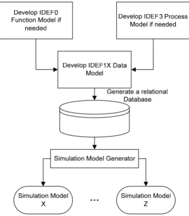
Figure 1. “Conceptual framework of IDEF-based integrated approach”
doi:10.3926/jiem.2009.v2n2.p337-359 ©© JIEM, 2009 – 2(2): 337-359 - ISSN: 2013-0953
IDEF1X, a simulation model is generated with a database-driven simulation model generation approach (DBSMGA). In this framework, the IDEF1X model works as a software independent knowledge base where different simulation software could access to generate models using their libraries. The framework is explained in Figure 1.
This framework is claimed to have the following advantages over non-methodological approaches:
It facilitates knowledge reusability among different modeling methods
during requirement collection phase.
It can capture diverse aspects of real systems from different perspectives,
which improve the accuracy of representation.
It improves simulation model maintainability since the simulation logic can
be changed inside the database as opposed to inside the simulation model.
However, it should be noted that authors do not find it necessary to use this framework for all situations. Instead, this paper claims that this framework has a better chance to lead a successful simulation project by improving communication and knowledge and model reusability. For example, simulation models may be directly built using an icon-based drag-and-drop approach if analysts have sufficient simulation software knowledge. However, based on authors’ experience, this direct model building practice without any methodological approach often generates incorrect models due to the lack of communication, improper model abstraction, and inappropriate model management techniques. Particularly, in a large-scale simulation project, it tends to add more difficulty to the proper simulation project management.
2 IDEF Methods for Business Process Knowledge Capture
According to Lin et al. (2002), a business process has the following elements:
A business process has its customers.
A business process is composed of activities whose objectives are to create
doi:10.3926/jiem.2009.v2n2.p337-359 ©© JIEM, 2009 – 2(2): 337-359 - ISSN: 2013-0953
IDEF method-based simulation model design and development
Activities are performed by actors who may be humans or machines
A business process often involves organizational units which are responsible
for the whole process.
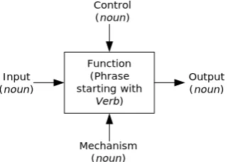
We believe that IDEF methods well support those elements. For example, IDEF0 was designed to capture the ‘decisions’ and ‘activities’ of a system (Mayer et al., 1995). Those decisions and activities include information on what functions the system performs, what constraints the functions have, what is needed for functions, and what input and output are meaningful in performing those functions. An IDEF0 model is represented with rectangles with four different types of arrows surrounding the rectangles. A rectangle represents a function or activity described in a verbal phrase, and arrows represent (1) “Input” (on the left); (2) “Output” (on the right); (3) “Control” (on the top); and (4) “Mechanism” (on the bottom) called (ICOM) described in a noun phrase to explain the behavior of the function – see Figure 2 below. It also supports the hierarchical decomposition of activities for an appropriate abstraction of a system. We notice that the first three business elements could be supported by IDEF0. For example, IDEF0 model could be developed from a specific customer’s perspective and context – first element. The business activities are part of system activities – second element. The mechanism in ICOM includes actors – third element.
Figure 2. “IDEF0 function modeling notation”.
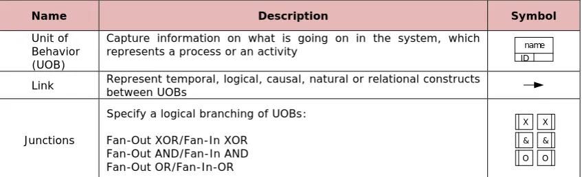
IDEF3 is a process capture and description method within the context of a specific scenario (Mayer et al., 1995). The process schematic of IDEF3 has been widely accepted as a medium for process description in industry (Mo et al., 1998). As seen in Figure 3, the process schematic consists of the three main components: (1) “Unit Of Behavior” (UOB); (2) “Junction”; (3) “Link”.
Function (Phrase starting with
Verb) Control (noun)
Output (noun) Input
(noun)
doi:10.3926/jiem.2009.v2n2.p337-359 ©© JIEM, 2009 – 2(2): 337-359 - ISSN: 2013-0953
Name Description Symbol
Unit of Behavior (UOB)
Capture information on what is going on in the system, which represents a process or an activity
ID name
Link Represent temporal, logical, causal, natural or relational constructs between UOBs
Junctions
Specify a logical branching of UOBs:
Fan-Out XOR/Fan-In XOR Fan-Out AND/Fan-In AND Fan-Out OR/Fan-In-OR
Figure 3. “IDEF3 process schematics”.
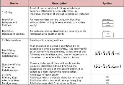
A UOB captures information on what is going on in a system to represent a process or an activity. It is depicted by a rectangle with a unique label. Junctions provide a mechanism specifying a logical branching of UOBs and introduce the timing – temporal – and sequencing of multiple processes. Junction types include an exclusive OR denoted by “X”, a conjunctive AND junction denoted by “&”, and an inclusive OR denoted by “O”. Since IDEF3 uses a scenario as a basic organization structure to describe how things work, it could easily fit with the first three elements of a business process. It also supports the top-down and bottom-up modeling sequences and hierarchical decomposition for multiple levels of abstraction. IDEF1X produces a data model that represents the structure and semantics of information within an enterprise or a system, known as business rules. An IDEF1X diagram is refined into three levels of detail: (1) an entity-relationship level; (2) a key-based level; (3) an attribute level. Diverse business rules are specified according to different levels of detail, and the model development is defined by these three level modeling procedures. Figure 4 shows summary of these three levels with symbols. Interested users are encouraged to read (KBSI, 1994) for detailed grammar and graphical symbols for the IDEF1X method.
Lin et al. (2002) also identified ten essential concepts useful in defining a business process, and we creatively used these concepts to investigate the fitness of the proposed IDEF method-based integrated framework for business process simulation model design and development. The results are summarized in Table 1. This table shows all but one concept are handled and represented by this framework.
X X
& &
doi:10.3926/jiem.2009.v2n2.p337-359 ©© JIEM, 2009 – 2(2): 337-359 - ISSN: 2013-0953
IDEF method-based simulation model design and development
Name Description Symbol
1) Entity
A set of real or abstract things which have common attributes or characteristics. An
individual member of the set is called an instance
Identifier-Independent Entities
An instance that can be uniquely identified without determining its relationship to another entity
Entity Name key Attribute
Identifier-Dependent Entities An instance whose identification depends on its relationship to another entity.
Entity Name key Attribute
2) Relationships Relationship among entities
Identifying Connection Relationships
If an instance of a child is identified by its association with a parent entity, it is referred to as an identifying relationship. It has one of the following cardinalities (zero, one or more/one or more/zero or one/exactly n/from n to m)
/
( P/ Z/ n/ n-m)
Non-Identifying Connection Relationships
If every instance of the child entity can be uniquely identified without knowing the associated instance of the parent entity, it is called as a non-identifying relationship.
/
( P/ Z/ n/ n-m)
3) Keys Attributes of each entity
Primary Keys Attributes which uniquely identifies an entity (PK) Alternate Keys Attributes which can work as a primary key (AK) Foreign Keys Attributes migrated from other entities (FK)
Figure 4. “IDEF1X building blocks and symbols”.
Concepts Descriptions IDEF0 IDEF3 IDEF1X
Activity Task, function or operation
Behavior Action, business rules or control
Resource Mechanism or location
Relation Relation class, junctions and links, interaction, and dependencies
Agent Social actor or role
Information Message
Entity Object represented by attributes
Event Represented by as event objects or inputs/outputs
Verification and
validation Model built as intended? Model well represents reality? Modeling
procedure Specific procedures to build a model
Table 1. “Business concepts vs. IDEF methods”.
doi:10.3926/jiem.2009.v2n2.p337-359 ©© JIEM, 2009 – 2(2): 337-359 - ISSN: 2013-0953
3 IDEF1X Data Model Knowledge Base for Simulation Model
An IDEF1X data model should be robust enough to make the structural and semantic aspects of the simulation included in the model. One way to consider the semantic aspects of the simulation model is to study the simulation ontology, and reflect it within the data model design, since ontology provides the definition of the terminologies and relationship between them. Although several DES software packages are available in the market, they have some common basic structures or objects, while the unique structures are variations of these common structures. If a data model incorporates these structures into its design, it could be shared by different DES software packages.
Table 2 lists some of these basic common structures with their definitions within the context of business process simulation. Note that the neutral terminologies,
Generator, Entity, Location, Resource, Queue, and Destroyer are used to avoid
favoring a particular simulation language. For example, ED (2001) uses Source, Product, Server or Multiple-Service, Operator, Queue, and Sink while Flexsim (2007) uses Source, FlowItem, Processor or Multiprocessor, Operator, and Sink instead of these neutral terminologies.
Name Definition
Generator A structure that creates entities to populate a model
Entity A structure that flows through the model to represent customers, orders and any moving items in the model.
Location A structure that interacts with an entity. This interaction is called a service, and it usually delays the progress of an entity through the model.
Resource A structure that may be required by an entity or a location to provide a service. The difference between a location and a resource is that a location does not move, and a resource is moving toward a location when it is requested.
Queue A structure that stores entities. The queue is awaiting service, not receiving service. Destroyer A structure that destroys entities
Table 2. “Basic simulation objects and definition”.
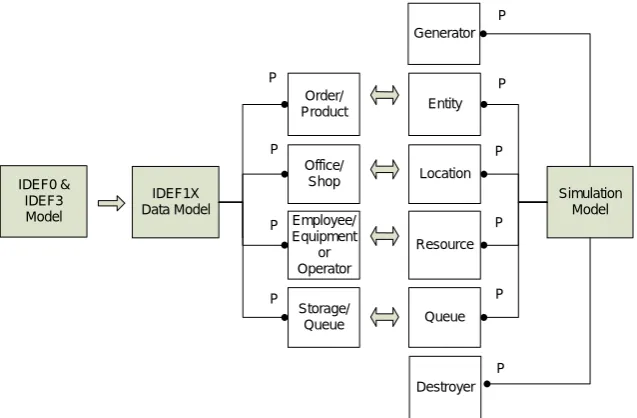
Figure 5 shows one possible mapping between an IDEF1X data model and corresponding neutral simulation structures (objects). The data model has multiple – one or more, denoted by P – Order/Product, Office/Shop, Employee/Equipment or Operator, and Storage/Queue objects. Each of which is mapped to Entity,
Location, Resource and Queue object, respectively, in the simulation model. Note
doi:10.3926/jiem.2009.v2n2.p337-359 ©© JIEM, 2009 – 2(2): 337-359 - ISSN: 2013-0953
IDEF method-based simulation model design and development
Once a data model is built with consideration of simulation structures, the database can be easily created from which multiple simulation models could be automatically developed.
Figure 5. “Simulation and data model mapping”.
From a simulation perspective, the data model characterizes the required functionalities of simulation libraries. Hence if those functionalities are not supported by specific target simulation software, those functionalities should be developed to make the database-driven simulation model development easier.
4 Database-Driven Simulation Model Development
Most simulation software provides its own script language with structured query language (SQL) and Open Database Connectivity (ODBC) capability. Hence, the interface between the simulation and database management system (DBMS) becomes easier but it still requires some coding efforts. In this study, both Flexsim and ED libraries were adopted to implement DBSMGA since both provide the Object-Oriented customized library development capability in addition to the rich standard libraries. The customized library development capability is supported using Flexscript (Flexsim’s script language) or C/C++ in case of Flexsim and 4D Scripts in case of ED. Each object (library) consists of a set of attributes (characteristics) and methods (functions) that can be implemented when an associated event handler is activated in the library. In case of Flexsim, some typical examples of an event handler are OnReset – triggered when users click the
IDEF1X Data Model
Simulation Model P
P
Employee/ Equipment
or Operator
Storage/ Queue Order/ Product
Office/ Shop
Entity
Resource
Queue Location Generator
Destroyer P
P P
IDEF0 & IDEF3 Model
P
P
P
P
doi:10.3926/jiem.2009.v2n2.p337-359 ©© JIEM, 2009 – 2(2): 337-359 - ISSN: 2013-0953
reset button, OnMessage – triggered when an object receives a message from other objects, OnEntry – triggered when an entity enters current object, and OnExit – triggered when an entity leaves from a current object. All properties of a class are inherited to the instances of the class when they are created in a model. By combining the standard library and the customized library, users can develop their own user-specific and/or domain-specific simulation software, which makes mapping from the data model to the simulation easier.
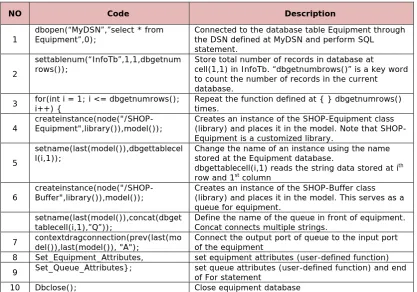
In the case study to be discussed later, we first developed a Flexsim model. A customized library named “simulation-generator” was developed to generate simulation models from a database. Note that this corresponds to the Simulation Model Generator in Figure 1. All codes were written in the User event handler and the total lines of the codes are less than 250 including all user-interface and screen embellishment.
NO Code Description
1 dbopen(“MyDSN”,”select * from Equipment”,0); Connected to the database table Equipment through the DSN defined at MyDSN and perform SQL statement.
2
settablenum(“InfoTb”,1,1,dbgetnum
rows()); Store total number of records in database at cell(1,1) in InfoTb. “dbgetnumbrows()” is a key word to count the number of records in the current database.
3 for(int i = 1; i <= dbgetnumrows(); i++) { Repeat the function defined at { } dbgetnumrows() times.
4 createinstance(node("/SHOP-Equipment",library()),model()); Creates an instance of the SHOP-Equipment class (library) and places it in the model. Note that SHOP-Equipment is a customized library.
5
setname(last(model()),dbgettablecel
l(i,1)); Change the name of an instance using the name stored at the Equipment database. dbgettablecell(i,1) reads the string data stored at ith row and 1st column
6 createinstance(node("/SHOP-Buffer",library()),model()); Creates an instance of the SHOP-Buffer class (library) and places it in the model. This serves as a queue for equipment.
setname(last(model()),concat(dbget
tablecell(i,1),”Q”)); Define the name of the queue in front of equipment. Concat connects multiple strings. 7 contextdragconnection(prev(last(model()),last(model()), "A"); Connect the output port of queue to the input port of the equipment 8 Set_Equipment_Attributes, set equipment attributes (user-defined function) 9 Set_Queue_Attributes}; set queue attributes (user-defined function) and end of For statement
10 Dbclose(); Close equipment database
Table 3. “Partial pseudo code in simulation model generator”.
Table 3 shows the partial pseudo-codes to create instances of a library object from
Equipment table to explain how to read the database through ODBC (lines 1 and
doi:10.3926/jiem.2009.v2n2.p337-359 ©© JIEM, 2009 – 2(2): 337-359 - ISSN: 2013-0953
IDEF method-based simulation model design and development
(lines 2-9). One record in Equipment table represents one machine instance whose field consists of (equipment ID, equipment Name, Capacity, MTBF, MTTR etc). Lines 8 and 9 are calling user-defined functions to define the attributes of all instances. It is important to recognize that a model is a set of instances of all classes (or objects) located in the library. These classes may be provided by vendors or newly created by users. In this study, the “SHOP-Equipment” object and “SHOP-Buffer” object were created in the library by authors using Flexscript to facilitate the mapping from the data model to Flexsim.
5 Guidelines for Knowledge Reusability among IDEF methods
Developing a descriptive model using IDEF methods requires a feedback loop for obtaining consensus and confirmation from domain experts. Considering the fact that each IDEF uses a different modeling language to capture different perspectives of the real systems, the captured knowledge reuse among different IDEF methods has proven difficult to generalize. However, the importance of the knowledge reuse is critical – remember 40-40-20 rule, and how much time is required for requirement collection and experimentation? Based on our experience, the following guidelines seem to be useful in the knowledge reuse among IDEF0, IDEF3 and IDEF1X. As stated previously, IDEF0 represents the functional behavior of a system through four different types of data (ICOM) and a set of activities. The ICOM data could be information, objects or anything described in a noun phrase. Hence, some of the IDEF0 data may be represented as an object or an attribute in the IDEF1X model. Although IDEF0 is not designed to capture the temporal relationship among activities, some functional aspects of the system may include the temporal relationship among activities. Hence, if this happens, some activities in IDEF0 could be also represented in the IDEF3 diagram. Guidelines recommended for knowledge reusability among IDEF methods include:
An IDEF0 modeling is recommended first since it provides overall system
level knowledge.
Then, an IDEF3 modeling is recommended if temporal information among
doi:10.3926/jiem.2009.v2n2.p337-359 ©© JIEM, 2009 – 2(2): 337-359 - ISSN: 2013-0953
With help of IDEF0 and IDEF3, the detailed IDEF1X model could be
developed.
A “Mechanism” in IDEF0 may easily turn out to be an object in IDEF1X since
“Mechanism” often includes resources – a typical object in an IDEF1X model.
The “Constraint” in IDEF0 may provide a logical object in IDEF1X since this
“Constraint” often represents the business rules of a system.
Check if there is any noun in the verbal phrase (function) in an IDEF0 model
that needs to be translated into an attribute or object in an IFED1X model. Since a verbal phrase explains the behavior of the function, some nouns used in the phrase may convey meaningful information for a data model.
6 Case Study
doi:10.3926/jiem.2009.v2n2.p337-359 ©© JIEM, 2009 – 2(2): 337-359 - ISSN: 2013-0953
IDEF method-based simulation model design and development
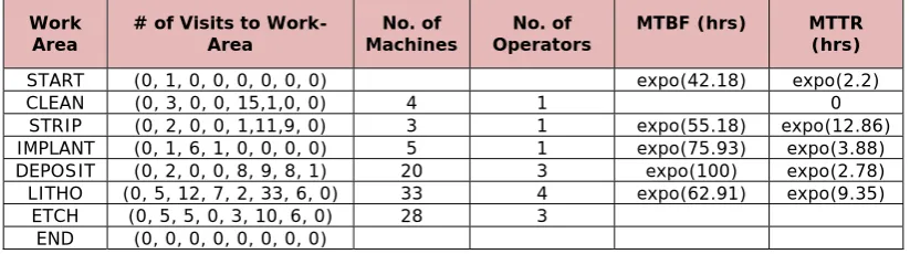
that both MTBF and MTTR are exponentially distributed, denoted by expo(). Two virtual areas were added to indicate the starting (START) and ending (END) of the process. Note that the second column consists of 8-tuples and each of which denotes the number of visits to each work-area. This 8-tuples are arranged in the orders of START, CLEAN, STRIP, IMPLANT, DEPOSIT, LITHO, ETCH and END. It is assumed that this shop is operating for 24 hours with 3 eight-hour shifts due to high capital equipment. The main performance measure for this shop is the system cycle time.
Work
Area # of Visits to Work-Area Machines No. of Operators No. of MTBF (hrs) MTTR (hrs)
START (0, 1, 0, 0, 0, 0, 0, 0) expo(42.18) expo(2.2)
CLEAN (0, 3, 0, 0, 15,1,0, 0) 4 1 0
STRIP (0, 2, 0, 0, 1,11,9, 0) 3 1 expo(55.18) expo(12.86) IMPLANT (0, 1, 6, 1, 0, 0, 0, 0) 5 1 expo(75.93) expo(3.88) DEPOSIT (0, 2, 0, 0, 8, 9, 8, 1) 20 3 expo(100) expo(2.78) LITHO (0, 5, 12, 7, 2, 33, 6, 0) 33 4 expo(62.91) expo(9.35)
ETCH (0, 5, 5, 0, 3, 10, 6, 0) 28 3 END (0, 0, 0, 0, 0, 0, 0, 0)
Table 4. “Facility data by work-area”.
doi:10.3926/jiem.2009.v2n2.p337-359 ©© JIEM, 2009 – 2(2): 337-359 - ISSN: 2013-0953
Load a Job to a Machine
Set Up a Machine
WIP
Perform an Operation selected job
Unload a Job Available
Jobs Select a Job to
Operate loaded job
finished job
unloaded job
Operator Machine
Dispatching Rule
Machine Operation Recipe
Lot No identity Transfer Batch Size
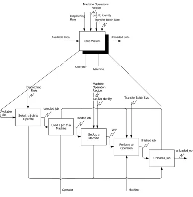
Figure 6. “Function model of a fabrication process in strip area”.
doi:10.3926/jiem.2009.v2n2.p337-359 ©© JIEM, 2009 – 2(2): 337-359 - ISSN: 2013-0953
IDEF method-based simulation model design and development
constraint called Machine Operation Recipe, which may contain the operation sequence information for each product.
With the help of IDEF0 model and the problem descriptions, the IDEF1X model is defined as in Figure 7. Based on above discussions associated with the IDEF0 model, the Equipment, Product, Operator and DispatchRule are first defined as an independent object (entity) with keys and attributes. For example, each equipment needs capacity, MTBF, MTTR, setup time and run time, WorkingShift, Overtime,
BufferSize and Dispatching_ID information. The BufferSize defines the size of
buffer in front of an equipment holding parts awaiting processing, and the
Dispatching_ID is the set of rules defining the sequence of jobs in the queue.
Typically, it follows FIFO – First-In-First Out. In this case study, the queue object represented in Table 2 is not handled as a separate object since all queues in front of each piece of equipment are considered as infinite.
Operator Operator_ID Desc Capacity SkillCode WorkingShift OverTime P Product_ID (FK) Equipment_ID (FK) Operator_ID (FK) EquipSetupTime EquipRunTime LaborSetupTime LaborRunTime Operation_Code (AK) Desc Operation P P Routing Routing_ID Product_ID (FK) Operation_Code_From Operation_Code_To Percentage P Equipment Name Capacity MTBF MTTR SetupTime RunTime WorkingShift OverTime BufferSize Dispatching_ID (FK) Product Product_ID Name Demand LotSize Quantity in Parent Parent ID DispatchRule Dispatching_ID Desc P Equipment_ID
Figure 7. “IDEF1X data model for case study”.
The Product object can represent a bill-of-material (BOM) information through
Quantity in Parent and Parent ID attributes. The demand and LotSize are attributes
doi:10.3926/jiem.2009.v2n2.p337-359 ©© JIEM, 2009 – 2(2): 337-359 - ISSN: 2013-0953
It is important to understand the difference between the Operation and the Routing object. The Operation contains all operation information that describes “who (operator) handles what products with what machines for what time”, and the
Operation_Code can be used as an alternative primary key. The Routing object is
created for simulation model generation to describe the sequence of operations for each product using the information in an Operation object. For each product type (non-primary FK), the source operation code (OperationCode_From) and the destination operation code (OperationCode_To) is described with its corresponding routing probability (Percentage) to support the probabilistic routing view. The
Routing object provides the sequence of operations for each product type while
these operations are characterized by the Operation object. The prototype data
model in Figure 7 was translated into the corresponding MS-ACCESSTM database
using the SmartERTM case tool developed by KBSI (1994). Figure 8 shows a
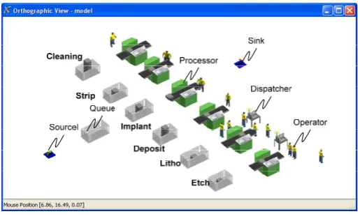
snapshot of the Flexsim simulation model generated from the data model in Figure 7 using the codes in “simulation-generator” library whose partial pseudo-codes are represented in Table 3.
Figure 8. “A snapshot of Flexsim model from database”.
doi:10.3926/jiem.2009.v2n2.p337-359 ©© JIEM, 2009 – 2(2): 337-359 - ISSN: 2013-0953
IDEF method-based simulation model design and development
denoted by “1” represents a product atom corresponding to the Product object in Figure 7. The queue atom denoted by “2” has infinite capacity, which corresponds to a Buffer object. The operation atom denoted by “3” contains all equipment information such as MTBF and MTTR as its attributes, and it also includes all sub-operations such as loading, set up, cleaning operation and unloading operation.
C L E A N
S T R IP
IM P L A N T
D E P O S IT
L IT H O
E T C H
1. P R O D U C T 2 . Q U E U E 3. O P E R A T IO N 4. O P E R A T O R 5. R O U T IN G 6. O P C O N T R O L
Figure 9. “A Snapshot of ED model from database”.
When a sub-operation requires an operator, the atom performing the operation (i.e. cleaning atom) sends an operator-request-message (ORM) to a corresponding operator control atom (OP CONTROL). The operator control atom matches an ORM to an available operator, and it sends available operator(s) to the requesting atom. If there is no available operator for that ORM, it has to wait at the internal message queue inside an operator control atom. Once the (sub) operation finishes, the operator is released from the requesting atom and it becomes available again. All channels are connected using the information in the Routing object, and sub-operation information in an sub-operation atom comes from the Operation object in Figure 7. The operator atom corresponds to the Operator object.
doi:10.3926/jiem.2009.v2n2.p337-359 ©© JIEM, 2009 – 2(2): 337-359 - ISSN: 2013-0953
from the database by changing the “Operator_ID” in the Operation table without modifying any logic in Flexsim environment for different scenarios. The average cycle time and throughput (number of units produced per day) were compared and displayed in Figure 10 where the bar shows the average cycle time and the line represents the throughput. As seen in the figure, the performance of the second alternative (ALT2) is almost identical to that of the first alternative (ALT1) even with less number of operators, and both outperform the third alternative (ALT3).
Figure 10. “Alternative comparison”.
Through this case study, we showed that the IDEF method-based integrated framework could help improve the process of a simulation project by using IDEF-based descriptive models to capture requirements and to perform the experimentation. The IDEF1X-based data model supported by IDEF0 and IDEF3 could reduce the time and effort for simulation model development and maintenance. Before closing this section, it should be recognized again that the DBSMGA does not depend on any specific simulation software. Any simulation software supporting the ODBC and SQL capabilities could be used. If the software has the capability to customize the standard library, it could also reduce the effort required to map the data model into the simulation model.
7 Discussion and Conclusion
In this paper, the integrated framework of IDEF method-based simulation model design and development was provided for a business process. In this framework, the systematic use of IDEF0 and IDEF3 for business processes was proposed to help the requirement collection phase in a simulation project. From this systematic use of both descriptive models, the IDEF1X-based data model was created and became a knowledge base from which multiple simulation models could be developed, which could save time and effort in the experimentation phase in a
34.21 34.72 141.63 2.40 2.40 2.24 2.15 2.20 2.25 2.30 2.35 2.40 2.45 0 20 40 60 80 100 120 140 160
ALT1 ALT2 ALT3
T h ro ug hpu t ( uni ts /d ay ) c y c le t ime ( d ay )
avg cycle time (day)
doi:10.3926/jiem.2009.v2n2.p337-359 ©© JIEM, 2009 – 2(2): 337-359 - ISSN: 2013-0953
IDEF method-based simulation model design and development
simulation project. A case study in a semiconductor manufacturer was conducted to show the feasibility of this framework where both Flexsim model and ED model were generated. This paper also discussed the guidelines to reuse the captured system knowledge among IDEF0, IDEF3 and IDEF1X.
The advantages of this integrated framework are to improve design knowledge reusability among IDEF0, IDEF3 and IDEF1X. It could also significantly reduce simulation model development and maintenance effort. By combining both IDEF methods and the database technologies together, this research significantly improved the previous IDEF based researches in that this framework provided a specific, systematic way to implement and execute the previous IDEF based modeling and design works. Many practitioners and simulation developers have been using the icon-based graphic user interface, and they should be familiar with all icons to develop and use the simulation models – This naturally leads to more focus on the model development phase without the ‘descriptiveness’ for better communication. However, the framework used here could change this game rule. The use of IDEF methods leads to more focus on the requirement collection phase of the simulation project. Also by using database as a knowledge base, this framework eliminated the dependence on the specific simulation software, and increased the efficiency in the experimentation phase of a simulation project. Authors believe that the results will significantly contribute to the successful use of simulation in the business process area where requirement collection is considered most difficult but important. Another direct advantage of this framework is that this could be applied to any analytical model as long as that model supports the database technology by separating the logic from the data.
doi:10.3926/jiem.2009.v2n2.p337-359 ©© JIEM, 2009 – 2(2): 337-359 - ISSN: 2013-0953
model and/or database model could be another direct research area in this category since there may be an optimal data model in a specific domain. In the second category, the direct research area includes the development of an integrated simulation model generator through which the same knowledge in the database is transformed into software specific simulation models. In this way, the knowledge reusability will be maximized among simulation software products. Also, integrating all these – both descriptive modeling methods and the database model – within single platform could also be considered as another promising future research area.
References
Ang, C. L., Luo, M., & Gay, R. K. L. (1994). Development of a knowledge-based manufacturing modeling system based on IDEF0 for the metal-cutting industry.
International Journal of Economics, 34(3), 267 – 281.
Chen, P., Caiyun, W., Tiong, R., Seng, K. T., & Qizhen, Y. (2004). Augmented IDEF1-based process-oriented information modeling. Automation in Construction, 13(6), 735 - 750.
Cho, H., & Lee, I. (1999). Integrated framework of IDEF modeling methods for structured design of shop floor control systems. International Journal of Computer
Integrated Manufacturing, 12(2), 113-128.
Deuermeyer, B. L., Curry, G. L., & Feldman, R. M. (1993). An automatic modeling approach to the strategic analysis of semiconductor fabrication facilities.
Production and Operation Management, 2(3), 195-220.
Enterprise Dynamics. (2001). Reference Guide 4Dscript. Maarssen, The Netherlands.
Flexsim. (2007). Flexsim Simulation Software User Guide Version 4.0, Flexsim Software Products, Inc.
doi:10.3926/jiem.2009.v2n2.p337-359 ©© JIEM, 2009 – 2(2): 337-359 - ISSN: 2013-0953
IDEF method-based simulation model design and development
KBSI. (1994). SmartERTM user’s manual and reference guide Ver. 2.0, Texas,
College Station, Knowledge Based Systems.
KBSI. (1995). ProSimTM Automatic process modelling for Windows: user’s manual
and reference guide ver. 2.1. College Station, TX, Knowledge Based Systems.
Lin, F. R., Yang, M. C., & Pai, Y. H. (2002). A generic structure for business process modeling. Business Process Management Journal, 8(1), 19 – 41.
Lingzhi, L., Leong, A. C., & Gay, R. K. L. (1996). Integration of information model (IDEF1) with function model (IDEF0) for CIM information system design. Expert
Systems With Applications, 10(¾), 373 - 380.
Mayer, R. J., Benjamin, P. C., Caraway, B. E., & Painter, M. (1995). A framework and a suite of methods for business process reengineering, in Grove, V. and Kettinger, W. J. (Ed.), Business Process Change: Reengineering Concepts,
Methods and Technologies, (pp. 245 - 290). London: Idea Group Publishing.
Mo, J. O. T., & Menzel, C., P. (1998). An Integrated Process Model Driven Knowledge Based System for Remote Customer Support. Computers in Industry, 37(3), 171-183.
Pidd, M. (1992). Guidelines for the design of data driven generic simulators for specific domains. Simulation, 59(4), 237 – 243.
Resenburg, A. V., & Zwemstra, N. (1995). Implementing IDEF techniques as simulation modelling specifications. Computers and industrial engineering, 29(1-4), 467-471.
Ryan, J., & Heavey, C. (2006). Process modeling for simulation. Computers in
Industry, 57(5), 437-450.
Sheppard, S. (1983). Applying software engineering to simulation. Simulation
Practice and Theory, 10(1), 13-19.
Zhang, J., Chuah, B., Cheung, E., & Deng, Z. (1996). Information modeling for manufacturing systems: A case study. Robotics & Computer-Integrated
doi:10.3926/jiem.2009.v2n2.p337-359 ©© JIEM, 2009 – 2(2): 337-359 - ISSN: 2013-0953
©© Journal of Industrial Engineering and Management, 2009 (www.jiem.org)
Article's contents are provided on a Attribution-Non Commercial 3.0 Creative commons license. Readers are allowed to copy, distribute and communicate article's contents, provided the author's and Journal of Industrial Engineering and Management's names are included. It must not be used for commercial purposes. To see the complete