Simple Energy-Based Method for Nonlinear Analysis of
Incompressible Pile Groups in Clays
Assaf Klar, Ph.D.
1; and Yat-Fai Leung
2Abstract:This note presents a method for predicting nonlinear response of pile groups in clays, subjected to vertical loads. The method is based on mobilizable strength design共MSD兲concepts, in which the mobilized strength is associated with the shear strains developed in the soil. The suggested procedure is incremental, and requires evaluation of a displacement field. A simple procedure of superposition of pattern functions is suggested for the construction of a complete displacement field. The incremental procedure allows for the variation of the displacement field throughout the loading process, according to principles of minimum energy and compatibility requirements among the piles. Essentially, the procedure allows consideration of a nonlinear continuum between the piles. The pattern functions are an adaptive form of the logarithmic function suggested by Randolph and Wroth in 1979. Under small load levels, when the soil is essentially elastic, the procedure yields values comparable to those from the elastic solution of Randolph and Wroth. At larger strain levels, nonlinear pile group response is simulated based on the soil constitutive models specified by the practitioner. The method is applicable to cases where shaft loading does not induce volume changes in the soil. The method is compared with three dimensional finite difference simulation of undrained loading of pile groups with a nonlinear soil constitutive model. Fair agreement is observed.
DOI:10.1061/共ASCE兲GT.1943-5606.0000002
CE Database subject headings:Pile groups; Pile foundations; Clays; Energy methods; Nonlinear analysis.
Introduction
Pile group analysis methods have been studied extensively over the past few decades. Simple approaches of superposition共Poulos 1968兲 and load transfer functions 共Randolph and Wroth 1979兲 were successfully developed throughout the years for linear elas-tic soil. These methods, however, may not be suitable when soil nonlinearity affects the interaction. To cope with soil nonlinearity, different relaxing assumptions and approaches have been sug-gested.
One of the widely used approaches is based on the assumption that nonlinearity is associated solely with the soil adjacent to the pile 共e.g., Poulos 1989; Basile 1999兲. With this assumption, slip elements are used to limit the contact stresses between the soil and the pile shaft. A different common approach is to use nonlin-ear load transfer functions, usually scaled from a function de-scribing single pile behavior共e.g., O’Neill et al. 1982; Lee and Xiao 2001; Randolph 2003b兲.
The current approach differs from previous works as it does not confine soil nonlinearity to the vicinity of the pile, but con-siders a complete nonlinear continuum in the soil–pile interaction problem. Essentially, the suggested method utilizes mobilizable strength design共MSD兲principles共e.g., Bolton and Powrie 1988;
Osman and Bolton 2005兲. As a variant of the MSD approach, the suggested method is named the extended MSD共EMSD; Klar and Osman 2008兲. Unlike the original MSD, the EMSD approach entails a deformation field that changes throughout the loading process to minimize internal work. The EMSD method was suc-cessfully applied to shallow foundations 共e.g., Klar and Osman 2008兲and to laterally loaded piles共e.g. Klar and Randolph 2008兲. In the current work the method is extended to handle interaction between vertically loaded piles. In the method, the external load and pile group stiffness are obtained by equating the external work with the minimized internal work. The main advantage of the MSD approach lies on its suitability to incorporate general stress–strain curves obtained from shear tests 共conducted on un-disturbed samples兲, and therefore offering a flexible framework to adjust the model according to information obtained from site ex-ploration. The method is not restricted to a single stress–strain relation for the soil, and different regions of the soil mass may be associated with different curves. For example, it is known that stress conditions in the vicinity of the pile can be changed due to the pile installation process, and this can affect the global behav-ior of the pile. The effect of installation may be incorporated into the analysis if the stress–strain curves used in the MSD are ob-tained from soil samples extracted after the installation of the pile. In this case, however, a series of tests, each of which related to a different distance from the pile, should be conducted, and associ-ated with the different regions of the soil mass in the analysis. The current work focuses on groups of incompressible piles under a rigid pile cap which is not in direct contact with the soil.
Formulation
The assumption of Randolph and Wroth共1979兲, which decouples the shaft and base responses, is adopted. Therefore, the global pile
1
Senior Lecturer, Faculty of Civil and Environmental Engineering, Technion–Israel Institute of Technology, Haifa 32000, Israel. E-mail: [email protected]
2
Ph.D. Student, Dept. of Engineering, Univ. of Cambridge, Trumping-ton St., Cambridge CB2 1PZ, U.K.
group response is a combination of the shaft response and the base response
Pt=Ps+Pb 共1兲 wherePt= total load on the pile group;Ps= pile shaft resistance; and Pb= pile base resistance. In reality, the base and shaft re-sponses may be somewhat coupled, but the assumption of Eq.共1兲 following Randolph and Wroth共1978, 1979兲has been shown to be a reasonable approximation for single and pile group analysis. Moreover, it is common in Winkler spring or load transfer ap-proaches to adopt the decoupling assumption. For example, Lee and Xiao共2001兲demonstrated that this decoupling is acceptable even when the pile group behavior is nonlinear.
As in Randolph and Wroth共1978兲, soil deformation around a single pile is represented by shearing of concentric cylinders, whereas the base response is obtained from a rigid punch solu-tion.
An incremental procedure is required to obtain a complete nonlinear response of the pile group. At each stage of the proce-dure, an incremental displacement field is constructed by super-position of the shearing cylinders to obtain the shaft resistance, whereas the base resistance is assumed to be elastic-perfectly plastic. Evaluations of the shaft behavior and the base response are presented separately in the following subsections.
Formulation for the Shaft Response
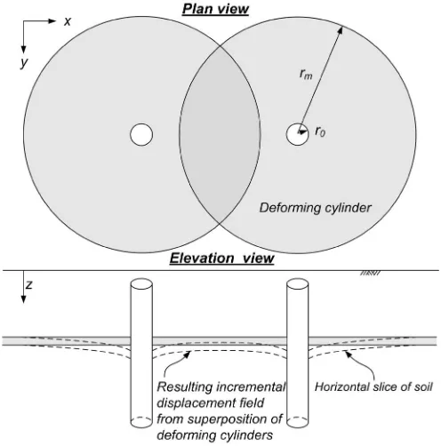
A complete deformation field for a pile group may be obtained by superposition of displacement fields of individual shearing cylin-ders, as illustrated in Fig. 1. Unlike the work of Randolph and Wroth共1978, 1979兲, the extent of the deformation field共shown as rmin Fig. 1兲is not predefined according to some fixed value, but is allowed to change throughout the loading sequence satisfying the requirements of energy minimization.
At each stage of the procedure an incremental displacement field is constructed. For incompressible piles the soil displace-ment may be assumed to be constant along the pile down to the
pile base level, and hence only a unit horizontal slice of soil needs to be considered for evaluating the soil strains associated with the shaft behavior.
The vertical soil displacement in thezdirection共Fig. 1兲can be represented using the following expression:
u˙共x,y兲=
兺
i=1 N␣ifs共sxyi ,rmi兲␦˙
fs共sxy i
,rm i兲
=
冦
1, sxyi ⬍r0
ln
冉
rm isxyi
冊
冒
ln冉
rmir0
冊
, r0艋sxy i 艋rm i
0, sxyi ⬎rmi
冧
共2兲
sxyi =
冑
共x−xi兲2+共y−yi兲2whereu˙共x,y兲= increment of soil vertical displacement at coordi-nates 共x,y兲; ␦˙= incremental displacement of the rigid pile cap; N= total number of piles;r0= pile radius;␣i= coefficients ensuring compatibility among the piles, which will be explained in further details later; and fs= pattern function for the deformation of the shearing cylinder. fs involves two parameters:s
xy
i , which is the
distance between coordinates共x,y兲and the pilei, andrmi, which is the influence radius of the pile i.rmi represents the distance be-yond which soil displacements, due to response of pile i, are negligible.
Based on Eq. 共2兲, the incremental pile displacement may be written in a matrix form as
兵u˙p其=␦˙关fs兴兵␣其
兵u˙p其=
冦
u˙p1]
u˙pi
]
u˙Np
冧
共3兲
关fs兴=
冤
fs共s11,rm1兲
fs共s12,rm 2兲
fs共s1N,rmN兲 fs共s2
1 ,rm
1兲
fs共si j
,rm j兲
fs共sN1,rm1兲 fs共sNN,rmN兲
冥
兵␣其=
冦
␣1
]
␣j
]
␣N
冧
[image:2.612.44.292.37.288.2]where 兵u˙p其= vector representing the pile incremental displace-ments;关fs兴= matrix composed of values offs关Eq.共2兲兴for differ-ent distances, sij, between piles i and j; and 兵␣其= vector of compatibility coefficients. For a pile group under a rigid cap, all the piles displace equally with u˙ip=␦˙. Hence, the coefficients ␣i can be found from the inverse of the关fs兴matrix as follows
␣i=
兺
j=1 Nijs
共4兲
关s兴=关fs兴−1
For any given set ofrmi, a continuous incompressible incremental displacement field may be obtained using Eqs.共2兲–共4兲.
Using this continuous field, soil strain increments may be evaluated. For the current case, involving only vertical soil dis-placement, the strain increments are
˙xz=1 2
u˙共x,y兲 x
˙yz=1 2
u˙共x,y兲
y 共5兲
˙max=
冑
˙xz 2 +˙yz 2
where˙max= maximum of the absolute values of principal strain increments.
Drawing on the concepts of MSD method, the internal work increment in the soil may be calculated as
E˙=
冕
V2cm共s兲˙maxdV 共6兲
wherecm共s兲= mobilized strength, which equals 0.5共1−3兲, and is a function of the engineering shear strain, s=1−3= 2max. The relation betweencmandsmay be derived from shear tests on undisturbed samples from the field 关i.e., cm共s兲is the stress– strain curve兴. Although undisturbed samples can be extracted for sands, it involves expensive process and is not routinely per-formed. Consequently, the suggested approach is suitable for clayey soils for which undisturbed samples are routinely extracted for testing in the laboratory.
Eq. 共6兲is based on the assumption that spherical stresses do not contribute to the internal work. This is correct only when the volumetric strains are zero. Volumetric strains are zero either when the loading is undrained or when the deformation mecha-nism resembles that of a simple shear, which is the case of con-centric cylinders mechanism adopted from Randolph and Wroth 共1978兲. Eq.共6兲is therefore suitable for evaluation of energy in the considered mechanism.
Equating the external work increment with the minimized in-ternal work increment results in
P=min关E ˙兴 ␦˙ =
min rmi
兰V2cm共s兲˙maxdV
␦˙ 共7兲
whereP= total load acting on the pile cap.
The following incremental sequence may be adopted to obtain the shaft load–displacement solution for the pile group:共1兲Apply an increment of displacement,␦˙, to the pile cap;共2兲optimizermi to result in minimum internal work; 共3兲 equate external work increment to the minimized internal work increment关Eq.共7兲兴,共4兲 update the strain field and return to共1兲for next increment.
For a general pile group configuration each pile may have a different zone of influence,rmi, throughout the loading process. To cope with the search关step共2兲兴for the bestrmi combination共with minimum energy兲the method must involve an efficient optimiza-tion algorithm. In the current work thermi search was conducted
using the simple and robust differential evolution algorithm of Storn and Price共1997兲, but other optimization techniques can be used instead.
It should be noted that in the optimization process, the search ofrmi should be limited to the range ofr0艋rm
i 艋r m
RW, wherer m RW
= value specified for elastic behavior, as defined by Randolph and Wroth共1978兲; rmRW= 2.5L共1 −兲for a homogenous soil, whereL = length of a pile, and= Poisson’s ratio. When the soil is linear elastic the reduction of strains, and energy, due to an increase of rmi prevails over the increased integration area, and r
m i has the
tendency to be optimized at infinity. If rmi is not limited, then under linear elastic conditions it will lead to zero pile group re-sistance. The same issue exists in the original work of Randolph and Wroth共1978兲. In order to result in the correct resistance when the soil is linear elastic,rmi needs to be limited to the value sug-gested by Randolph and Wroth—rmRW. When nonlinearity “kicks in,” and the internal energy is no longer proportional tos2,r
m i is
optimized to an intermediate value between r0 andrm
RW. This is
due to the trade-off between the reduced 共in size兲 incremental strain field, and the increased共in value兲incremental strains in the field.
It should also be noted that the pattern function fs can take different forms than that suggested in Eq. 共2兲. The current form ensures that under initial loading, associated with linear elasticity for whichrmi =r
m
RW, the procedure yields stiffness values
equiva-lent to those by Randolph and Wroth共1979兲.
Formulation for the Base Response
The current work follows the assumption of Randolph and Wroth 共1979兲of decoupling shaft and base responses关e.g. Eq.共1兲兴. Con-sequently, the model of the base resistance does not affect the shaft model; other base response models, apart from the one pre-sented here, may be used in conjunction with the suggested shaft model.
The base resistance model in the current work is based on the following four assumptions:共1兲The base resistance is treated as a single entity共refers herein as global base resistance兲;共2兲the glo-bal base resistance is elastic-perfectly plastic;共3兲the elastic stiff-ness of the global base resistance includes interaction between the piles, based on the model of Randolph and Wroth共1979兲; and共4兲 the ultimate global base resistance value,Pbu, is calculated as the sum of the individual base capacities of the piles 共i.e., Pbu =NPbs, wherePbsis the base capacity of a single pile兲.
The above-mentioned assumption results in the following ex-pression for the global base resistance, Pb:
Pb= min
冋
␦ 41 −r0Gb
兺
i=1 N兺
iN=jij b,Pbu
册
关b兴=关fb兴−1 共8兲
fijb=
冦
1, i=j 2r0
1
si
j, i⫽j
冧
whereGband= elastic shear modulus and Poisson’s ratio at the pile group base level, and coefficientsfijb= interaction factors from Randolph and Wroth 共1979兲, and are based on the rigid punch solution.
displacement. In addition, if the pile group fails under a block-type mechanism the above-mentioned expression will underesti-mate the ultiunderesti-mate base resistance. However, the base resistance constitutes a minor portion of the global resistance of deep foun-dations in most cases. For example, whenL/r0⬎40 the base re-sistance is generally smaller than 20% of the global rere-sistance for clay soil. Consequently, the presented model may be considered sufficient for the purpose of estimating the global response. More sophisticated formulations may be used to replace the presented simple model, in conjunction with the preceding shaft response model, which is the main contribution of the current work.
Example Problems
To demonstrate the effectiveness of the suggested approach, com-parisons were made against nonlinear finite difference analyses 共FLAC3D; Itasca 2005兲 and with an elastic solution 共PIGLET; Randolph 2003a兲.
The considered problem consists of pile group loading in und-rained conditions. Undund-rained conditions 共which are associated with = 0.5兲 entail no volume changes, and are satisfied by the concentric shear mechanism, which is the basis of the shaft re-sponse formulation.
Three square pile groups, 2⫻2, 3⫻3, and 4⫻4, with normal-ized spacing of s/r0= 5 andL/r0= 40 were considered 共wheres = center-to-center distance between piles兲. These pile groups ex-hibit significant pile-to-pile interaction, with maximum interac-tion at the initial 共elastic兲 stage that results in group stiffness factors Kgroup/NKs, of 40, 25, and 18% for 2⫻2, 3⫻3, and 4 ⫻4 pile groups, respectively共Kgroup= stiffness of the group calcu-lated as the total load divided by the cap displacement and Ks = stiffness of a single isolated pile兲.
A hyperbolic stress–strain relationship was used to represent the nonlinear behavior of the soil. The mobilized cohesion for the hyperbolic stress–strain relationship may be represented in a nor-malized form as follows:
cm共s兲= Irs Irs+ 1
su 共9兲
whereIr= rigidity factor defined as G/su;su= ultimate undrained shear strength; andG= initial共small-strain兲elastic shear modulus. The hyperbolic stress–strain behavior was simulated inFLAC3D using the strain hardening soil model. In this model the mobilized cohesion is defined using an accumulated plastic shear strain,¯p, as follows:
cm共¯p兲=共
冑
共Ir¯p兲2+ 2Ir¯p−Ir¯p兲su共10兲
¯p=1
2
兺
共兩˙1 p兩+兩˙2 p兩+兩˙
3 p兩兲=
兺
˙max p
where˙maxp = maximum of the absolute values of principal plastic strain increments. It should be noted that only under plane strain conditions, in which2is zero, Eqs.共9兲and共10兲would produce identical values for the mobilized cohesions. Nonetheless, in three-dimensional strain state the values are very similar; e.g., in triaxial test conditions where2=3or2=1, Eq.共10兲produces, in the worst case, mobilized cohesion 7% higher than that from Eq.共9兲.
A displacement-controlled simulation was performed in FLAC3D to obtain the global load–displacement solution. To model a pile, a cavity corresponding to the pile diameter was introduced down to the pile base level. A uniform vertical velocity
was assigned to the sides and base of this cavity, ensuring a rigid pile group deformation. The pile group resistance was obtained by summing up the reaction forces along the shaft and base. Roller boundaries were placed at horizontal distances of 180 times the pile radius away from the piles, and a fixed boundary was placed at a depth of 8 times the pile length. It was verified, by compari-son with accurate elastic half-space solutions using boundary in-tegral formulation, that these distances are sufficient to produce “half-space” results.
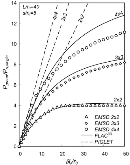
Fig. 2 shows comparisons of normalized global load– displacement solutions of the EMSD, finite difference, and PIG-LET for the different pile groups. The pile group displacement,␦, is normalized using the pile radius and the rigidity factor, Ir =G/su, whereas the pile group load, Pgroup, is normalized by the theoretical value of an individual pile capacity of
Pu,single= 2r0Lsu+r0 2N
csub 共11兲 where L= length of the pile and Nc= bearing capacity factor, is taken as 9 in the current calculations. Note that this value corre-sponds to the capacity based on alpha method 共i.e., total stress method; O’Neill 2001兲, with an ␣ value of 1.0. The suggested method may not be limited to this condition, as for smaller values of␣a relatively thin annular zone with an ultimate shear strength of␣sucan be introduced into the domain. The energy method will implicitly consider this annular zone as an interface.
[image:4.612.330.555.36.321.2]As can be seen from Fig. 2, all solutions agree well in the initial elastic stage. As the load increases the finite difference and EMSD exhibit nonlinearity, which causes the curves to diverge from the PIGLET “elastic” lines. Fair agreement is observed be-tween the finite difference and the EMSD solution for the 2⫻2 and 3⫻3 pile groups, with a difference less than 7%. For these cases the EMSD ultimate capacity corresponded to the sum of
Fig. 2.Comparison of EMSD to finite difference共FLAC3D兲and
individual pile capacities. The finite difference solutions overes-timate these values, possibly due to the following two reasons:共1兲 the Nc value used in the normalization is smaller than the value developed in the finite difference simulation and共2兲FLAC3Duses constant strain elements, and it can be shown using an energy calculation that the ultimate shaft resistance under load– displacement simulation will be overestimated by approximately 1 +, where= ratio between the thickness of the element nearest to the pile shaft and the pile diameter. In the current simulations was 0.045.
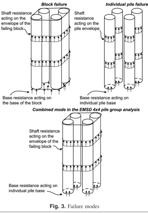
The underestimation of the 4⫻4 pile group stiffness by EMSD is attributed to different reasons. In the current EMSD formulation the shaft and base responses are decoupled. The EMSD method predicted a block-type failure mechanism for the 4⫻4 group when shaft resistance alone is considered. However, the base response model does not capture a block-type failure mode. On the other hand, theFLAC3Dsimulation considers both shaft and base responses holistically. The failure mode revealed by FLAC3D is somewhat between a block mechanism and an individual pile failure mechanism, resulting in a more significant discrepancy when compared to the EMSD predictions. Fig. 3 il-lustrates the different failure modes, and the EMSD mechanism for the EMSD 4⫻4 pile group.
The underestimation of capacity is an outcome of the decou-pling of base and shaft resistance models. Nonetheless, as the EMSD will choose the smaller capacity between block failure and individual pile failure mechanisms for the shaft response, the de-coupling process is always conservative in the current formula-tion, and hence the approach is safe for design purposes. As mentioned before, the current base response model is a crude approximation. It is quite possible that a better model, based on
the presented EMSD concepts, may resolve the issues posed by the decoupling process used in the current work.
The above-presented examples are associated with homog-enous soil. However, the formulation is not limited to that par-ticular scenario. For the special case where the soil stiffness and strength increase linearly with depth共asIrremains constant with depth兲, the EMSD solution for the shaft resistance may be ob-tained usingG andsuat middepth of the pile. In this case, rm
RW
=2.5L共1 −兲 according to Randolph and Wroth 共1979兲 elastic solution, where= ratio of the shear modulus at middepth to that at the pile base level.
Fig. 4 shows results for different linear variations of stiffness and strength for the 2⫻2 pile group. Results were normalized with the ultimate capacity from Eq.共11兲using soil shear strengths at middepth of the pile for shaft resistance and at pile base level for base resistance. The agreement between the finite difference and the EMSD is fair, but not as good as that for homogenous soil. One possible contribution to the apparent difference is that soil properties at pile base level were used to formulate the base resistance in the EMSD, whereas the increasing soil strength and stiffness below the pile base may result in increased capacity in theFLAC3Danalysis.
Summary and Conclusions
A method was presented for predicting the nonlinear behavior of pile groups in clays. The method is an extended version of the mobilizable strength design method in which the deformation field is allowed to change throughout the loading process in order to achieve minimum internal work. As an MSD method it enables up-scaling of stress–strain curves from shear tests to global load-displacement solutions, offering practitioners an attractive tool to relate site exploration data to the actual pile group response.
The method allows for consideration of a nonlinear
[image:5.612.46.288.34.381.2]con-Fig. 3.Failure modes
[image:5.612.332.555.37.310.2]tinuum, and is fundamentally different from other common ap-proaches, such as inclusion of slip elements, which limit contact stresses between the pile shaft and the soil, or nonlinear load transfer functions in which the continuum is not explicitly con-sidered. Nonetheless, under small strain levels, associated with linear elasticity, the method predicts values comparable with com-mon design programs, such as PIGLET共Randolph 2003a兲.
To evaluate the method, simulations of pile group loading in undrained conditions were conducted. Comparisons were made with three-dimensional finite difference analyses, for several pile group configurations and soil profiles. For homogenous soil, fair agreement共with differences less than 7%兲was observed between the methods as long as the failure mechanisms were the same. The current base resistance model cannot capture block-type fail-ure, and due to the decoupling of base and shaft resistance mod-els, the current EMSD method may develop a block-type failure in the shaft model, even when such mechanism is prevented in reality due to the associated large base resistance. Nonetheless, the values produced by the EMSD method are always conserva-tive under such conditions.
The current simulations, and comparison with other methods, were performed for loading in undrained conditions. Although the concentric cylinder mechanism may also be suitable for drained loading 关as the Randolph and Wroth 共1978兲 model is not re-stricted to a Poisson’s ratio of 0.5兴, such evaluation was not per-formed and further work is required to validate and evaluate the suitability of the method in other conditions.
In addition, the current method is limited to incompressible piles under a rigid cap. Although this condition might be suitable for concrete piles it may not be appropriate for long steel piles. Also, as a MSD method, it requires a stress–strain curve for the soil behavior. In many scenarios the soil behavior may be altered due to installation effects. In these cases, stress–strain curves can be obtained from samples extracted after the installation共of, say, a preliminary test pile兲. These stress–strain relationships, which reflect the installation effects, can be used to refine the analysis.
Although the method allows the practitioner to incorporate soil testing data into pile group design, in situ pile load testing is still considered to be the best way to verify engineering analyses and provide information on fine adjustments in the design of pile
groups. It is therefore suggested that the method be used with caution until such validation against field test is performed.
References
Basile, F.共1999兲. “Non-linear analysis of pile groups.”Proc., Inst. Civ. Eng., Geotech. Eng., 137共2兲, 105–115.
Bolton, M. D., and Powrie, W.共1988兲. “Behaviour of diaphragm walls in clay prior to collapse.”Geotechnique, 38共2兲, 167–189.
Itasca. 共2005兲. FLAC3D—Fast Lagrangian analysis of continua in 3
dimensions—User’s manual, Minneapolis.
Klar, A. and Osman, A. S.共2008兲. “Load-displacement solutions for piles and shallow foundations based on deformation fields and energy con-servation.”Geotechnique, 58共7兲, 581–589.
Klar, A., and Randolph, M. F. 共2008兲. “Upper-bound and load– displacement solutions for laterally loaded piles in clays based on energy minimization.”Geotechnique, 58共10兲, 815–820.
Lee, K. M., and Xiao, Z. R.共2001兲. “A simplified nonlinear approach for pile group settlement analysis in multilayered soils.”Can. Geotech. J.,
38共5兲, 1063–1080.
O’Neill, M. W. 共2001兲. “Side resistance in piles and drilled shafts.”J. Geotech. Geoenviron. Eng., 127共1兲, 3–16.
O’Neill, M. W., Hawkins, R. A., and Mahar, L. J.共1982兲. “Load transfer mechanisms in piles and pile groups.” J. Geotech. Engrg. Div.,
108共12兲, 1605–1623.
Osman, A. S., and Bolton, M. D.共2005兲. “Simple plasticity-based pre-diction of the undrained settlement of shallow circular foundations on clay.”Geotechnique, 55共6兲, 435–447.
Poulos, H. G.共1968兲. “Analysis of the settlement of pile groups.” Geo-technique, 18共4兲, 449–471.
Poulos, H. G. 共1989兲. “Pile behaviour—Theory and application.” Geo-technique, 39共3兲, 365–415.
Randolph, M. F.共2003a兲.PIGLET manual version 4.2: Analysis and de-sign of pile groups, Univ. of Western Australia, Australia.
Randolph, M. F.共2003b兲.RATZ manual version 4.2: Load transfer analy-sis of axially loaded piles, Univ. of Western Australia, Australia. Randolph, M. F., and Wroth, C. P. 共1978兲. “Analysis of deformation of
vertically loaded piles.”J. Geotech. Engrg. Div., 104共12兲, 1465–1488. Randolph, M. F., and Wroth, C. P.共1979兲. “An analysis of the vertical
deformation of pile groups.”Geotechnique, 29共4兲, 423–439. Storn, R., and Price, K. 共1997兲. “Differential evolution—A simple and