Aquifer rehabilitation project
Inbal David, Arina Shulman, Anna Lordian, Amos Duer, Menahem Priel
Mekorot Water Co., Desalination and Special Projects Division, Tel-Aviv, Israel
Abstract
The Coastal Aquifer is one of Israel’s main groundwater sources. Tens of years of intensive pumping from the aquifer as well as irrigation with treated effluents resulted in continuous increases in salinity of the aquifer. The objective of the rehabilitation project is to prevent salt penetration to the coastal aquifer from the eastern side. This can be achieved by creating a "buffer zone" by pumping brackish water from a row of 35 wells, at a capacity of about 40 Mm3/day .
Since 2011, as part of the Aquifer Rehabilitation project, two new desalination plants were established to treat this brackish water: (1) Granot Expansion – a second desalination unit in the existing Granot desalination site; (2) Lahat – two desalination units were built at this new site. As a result, the desalinated water capacity from the eastern part of the aquifer increased from 13,000 m3 a day to 43,000 m3 a day, or 14.3 Mm3 a year. In the final step of the project, the Granot and Lahat capacities will sum up to 99,000 m3 a day, or 33 Mm3 a year, by establishing five additional desalination units, three in Granot and two in Lahat.
Brine disposal was one of the major issues to be resolved when executing this project. Mekorot constructed a long underground pipeline of about 30 km, from the inland plants to the Mediterranean Sea, through the Ashkelon power station's outfall.
The disposed brine capacity through the brine pipeline has increased from about 3,000 m3 a day in 2004, to about 10,000 m3 a day in 2011. The quantity of the disposed chloride from the aquifer has increased from about 3,000 to 11,000 tons of chloride per year. In both sites, Granot and Lahat, pilot plants were founded. Both pilot plants contain a desalination branch, for simulating the commercial plant. The Granot pilot plant also contains a brine recirculation system for simulating the brine flow in the long brine pipeline. The two systems, the desalination branch and the brine recirculation, enable testing different parameters from two aspects: (i) the effect on the RO membranes' performance and (ii) the effect on the possibility of salt precipitation in the brine pipeline.
One of the main field tests conducted at the pilot plant is testing phosphorus free antiscalants. This test is required by the Israeli Ministry of the Environmental Protection .
The operation and maintenance of a 30 km brine pipeline is a unique challenge including chemical and hydraulic control. In the future, this pipeline could also serve private desalination plants in the region .
The whole project is designed and executed by Mekorot with the full cooperation of the Israeli Water Authority. The general hydrological design of the project was carried out by Tahal.
1. Introduction
Since the turn of the century, the Israeli Water Authority decided to establish brackish water desalination plants in order to rehabilitate the coastal aquifer by removing the salt that has been penetrating the aquifer. This is due to the fact that along the years the water quality of the coastal aquifer has deteriorated as a result of over pumping as well as contamination intrusion from agricultural activities, industries, and other anthropogenic activities. The over exploitation lead to a decrease in groundwater level which resulted in the intrusion of seawater from the west as well as brackish water penetration from the east [5].
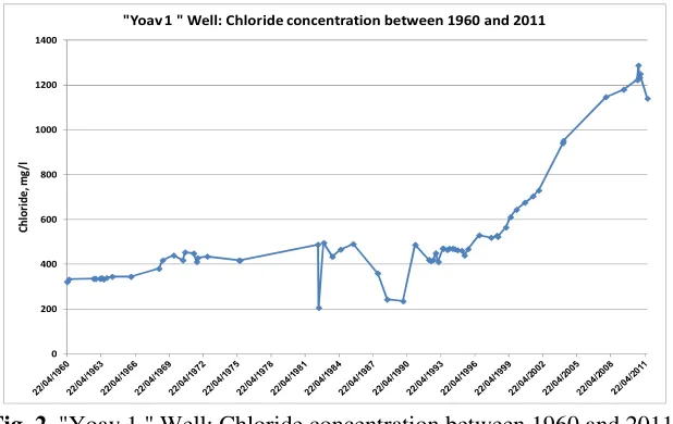
The changing rate of chloride concentration at wells located at the southern coastal aquifer, adjacent the eastern border of the aquifer, can illustrate the deterioration of the groundwater quality. At "Shafir 1" well, the chloride concentration increased from 230 mg/l during the 1960's to 630 mg/l during the last years (Figure 1) [1]. At "Yoav 1" well, the situation is even worse: the chloride concentration increased from 320 mg/l during the 1960's to 1200 mg/l during the last years (Figure 2).
[image:2.595.144.453.280.463.2]Fig. 1: "Shafir 1 " Well: Chloride concentration between 1960 and 2011.
Fig. 2. "Yoav 1 " Well: Chloride concentration between 1960 and 2011.
In order to rehabilitate the aquifer, two desalination plants were built (between Ashkelon and Kiryat Malachi) in 2004 – Granot and Gat. Since these are inland facilities a brine disposal pipeline had to be constructed to transport the brine from the plants to the Mediterranean Sea.
0 100 200 300 400 500 600 700 800
C
h
lo
ri
d
e
, m
g
/l
"Shafir 1 " Well: Chloride concentration between 1960 and 2011
0 200 400 600 800 1000 1200 1400
C
h
lo
ri
d
e
, m
g
/l
[image:2.595.144.453.495.690.2]Over the following years, Mekorot and the Israeli Water Authority introduced the "Eastern Buffer Zone Project" whose long-term objectives were to stop the groundwater salination process and to rehabilitate and preserve the aquifer, as part of Israel’s national water source. As part of the project, a row of wells is being drilled along the eastern side of the aquifer. In addition, two brackish water desalination plants were constructed near Granot: Granot "Expansion" and Lahat. This row of wells consists of 40 consecutive wells that will have the capacity of 35-40 million m3 per year. [5].
2. The desalination plants for aquifer rehabilitation
2.1Capacities
The aquifer rehabilitation project includes an expansion of the existing desalination plant at Granot and establishment of new desalination plant: Lahat, near "Talmei-Yaffe". A schematic map for the location of the desalination plants, the row of wells and the brine disposal pipeline is shown in Figure 3.
Fig. 3. A Schematic map of the row wells, the desalination plants and the brine pipeline locations – Coastal Aquifer Rehabilitation project.
The Granot BWRO (Brackish Water Reverse Osmosis) plant is being expanded from 9,000 m3 a day up to 41,600 m3 a day at the end of 2012. On the final expansion step, the total capacity of the Granot plant will be about 54,000 m3 a day. The first expansion step was successfully completed on the last February (2011): the second RO unit of 10,000 m3 a day, at the Granot plant started operating. Hence, the capacity of Granot desalination plant reaches today to 19,000 m3 a day.
[image:3.595.109.476.309.576.2]Figure 8 presents photos from both plants. The final designed capacity of the Granot and Lahat BWRO plants is about 33 million m3 a year. The required feed water capacity at the final step will be about 40 million m3 a year, most of it will originate from the Eastern Buffer Zone project row of wells.
2.2Process
The pretreatment: The pretreatment at the Granot and Lahat plants includes only cartridge
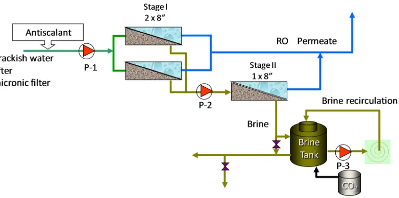
filters. This design was a result of comprehensive engineering work that creates an economic saving in energy consumption and in chemical consumption. A simplified flow diagram of a single RO unit is presented in Figure 4.
Fig. 4. The Granot BWRO plant: A simplified flow diagram of a single RO unit.
The desalination unit: The desalination unit contains two RO stages with inter stage booster
pump. Two major components of the raw water in these wells influence the desalination process: boron and silica. The expected boron content in the raw water from the Eastern Buffer Zone wells is between 0.5 and 0.8 mg/l. The silica level in the raw water will range from 26 to 30 mg/l. These components mainly affect three parameters: the selection of the RO membrane type, the RO recovery ratio and the chemical regime (i.e. the antiscalant type and dosage as well as the acid usage).
The RO membrane type that was selected for the new units is seawater membrane (SWRO), produced by different manufacturers. The high boron rejection of the seawater membranes enables achieving the required boron concentration level of the product water, 0.35-0.40 mg/l, as determined by the Israeli Water Authority. The SWRO membranes would be suitable in case of an increase in the boron level of the well water (as predicted by the hydrological forecast).
[image:4.595.123.483.238.465.2]Experiments with special antiscalants for preventing silica scaling will be conducted with various recovery ratios, at the Granot pilot plant.
When the RO recovery ratio and the chemical regime are determined, they also have to correspond to the requirements of the long brine disposal pipeline, in order to prevent precipitation in the pipeline [3,4].
The high chloride rejection of the seawater membranes assures achieving the required chloride concentration level of the product water: 20-50 mg/l. The chloride concentration in the raw water today ranges between 570 and 750 mg/l. During the gradual addition of raw water from the other Eastern Buffer Zone wells, the concentration range will be around 700-750 mg/l. According to the hydrological forecast the chloride concentration at the Eastern Buffer Zone wells is expected to increase by up to 900 mg/l in the next ten years.
The post treatment: The desalinated product water of the two plants is stabilized for meeting
the water quality regulations. In this current step, the stabilization is carried out by blending the product water with well water. In the next step, the water remineralization will be performed by the dissolution of limestone filters.
In order to optimally design the remineralization system, a technical-economic model has been developed. The model was based on laboratory test results attained at the Technion Institute, by Prof. Hasson’s and Prof. Semiat’s team. Remineralization plants are currently being designed and constructed in Granot and Lahat.
3. The brine disposal pipeline
Mekorot constructed1 a long underground pipeline of about 30 km, from the inland plants (Granot, Gat and Lahat) to the Mediterranean Sea, through the Ashkelon power station's outfall. Since 2004 Mekorot brine disposal pipeline (the Granot-Ashkelon brine pipeline) has been collected the brine from the Granot and Gat desalination plants. Since 2011, the brine from the Lahat plant is also collected to the pipeline. The pipeline was designed for maximal flow of 1000 m3/h. The actual brine flow in the pipeline increased from 130 m3/h to 441 m3/h, since the operation of the new plants, Lahat and Granot 2 (Granot Expantion).
A new hydraulic examination of the brine pipeline has to be performed to check how it operates at the maximal flow rate that the line was designed for. This is due to the increase in brine flow from the desalination plants. In addition, Mekorot has to consider several requests from private users to discharge brine from their desalination plants to the Mekorot Granot – Ashkelon brine disposal line.
Mekorot invests efforts in control and management of the brine disposal pipeline, in order to prevent scale precipitation along the pipe [4].
4. Research at the Granot pilot plant
Mekorot has several RO pilot plants at the commercial RO plant sites. The major objectives of these pilot plants, which operate parallel to the commercial plants, are optimizing the process and testing new chemicals, new membranes and new technologies in order to achieve the best operation, producing the highest water quality, in the most economical way [2]. The Granot pilot plant was established for an additional purpose: testing the possibility of replacing the common usage of polyphosphonate antiscalants with phosphorous free antiscalants. The need for this test was brought up by the Ministry of Environmental Protection as part of their yearly approval for seawater brine disposal.
The disposed brine from the RO plants contains high concentration of antiscalant, which was injected into the RO feed water, to prevent scaling on the RO membranes. Thus an environmentally friendly antiscalant should be implemented in these desalination plants, in order to protect the seawater that receives the disposed brine.
A comprehensive test that confirms the use of a specific antiscalant in the plants that have a long brine disposal line should include two parts. The first is testing the RO membranes’ performance while using the tested antiscalant. The second is testing the behavior of the disposed brine which contains the tested antiscalant, along the brine disposal line (i.e. checking that no precipitation occurs).
In 2005 Mekorot carried out the first step for testing phosphorus free antiscalants by performing a field experiment at the Sabha BWRO pilot plant, in the Eilat site. This experiment tested the phosphorus free antiscalant type B. In the second step, a series of laboratory tests was performed in 2006-2007 by Prof. R. Semiat at the Technion Institute, using a special system for testing the RO performance and a brine recirculation system. In 2009 the Granot pilot plant was commissioned for field investigation. The pilot consists of two systems. The first is the RO unit, which contains two desalination stages using 8 inch commercial RO membranes to test the RO performance. The second is the brine recirculation system that simulates the brine flow along a 30 km pipeline.
The flow diagram of the pilot plant is shown in Figure 5.
[image:6.595.84.475.528.722.2]4.1.Results from the pilot plant and discussion 4.4.1 The RO system
Three types of antiscalants have already been tested at the pilot plant: the first contains phosphorous (type X2), while the second (type A) and third (type B) – do not contain phosphorous.
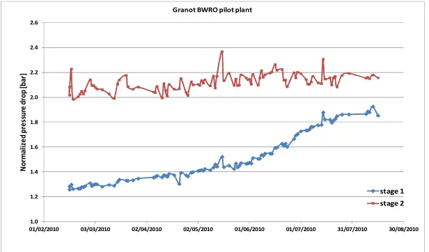
Antiscalant A was tested between February and August of 2010, with an RO recovery ratio of 80%. Throughout this period the pressure drop on the first RO stage had gradually increased, from 1.30 bar to 1.86 bar, an increase of 43% in about 160 days. The pressure drop on the second RO stage was quite stable.
Figure 6 shows the membrane performance, in terms of the normalized pressure drop, while operating with antiscalnt type A.
On the other hand, the increase in pressure drop in the Granot commercial RO plant that operated parallel to the pilot plant was significantly lower. This is in spite of the fact that both plants had the same RO recovery ratio (80%), they were fed by the same feed water, after the same pretreatment. However, in the commercial plant a phosphorous antiscalant was used.
Fig. 6. Normalized RO pressure drop with phosphorous free antiscalant type A.
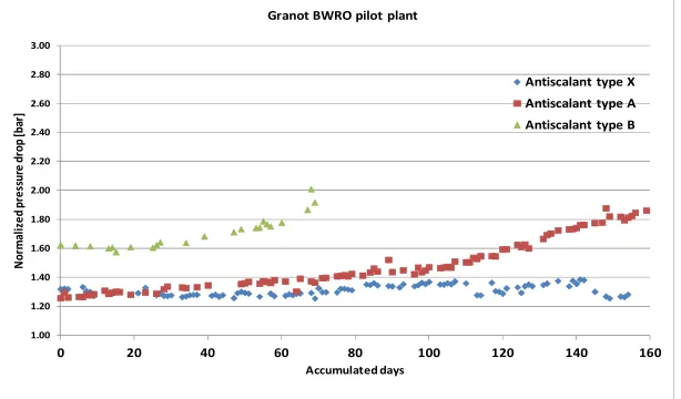
While using antiscalant B (non phosphorous) the pressure drop in the first RO stage was increased from 1.63 bar to 1.91 bar, an increase of 17% in about 70 days.
However, while using the phosphorous antiscalant, type x, a very stable performance was shown. The pressure drop ranged between 1.25 bar to 1.38 bar, an approximate 10% increase in about 160 days.
Figure 7 shows the comparison between the membrane performances, in terms of a normalized pressure drop, while operating with the three types of antiscalants.
Following the above presented results, two of the three antiscalants were tested at higher RO recovery ratio of 83%: antiscalant A and X. With both antiscalants the membranes’ performances were similar to the performances that showed at 80% recovery.
According to these data and the testing conditions at the Granot site, it seems that the best RO performance was achieved with the phosphorous antiscalant (type x). The worse performance was shown while using the non-phosphorous antiscalant type B.
2 1.0 1.2 1.4 1.6 1.8 2.0 2.2 2.4 2.6
01/02/2010 03/03/2010 02/04/2010 02/05/2010 01/06/2010 01/07/2010 31/07/2010 30/08/2010
N o rm al iz e d p re ss u re d ro p [b ar ]
Granot BWRO pilot plant
stage 1
[image:7.595.145.453.317.498.2]The stable performance of the second RO stage (shown in Figure 6) indicates that salt scaling did not occur. The increase in pressure drop that occurred in the first stage only, indicates the possibility of fouling from the feed. It leads to the assumption that phosphorous free antiscalant may enhance biofouling growth.
The fact that the increase in recovery didn't deteriorate the membranes’ performance when antiscalant A (non-phosphorous) was added, reinforces the assumption above. The relatively high increasing rate of the pressure drop while using a non-phosphorous antiscalnt derived from organic fouling that didn't appear while using a phosphorous antiscalant.
Fig. 7. Normalized RO pressure drop with three types of antiscalants.
The fact that the increase in recovery didn't deteriorate the membranes’ performance when antiscalant A (non-phosphorous) was added, reinforces the assumption above. The relatively high increasing rate of the pressure drop while using a non-phosphorous antiscalnt derived from organic fouling that didn't appear while using a phosphorous antiscalant.
4.4.2 Tests at the Sabha BWRO plant
Experiments testing phosphorous free antiscalants have been carried out since 2007 at a commercial RO unit of the Sabha BWRO plant, in Eilat. Numerous experiments were performed using antiscalant type B, over a period of 9 months. Other experiments were executed using antiscalant type A over a period of 7 months.
For the antiscalant B tests: the normalized pressure drop on the RO membranes increased by 45% and 50% throughout a period of 3.5 and 3 months, respectively.
For the antiscalant A tests: the normalized pressure drop on the RO membranes increased by 75% during a period of 4 months. Throughout these long periods of experiments, a "regular" antiscalant (with phosphorous) was used between the tests. The normalized pressure drop was stable during these periods. An additional comparison can be made with the RO membrane performance of other commercial RO units in the Sabha BWRO plant. During these experiments, the other units operated with a "regular" antiscalant (with phosphorous) using the same feed water as the tested unit. Their performances were stable, especially in terms of pressure drop (two examples: an increase in RO pressure drop of 9% and 17% over a 6 month period and a 7 month period, respectively).The conclusion from the Sabha experiments was that the two phosphorous free types of antiscalants that were tested, both A and B types,
1.00 1.20 1.40 1.60 1.80 2.00 2.20 2.40 2.60 2.80 3.00
0 20 40 60 80 100 120 140 160
N o rm al iz e d p re ss u re d ro p [b ar ] Accumulated days Granot BWRO pilot plant
Antiscalant type X
Antiscalant type A
[image:8.595.146.453.198.378.2]caused a rapid increase in membrane pressure drop as well as a deterioration of membrane performance.
4.4.3 The brine recirculation system for simulating the brine flow
The different types of brine, that contained different types of antiscalants or were produced at a different recovery ratios, were circulated in the brine recirculation system. During the recirculation of the brine water with each one of the antiscalants that have been tested in the RO system, at 80% and 83% of recovery, precipitation didn't occur. Each recirculation test had been performed for at least 120 hours.
5. Summary
During 2007 and 2009, the annual chloride removal from the groundwater, by operating Israel’s Gat and Granot desalination plants, was about 3,000 tons of chloride [4]. Today, by operating Gat, Granot and Lahat (the first step), the annual chloride removal is expected to increase to 10,000 - 13,000 tons of chlorides per year.
The desalination of about 40 million m3 of brackish water a year, as part of the Coastal Aquifer Rehabilitation project, will remove about 26,000 tons of chloride from the aquifer every year. It seems that within the next years, the national goal to rehabilitate the aquifer will be close to achievement.
Optimizing the operation of the desalination plants has to be further investigated, and the brine disposal pipeline management must be additionally developed, in order to maximize efficiency and continue saving our environment.
(b) Lahat RO hall (a) Granot RO hall (after 1st expansion step)
[image:9.595.114.530.402.714.2]
(d) Lahat BWRO plant, general view (c) Granot BWRO plant, general view
References
[1]E. Kotzer, Artificial kidneys for the soil – solving the problem of salinization of the soil and underground water, Desalination 185 (2005) 71.
[2]P. Glueckstern, A. Thoma, M Priel, The impact of R&D on new technologies, novel design concepts and advanced operating procedures on the cost of water desalination, Desalination 139 (2001) 217
[3]R.Semiat, D. Hasson, G. Zelmanov and I. Hemo, Threshold scaling limits of RO concentrates flowing in a long waste disposal pipeline, Water Science and Technology, 49(2) (2004) 211. [4]A. Shulman, I. David, E. Gelman and M. Priel , Control and management of brine disposal for
inland desalination plants, Desalination, 31 (2011) 71.
] 5 [ יחרזמה זקנה יחודיק טקיורפ ,בגנ .ע –
םימ ,ףוחה תווקא םוקישו החלמהה ךלהת תמילבל תינכותב ןושאר בלש
הייקשהו 512