Upper stage plane bed in the Netherlands
69
0
0
Full text
(2)
(3) Upper Stage Plane Bed in the Netherlands. December 2016. Submitted to acquire the degree of Master of Science To be presented in public on 22 December 15.45h, OH116, de Horst At the University of Twente, Enschede, the Netherlands. Roy Johannes Daggenvoorde S1095595 [email protected]. University of Twente Faculty of Construction Engineering Technology Water Engineering and Management. Members of the graduation committee: prof. dr. S.J.M.H. Hulscher. Chairman, University of Twente. dr. J.J. Warmink. Supervisor, University of Twente. ir. drs. K. Vermeer. Supervisor, HKV Consultants. HKV. CONSULTANTS. i.
(4) Upper Stage Plane Bed in the Netherlands. December 2016. Preface This report is the result of my master thesis for the study Water Engineering and Management at the University of Twente. It will mark the end of a personal era, my life as a student. It will also mark the start of a new one, the working life of a civilian. The last six and a half years I spent at the University of Twente and I can look back to a wonderful period over there. I made lots of friends and met wonderful people. I would like to thank them all for making this period in my life as awesome as it was. Luckily these friendships don’t end and we will continue to have lots of fun with all of us. The report in front of you could not have been there without the help of lots of people. First of all I would like to thank Kees Vermeer for offering me the opportunity to do the research for my master thesis at HKV consultants. Every time I was a little stuck I could walk by your office and you had some ideas to continue with and along with those ideas you always told a story of how you encountered a similar problem yourself. I just want to say once more that I really enjoyed those stories and appreciated your help. I also would like to thank Jord Warmink and Suzanne Hulscher for their supervision and critical feedback that greatly helped to improve this report. To make sure I don’t forget anyone to thank I want to thank you, the reader right now! I hope you enjoy reading my thesis!. Roy Daggenvoorde. Lelystad, December 2016. ii. HKV. CONSULTANTS.
(5) Upper Stage Plane Bed in the Netherlands. December 2016. Summary The Netherlands is vulnerable to flooding, both from the rivers and the sea. To counter these threats the Dutch protect themselves with dikes and other flood protection measures. These protective measures are designed to withstand a design water level. To be able to predict the design water levels the processes determining the water levels need to be understood. Amongst others bed roughness is an important factor determining the water depth. So it is important to know the form of the river bed. Upper Stage Plane Bed (USPB) is a river bed form. When USPB is present at the bottom of a river, the river bed is less rough compared to dunes and ripples. The presence of USPB in a river in the Netherlands during design discharge is expected to reduce the design water levels up to 0.5 meter. Whether USPB in the Netherlands develops under design conditions is still unknown and is the focus of this study. The study comprehends two mayor parts. The first part focusses on finding the location with the most USPB favourable conditions and the second part uses a dune evolution model in order to predict dune evolution under design discharge. The USPB-index has been formulated to find the most probable location for USPB in the Netherlands. This index is based upon the Froude and Suspension numbers along with a threshold which is based upon observations of dunes and plane beds. The index allows comparing different locations to each other on their probability to develop USPB. The lower the USPB-index the more likely the location is to develop USPB and when the index drops below zero, USPB is expected to develop. This index indicated the IJssel near Kampen as the most probable location for USPB to develop in the Netherlands, with the river Lek near Tienhoven-Lopik as the second location. The second part of this study applied the model of Van Duin (2015) on the IJssel near Kampen and the Lek near Tienhoven-Lopik. By performing three calibrations the model could be applied on river scale. The morphological module of the model has been calibrated upon equilibrium dune heights in flume experiments (Coleman et al., 2005; Naqshband et al., 2014c), the calibration led to a Nash-Sutcliffe-coefficient (NS-value) of 0.69. Secondly the hydrodynamic module was calibrated on a river scale, aiming to reproduce the observed dune heights in the Waal in 20022003 (Sieben, 2004), resulting in an NS-value of 0.3. The morphological module did not need to be calibrated again since it is standardized for different water depths (applicable on flume and river scale). The third calibration aimed to correctly reproduce the moment when the bed form in a simulation changes from dunes to a plane bed. This has been done by changing the step-lengthmodel such that the conditions when USPB is present have an UPSB-index below zero. This steplength-model is within the morphological module of the model and could be changed without influencing the resulting dune heights. The fully calibrated model showed that the IJssel near Kampen did develop USPB. In the river Lek near Tienhoven-Lopik dunes remained present during the design discharge wave. So, within the Netherlands, USPB is only expected to occur in the river IJssel near Kampen. Due to the lack of data on the transition to USPB in both flumes and rivers this transition to USPB is calibrated upon observations of dunes and plane beds, instead of the transition itself. To cover this and other uncertainties further research is needed. The transition to USPB needs to be validated by field observations or flume experiments and the calibrated model needs to be validated for other rivers than the Waal. These follow-up-studies can lead to enough knowledge to be able to use the beneficial water level reducing effect of this plane bed when designing flood protection measures.. HKV. CONSULTANTS. iii.
(6) Upper Stage Plane Bed in the Netherlands. December 2016. Contents List of Tables ..................................................................................................vi List of Figures ................................................................................................ vii Nomenclature ............................................................................................... viii 1. 2. Introduction ............................................................................................. 1 1.1. Context .......................................................................................................................... 1. 1.2. Previous research on USPB ............................................................................................... 2. 1.3. Research gap .................................................................................................................. 4. 1.4. Research objective & questions ......................................................................................... 4. 1.5. Thesis outline ................................................................................................................. 5. Most probable locations for USPB ............................................................. 7 2.1. 2.2. 2.3. 3. Indicators for Upper Stage Plane Bed ................................................................................. 7 2.1.1. Data acquisition .................................................................................................. 7. 2.1.2. Data processing .................................................................................................. 8. USPB-index along the Dutch river system ........................................................................... 8 2.2.1. Current design conditions..................................................................................... 8. 2.2.2. Increased design conditions ............................................................................... 11. Synthesis on the most probable locations for USPB ............................................................ 11. Modelling dune development of flume experiments – Driving factors for USPB ................................................................................................. 12 3.1. Dune evolution model choice .......................................................................................... 12 3.1.1. 3.2. 3.3. Model sensitivity & calibration ......................................................................................... 15 3.2.1. Sensitivity of dune height................................................................................... 16. 3.2.2. Calibration ....................................................................................................... 18. Driving factors for USPB ................................................................................................. 19 3.3.1. 3.4. 4. Scaling up to river scale ................................................................................................. 22 4.1.1. 4.2. Dune height data Sieben (2004) ......................................................................... 22. Calibration & validation of dune height simulation on river scale .......................................... 22 4.2.1. Calibration of dune height on river scale .............................................................. 23. 4.2.2. Validation on river scale ..................................................................................... 24. 4.3. Calibration of the transition to USPB ................................................................................ 25. 4.4. Synthesis on the model application on river scale .............................................................. 27. USPB development in Dutch rivers ......................................................... 29 5.1. 5.2. iv. USPB development under various conditions ........................................................ 19. Synthesis on the model and USPB in flume conditions ........................................................ 21. Modelling dune development on river scale – Transition to USPB ........... 22 4.1. 5. Model description .............................................................................................. 12. USPB development in the Dutch river system.................................................................... 29 5.1.1. Dune development near Kampen ........................................................................ 29. 5.1.2. Dune development near Tienhoven-Lopik ............................................................. 30. Synthesis on USPB-development in Dutch rivers ............................................................... 31. HKV. CONSULTANTS.
(7) Upper Stage Plane Bed in the Netherlands. December 2016. 6. Discussion .............................................................................................. 32. 7. Conclusions & Recommendations ........................................................... 35. 8. 7.1. Conclusions .................................................................................................................. 35. 7.2. Recommendations ......................................................................................................... 36. References .............................................................................................. 39. Appendix A: Variables along the river branches ........................................... 44 Appendix B: Dune evolution models & model choice ..................................... 48 Appendix C: Sensitivity of the equilibrium dune height ................................ 52 Appendix D: Flume experiments used for calibration .................................... 53 Appendix E: Dune height evolution ............................................................... 54 Appendix F: USPB-transition for different grain sizes ................................... 58. HKV. CONSULTANTS. v.
(8) Upper Stage Plane Bed in the Netherlands. December 2016. List of Tables Table 1 List of Symbols ................................................................................................................... viii Table 2 Constants required for Froude & Suspension numbers ................................................................ 7 Table 3 Sediment transport model parameters ................................................................................... 15 Table 4 Base case sensitivity analysis................................................................................................ 16 Table 5 Updated step-length-model .................................................................................................. 18 Table 6 Variables at the calibration and validation locations ................................................................. 23 Table 7 Simulations periods ............................................................................................................. 23 Table 8 Updated step-length-model for D50 = 0.25 mm ...................................................................... 27 Table 9 Results of the calibration and validation with the updated step-length-model .............................. 27 Table 10 Comparison of dune evolution models *these computational time scores are based upon preliminary tests with the models. ............................................................................... 51 Table 11 Pros and cons for the models of Shimizu et al. (2009) and Van Duin (2015) ............................. 51 Table 12 Characteristics of the flume experiments used for the first calibration, the first fifteen experiments are from Coleman et al. (2005) and the last two from Naqshband et al. (2014c) .................................................................................................................... 53. vi. HKV. CONSULTANTS.
(9) Upper Stage Plane Bed in the Netherlands. December 2016. List of Figures Figure 1 Flood risk chart of the Netherlands, in red the area vulnerable to flooding (InterprovinciaalOverleg, 2014) ............................................................................................................ 1 Figure 2 River bed forms and corresponding roughness under increasing flow velocity (Knighton, 1998) ......................................................................................................................... 2 Figure 3 USPB-prediction graph based upon Suspension and Froude numbers (Naqshband et al., 2014b) ....................................................................................................................... 3 Figure 4 USPB-likeliness of the Dutch rivers ......................................................................................... 9 Figure 5 The Lake-dominated, Discharge-dominated and the transition region (Meergebied, Overgangsgebied and Afvoergeboied respectively) in the IJsseldelta (Kroekenstoel, 2014) ....................................................................................................................... 10 Figure 6 USPB-index map ................................................................................................................ 10 Figure 7 USPB-likeliness in the Waal with a discharge of 18000 m3/s at Lobith ....................................... 11 Figure 8 Schematized model (Van Duin, 2015) ................................................................................... 13 Figure 9 Sensitivity of the dune height on model inputs ....................................................................... 16 Figure 10 Step-length-model-principle (Van Duin, 2015) – red line represents model used in this study ........................................................................................................................ 17 Figure 11 Results calibration morphological model (the codes represent the various experiments, see Appendix D) .............................................................................................................. 18 Figure 12 Discharge waves used to analyse USPB ............................................................................... 19 Figure 13 Dune field and dune height over time .................................................................................. 19 Figure 14 USPB-development under various conditions ........................................................................ 20 Figure 15 Calibration results for the observed dune heights, Beneden-Leeuwen 2002 .............................. 23 Figure 16 Validation results for the observed dune height, Beneden-Leeuwen 2003 ................................ 24 Figure 17 Validation results for the observed dune height, Varik 2002 ................................................... 24 Figure 18 Dune development at Varik, 2002 (simulations A & D are stopped earlier to save computational time) ................................................................................................... 25 Figure 19 The principle of 'shifting' the step-length-model ................................................................... 26 Figure 20 The effect of 'shifting' the step-length-model ....................................................................... 26 Figure 21 The calibration of the transition to USPB for the IJssel near Kampen ....................................... 26 Figure 22 Dune evolution with the updated step-length-model near Varik in 2002 .................................. 27 Figure 23 The conditions during the start of the plane bed period near Kampen ...................................... 29 Figure 24 Bed evolution near Kampen under design discharge .............................................................. 29 Figure 25 The calibration of the transition to USPB for the Lek near Tienhoven-Lopik .............................. 31 Figure 26 Dune evolution under design discharge at the Lek ................................................................ 31 Figure 27 Fluctuation of variables along the IJssel............................................................................... 44 Figure 28 Fluctuation of variables along the Pannerdensch Kanaal, Nederrijn & Lek ................................. 45 Figure 29 Fluctuation of variables along the Bovenrijn & Waal .............................................................. 46 Figure 30 Fluctuation of variables along the Maas ............................................................................... 47 Figure 31 Sensitivity of the equilibrium dune height on various parameters under constant discharge ....... 52 Figure 32 Dune height evolution near Beneden-Leeuwen with the initial step-length-model in 2002 .......... 54 Figure 33 Dune height evolution near Beneden-Leeuwen with the updated step-length-model in 2002 ...... 55 Figure 34 Dune height evolution near Beneden-Leeuwen with the initial step-length-model in 2003 .......... 56 Figure 35 Dune height evolution near Beneden-Leeuwen with the updated step-length-model in 2003 ...... 57 Figure 36 Effects of shifting the step-length-model with a grain size of 0.40 mm mm .............................. 58 Figure 37 Results of shifting the step-length-model with a grain size of 0.40 mm ................................... 58 Figure 38 Effects of shifting the step-length-model with a grain size of 0.60 mm .................................... 59 Figure 39 Results of shifting the step-length-model with a grain size of 0.60 mm ................................... 59. HKV. CONSULTANTS. vii.
(10) Upper Stage Plane Bed in the Netherlands. December 2016. Nomenclature Symbol. ̅. Physical quantity. Unit. Eddy viscosity. m2/s. River width. m. Chézy-coefficient. m1/2/s. Median grain size. mm. Model constant determining pick-up-rate. -. Froude number. -. Predicted values. -. Probability of a particle settling at distance x-s. -. Gravitational acceleration. m/s2. water depth. m. Reference water depth. m. Bed slope. -. Nash-Sutcliffe-Coefficient. -. Sediment deposition rate. s-1. Sediment pick up rate. s-1. Unit discharge. m2/s. Sediment transport. m2/s. Distance from the pick-up point ‘x’. -. Resistance parameter. m/s. Flow velocity in the horizontal direction. m/s. Shear velocity. m/s. Suspension number. -. Kinematic viscosity. m2/s. Flow velocity in the vertical direction. m/s. Fall velocity. m/s. Horizontal & Vertical model directions. m. Average value of the observations. -. Observed values. -. Bed level. m. Dimensionless step length. -. Dimensionless step lengths corresponding to. -. Turbulence model calibration constants. -. Relative density. -. Porosity. -. Free surface elevation. m. Shields parameter. -. Dimensionless grain shear strength. -. Dimensionless grain shear strength determining. -. Critical Shields parameter. -. von Karman-constant. -. Mean step length of a particle. m. Density of water. kg/m3. bed shear stress. N/m2. Table 1 List of Symbols. viii. HKV. CONSULTANTS.
(11) Upper Stage Plane Bed in the Netherlands. 1. Introduction. 1.1. Context. December 2016. The Netherlands is famous for its battle against water throughout history. It is vulnerable to flooding by sea and rivers, since a large part of the country is located below sea level or along mayor rivers (Figure 1). This battle against water has been going on for centuries (van der Brugge et al., 2006). The last decades a technocratic-scientific approach has been dominant (van der Brugge et al., 2006; van der Ham, 1999). Predicting river discharges and corresponding water levels is an important topic within this field of work. Dikes, levees and other protective structures are built to protect the Netherlands against flooding (van der Brugge et al., 2006). The dimensions and levels of these structures rely upon the predictions based upon design water levels, Figure 1 Flood risk chart of the Netherlands, which result from a normative discharge, in red the area vulnerable to flooding set by the government. (Interprovinciaal-Overleg, 2014). Along with the protection against flooding the Netherlands also uses its waterways for navigation. The port of Rotterdam and the Dutch waterways are an important connection for the German Ruhr Region. This means that maintaining minimum water levels for navigation is important as well, along with the protection against flooding. A lot of research has been done in order to predict and manage the water levels within the rivers. Relations between discharges and water levels are known for rivers in the Netherlands. These relations are updated when new measurements are available for calibration. However, not all processes are included within the predictive methods, because they are not entirely understood. One of those principles, and the main focus of this research, is Upper Stage Plane Bed (USPB). USPB is a river bed form wherein the entire bottom of the river has become flat (Figure 2, (Knighton, 1998)). This flattening of the bottom causes the form roughness to reduce and hence the resistance is lower, which allows water to flow faster. Faster flowing water results in lower water levels when discharge and river width remain constant. If USPB would occur within the Netherlands under design discharge conditions, it could mean that the corresponding design water level will be lower at that location while causing problems at other locations. This means that dikes and levees can be constructed at a lower level at some locations, while reinforcement could be necessary somewhere else. A report of Rijkswaterstaat (Adriaanse, 1986) describes discharge and water level measurements which suggest the presence of a plane river bed in the Bergsche Maas near Heusden. While this indication of USPB in Dutch rivers was already observed 30 years ago, there is still no evidence whether USPB occurred or not. In other countries USPB has been observed in mayor rivers. In the Missouri River (USA) USPB was observed between March and November 1967 (Delft-Hydraulics, 1986).. HKV. CONSULTANTS. 1.
(12) Upper Stage Plane Bed in the Netherlands. December 2016. Figure 2 River bed forms and corresponding roughness under increasing flow velocity (Knighton, 1998). 1.2. Previous research on USPB. Various studies have investigated river bed forms and USPB. This prior research on river bed forms led to several stability diagrams, which mostly use the Shields parameter and the sediment transport capability of the flow as bed-form-predictors. These stability diagrams also showed the possibility of USPB, which was always found in the region with higher sediment transport capability and a low critical Shields parameter (Simons & Richardson, 1966; Southard & Boguchwal, 1990; Van den Berg & Van Gelder, 1993; Van Rijn, 1984c). This higher transport capability is related to higher flow intensity. The leading expectation is that the occurrence of USPB is caused by higher flow intensities and the corresponding increase in suspended sediment concentration (Best, 2005; Fredsøe, 1981). This increase in suspended sediment concentration can be caused by either higher flow velocities or finer sediment. The influence of finer sediment corresponds with the previously mentioned stability diagrams, since finer sediment means lower required value for the Shields parameter. Naqshband et al. (2014c) studied the influence of suspended sediment on bed forms, especially on the development of dunes towards USPB. They claim that the occurrence of USPB can be predicted by two parameters; the Froude-number and the Suspension number. The prior is a parameter describing the relation between flow velocity and water depth (equation 1), the latter is a parameter presenting the ratio between bed shear velocity (u*) and the particle fall velocity (ws), also see equation 2. (1). ⁄√. (2). When the combination of these two values is situated above the threshold (dashed line in Figure 3) USPB is observed. The values in Figure 3 are based upon flume experiments and field observations collected by Naqshband et al. (2014b). Using these two predictors and the empirically determined Figure 3, Naqshband (2014a) analysed the river Rhine in the Netherlands. Naqshband (2014a) used two extreme cases in the Rhine to check whether transition to USPB would occur: (1) the maximum discharge during the 1995 flood wave (12,000 m3/s) and (2) the design discharge (16,000 m3/s). The values he found for the Froude and Suspension numbers, calculated for two different median grain sizes (3.34*10-3 m and 0.73*10-3 m), suggest that USPB is not expected to occur in the Rhine river. This short analysis does not exclude the possibility of USPB in the Netherlands, since only average values are used.. 2. HKV. CONSULTANTS.
(13) Upper Stage Plane Bed in the Netherlands. December 2016. Figure 3 USPB-prediction graph based upon Suspension and Froude numbers (Naqshband et al., 2014b). Stability diagrams are not the only method used to predict bed forms in rivers. Modelling the processes influencing bed form evolution is another approach to predict the bed form. Shimizu et al. (2009) used a numerical model to analyse different discharge scenarios for flume conditions. They used increasing and falling discharge in their scenarios and found that the stage-discharge relation is significantly dependent on the pattern of the discharge in the time. By using these different scenarios with differently shaped hydrographs they found that the transition to USPB occurs with almost the same Froude-number in all scenarios. Scenarios with different duration but the same shaped hydrograph show different results, this implicates that flood wave duration is a significant factor in determining the bed form evolution. These dependencies on the shape and duration of a discharge wave mean that bed form evolution, and the transition to USPB, is dependent on the flood wave flowing through the river. This leads again to the suggestion that the analysis done by Naqshband (2014a) using only a constant value for the discharge might not cover all possibilities for the development of USPB, since the effects of rising or falling discharge are not included. Giri et al. (2014) applied a version of the model used in the research of Shimizu et al. (2009) to real world rivers. Giri et al. (2014) applied the model to replicate the bed form evolution in the Chiyoda experimental channel in the Tokachi river (Japan) and field observations in the Waal river (The Netherlands). The results of this application were rather satisfactory given the complexity of the problem, according to Giri et al. (2014). However, the flow velocities and water levels simulated did not correspond with the observed values, so in its current version this model is not applicable on a river scale. Van Duin (2015) also developed a model for dune evolution which is capable of modelling USPB. This model is an extension of the dune evolution model described in Paarlberg et al. (2009). Van Duin (2015) adapted this model by introducing the stochastic sediment transport model of Nakagawa and Tsujimoto (1980). Van Duin (2015) applied his model on a river scale to simulate the high water in the river Waal in 1998. This model simulated water depths which correspond well to the observations. However it did not show the development of USPB under normal circumstances. When the discharge in this scenario was increased by 5% USPB did develop in the simulation. So this model is capable of predicting USPB in a river scale simulation. The model of Van Duin (2015) is less demanding in terms of computational time than the model of Shimizu et al. (2009), due to the turbulence closures used in both models. This, along with the access to the. HKV. CONSULTANTS. 3.
(14) Upper Stage Plane Bed in the Netherlands. December 2016. actual model code and the better simulation of water depths, gives the model of Van Duin (2015) an advantage over the model of Shimizu et al. (2009).. 1.3. Research gap. The suggestion of USPB in the Netherlands has already been given in 1986. However, it is still unknown whether USPB might occur in the Netherlands. There has been an exploratory test by Naqshband (2014a), which showed no occurrence of USPB. This exploratory study did only cover one single river within the Netherlands and did not include differences within the river. The influence of a different discharge wave was also not included in the analysis, even while it was shown by Shimizu et al. (2009) to have significant influence on the stage-discharge relation. Van Duin (2015) did an analysis with his model using the discharge wave of the high water period in 1998 in the river Waal. This analysis also indicated that USPB did not occur, however a slightly increased discharge did develop USPB, suggesting that USPB can develop under conditions which do not exceed the design conditions. However the model of Van Duin (2015) still has its downsides; the morphological part of the model has only been calibrated upon the dune heights from simulations made by Shimizu et al. (2009) and the river scale application has only been validated with one single comparison of water depths. Along with these two concerns the transition to USPB also lacks validation, no specific validation has been done for this transition. The differences between the various rivers in the Netherlands cause differences in flow velocities, water depth and grain sizes along the rivers. The spatial variance means that the exploratory analysis (Naqshband, 2014a) does not cover all possibilities for the occurrence of USPB in the Dutch river system. Along with this spatial variance, the temporal variance in the discharge means that the analysis by Naqshband (2014a) does not cover all possibilities for USPB. To include the temporal variance in the discharge on a river scale a dynamic model like the models of Van Duin (2015) or Shimizu et al. (2009) should be used. However, these models need further validation for dune height and USPB-prediction on a river scale. To fill these gaps in knowledge on USPB concerning small scale variety and unsteady discharge, this study will focus on the question whether USPB can develop within the Netherlands.. 1.4. Research objective & questions. To improve the knowledge around USPB and to give a direction to this study the following research goal has been formulated. Determine which conditions are necessary for upper stage plane bed to occur within the Netherlands and determine at which locations USPB is most likely to occur. Achieving this goal will lead to a location or multiple locations within the Dutch river network where it is likely for USPB to occur. Or it leads to the conclusion that USPB is not likely to occur within the Dutch river network. To be able to achieve the objective, it is broken down into four separate research questions; for each of these questions a short description on methodology and goals is given: 1. Which locations in which river branches in the Netherlands are most likely to develop USPB? In order to analyse in which river branch USPB is most likely to develop within the Netherlands, it is important to know what the conditions of those branches are under design discharge, because it is expected that USPB is most likely to occur when higher flow intensities are present (Figure 2). Using the design conditions along with sediment data Froude and Suspension numbers can be determined. These parameters can be used to apply the criterion of Naqshband et al. (2014b). 4. HKV. CONSULTANTS.
(15) Upper Stage Plane Bed in the Netherlands. December 2016. (Figure 3). The criterion uses a threshold above which USPB will take place; this threshold is defined by the Froude and Suspension numbers. The distance to this line is a quantification of the USPB-likeliness. The analysis will be performed with a constant design discharge of 16,000 m3/s at Lobith for the Rhine and 3,800 m3/s at Eijsden for the Meuse. To assess the impact of another discharge the river Waal will be analysed with a constant discharge of 18,000 m3/s as well. 2. Under which conditions is USPB most likely to occur and can this be modelled using a dune evolution model? A dune evolution model will be used in order to check the influence of the various parameters on dune height evolution. This information shall be used to calibrate the model on dune heights. This is going to be done on flume scale, since it is easier to calibrate and validate on this scale, because more observed data are available and simulation times will be shorter. With the calibrated and validated model an analysis of the influence of the natural variables on USPB is made. During this research question the morphological module of the model will be calibrated with the use of observed equilibrium dune heights, so the transition to USPB has not yet been calibrated. 3. Can the dune evolution model be used to simulate USPB in a river section? Since the dune evolution model is calibrated on dune heights in flume-conditions during the second research question, it has to be upgraded to the river scale in order to be applicable for river analysis. Van Duin (2015) showed promising river scale simulations. But in order to get usable, valid results the model should be calibrated and validated on the river scale first. This will be done using the dune-height data of Sieben (2004). This river scale calibration will be performed by adjusting the hydrodynamic module of the model, especially the turbulence description. This is done because the morphological module is already calibrated and validated during the previous research question and due the standardization of the water depth in this module it is applicable on different scales. 4. Which locations within the Netherlands are capable of developing USPB? The validated river scale model (RQ3), with the USPB-likely-conditions (RQ2) is applied on the USPB-most-probable-location (RQ1). This might lead to development of USPB in a river section during a simulation. If so, the model will be applied on the next most-probable location, possibly leading to more locations and situations where USPB can occur. If not, USPB will most likely not occur within the Netherlands during design conditions, since the most probable location under the most probable conditions does not develop USPB. In the case where USPB does not develop extra simulations are made with more extreme conditions in order to check what conditions are required for USPB to develop.. 1.5. Thesis outline. Chapter 2 describes the first research question. A WAQUA-simulation and sedimentcharacteristics are used to determine the Froude and Suspension numbers within the Dutch river system. With these numbers the USPB-index is formulated, which allows to compare different locations and conditions on USPB-likeliness. Chapter 3 concerns the dynamic modelling of river dune evolution. The chapter starts with the model choice and a description of the chosen model. Also the data used for the calibration are described. The calibration will be done by altering the morphological module of the model resulting in a model which predicts dune heights and is capable of developing USPB. The calibrated model will be used to perform a sensitivity analysis in order to answer the second research question.. HKV. CONSULTANTS. 5.
(16) Upper Stage Plane Bed in the Netherlands. December 2016. Chapter 4 is about the application of the calibrated model on a river scale. The first step is to calibrate the model on dune heights observed in the river Waal (Sieben, 2004). This second calibration will be performed by altering the hydrodynamic module of the model. This way, the calibrated morphological module of chapter 3 does not have to be altered. This choice has been made to ensure the validity of the morphological module. After this calibration on dune height a last step will be made to validate the prediction of USPB. Chapter 5 is the combination of the previous three chapters, by applying the calibrated and validated model with the most probable conditions on the most probable location. This will lead to an answer to the fourth research question. Chapter 6 discusses the methods used and results obtained in the previous chapters. Chapter 7 contains the conclusions of this study and the recommendations and directions for future research.. 6. HKV. CONSULTANTS.
(17) Upper Stage Plane Bed in the Netherlands. December 2016. 2. Most probable locations for USPB. 2.1. Indicators for Upper Stage Plane Bed. As mentioned in section 1.2 Naqshband et al. (2014b) found that the presence of USPB can be predicted based upon two indicators: the Froude and Suspension number. The Froude number has already been presented in equation 1, the Suspension number is shown in equation 2, but requires additional explanation. The Suspension number is determined by the shear velocity (equation 3) and the fall velocity (equation 4 (Van Rijn, 1993)). The shear velocity requires the density, gravitational acceleration, flow velocity and Chézy-coefficient in order to be calculated. √. (3). While the fall velocity requires the specific gravity, gravitational acceleration, median grain size and kinematic viscosity.. ((. ). ( ) The constant parameters in these two formulas can be found in Table 2. The flow velocity, water depth, Chézy-coefficient and grain size are the required variables to calculate the Froude and Suspension numbers, which vary spatially. The acquisition of these data will be discussed in the next paragraph. 2.1.1 Data acquisition. (4). ). Constant. Value. Table 2 Constants. The flow characteristics (flow velocity, water depth & Chézy- required for Froude & coefficient) will be obtained from the WAQUA-model. The WAQUA- Suspension numbers model is a 2D-model of the Dutch river system (Helpdeskwater, 2016). It uses the bathymetry of the river system along with a set discharge wave to calculate flow velocities, water depths and other flow characteristics along the Dutch river system (Becker, 2012). The flow characteristics calculated by WAQUA are depth-averaged and calibrated upon historical data by changing the Chézy-coefficient (van Velzen, 2003a, 2003b). The calibration upon Chézy means that the Chézy-coefficient contains uncertainty. This uncertainty is caused by processes which are not included in the model. However, the deviation of the Chézy-coefficient from reality is not expected to be very large, since the simulated values are within the expected range. Two WAQUA-simulation are used to analyse the Dutch river network; one for the Rhine and one for the Meuse. Both use a constant discharge at the entry points of the Dutch river system: 16,000 m3/s at Lobith for the Rhine and 3,800 m3/s at Eijsden for the Meuse. To analyse the impact of a different discharge through a river system the river Waal will be assessed with a norm of 18,000 m3 as well. The discharge of 18,000 is chosen, because it is expected to be the maximum discharge for the Rhine by 2100 (Deltacommissaris, 2016). More extreme conditions might lead to more locations that indicate USPB. Only the river Waal is assessed with this discharge, because no WAQUA-simulations with this constant discharge are available for the other Rhine-branches.. HKV. CONSULTANTS. 7.
(18) Upper Stage Plane Bed in the Netherlands. December 2016. The grain size data used are collected by Rijkswaterstaat (RWS, the Dutch authority responsible for (wet) infrastructure) in the past decades. The most recent complete analysis of the top layer of the main Dutch rivers is done in 1995. This dataset consists out of measurements with an interval of one kilometre. Measurements for the river Rhine have been taken at the three mayor branches: The Bovenrijn-Waal-branch, The Nederrijn-Lek-Branch and the IJssel. Measurements have been made at each kilometre, in the middle of river and both sides. The measurements for the Meuse are also performed for every kilometre. However, only the resulting maps of these measurements are available. These maps show the grain size with an interval of one kilometre. Another remark is the measurements of the grain sizes on the bed of the Meuse are only performed till river kilometre 228; which is located just in front of the village “Heusden”. The last part of the Meuse has to be estimated. The grain size for this part is set to 0.45 mm which is an extrapolation of the grain size in the last few measurements in front of Heusden. This assumption is deemed allowable since the Meuse is known to show downstream fining (Murillo-Muñoz & Klaassen, 2006), which means that the grain size becomes smaller the further downstream it is measured. So continuing with a constant value is quite conservative when looking into the development of USPB, because it is expected that the downstream grain size will be smaller. Smaller grain sizes will correspond to a higher Suspension number increasing the probability for USPB. 2.1.2 Data processing The data are formatted in a way that the flow velocity, water depth, Chézy-coefficient and grain size data have the same spatial grid. This way, it is possible to analyse the Froude numbers and Suspension numbers along the different river branches. These formatted data are obtained by interpolating along river-lines which represent the middle of the river. The interpolation allows to obtain Froude and Suspension numbers with an interval of 20 meters. This brings a small error within the data, since not every small twist or bend within the river course is included and it assumes a distance of exactly one kilometre between all river kilometre points, which is quite often not the case. Using the interpolated river points, the flow characteristics are obtained from the WAQUA-results (40x20 meter grid). The grain size data is also interpolated; this is done linearly using the known grain sizes at the various kilometre points. These interpolation methods result in spatially corresponding datasets of the four previously mentioned spatially varying variables. So for all locations the Froude and Suspension numbers can be determined. The most probable location for USPB is the location where the highest Froude and Suspension numbers occur. However, these two variables will likely not reach their maximum value at the same location. Figure 3 is used to compare different locations. The dashed line represents a threshold which has to be exceeded for USPB to occur. The distance to this line of each plotted location will be used to compare the various locations. Locations far above the threshold will have the most-USPB-favourable combination of Froude and Suspension numbers. The locations underneath the line will less likely to develop USPB. Locations above the line are indicated as negative values, this way the locations can be sorted from most likely to least likely. This quantified likeliness will be referred to as the USPB-index from now on. This USPB-index does allow to see whether USPB occurs (<0) and which of two locations is more likely (lowest value).. 2.2. USPB-index along the Dutch river system. 2.2.1 Current design conditions The current design conditions are a discharge of 16,000 m3/s at Lobith and 3,800 m3/s at Eijsden for the Rhine and Meuse respectively. The two WAQUA-simulations in combination with the grain. 8. HKV. CONSULTANTS.
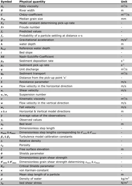
(19) Upper Stage Plane Bed in the Netherlands. December 2016. size data result in Figure 4. The blue dots in Figure 4 show all locations analysed along the Dutch river system. Figure 4 shows that the river IJssel contains the most likely location (USPB-index = 0.04). The number in the graph represents the river kilometre (RKM, indicating the location along the river) at which the most likely location is found. RKM 993.92 and the other likely locations correspond with a stretch of river just upstream of the town of Kampen (RKM 993-994). In the other rivers USPB is less likely to occur compared to the IJssel. The second most likely location is located in the river Lek near the towns of Tienhoven and Lopik (USPB-index =0.31). For the river Meuse and Bovenrijn-Waal the most likely locations are near Heusden (0.55) and near Lobith (0.41). The location near Heusden is interesting, because lower water levels than the expected levels given the observed discharge were observed here (Adriaanse, 1986), but the USPB-index does not show that this location is likely to develop USPB. All of these locations have several things in common. The grain size at those locations is small when compared to the rest of the river branch. These smaller grain sizes result in higher Suspension numbers. The Froude numbers at these locations do not show peaks and are all in the range of 0.2–0.25. More detailed information about these and other variables along the rivers can be found inAppendix A: Variables along the river. An important note to make is that the WAQUA does not simulate a plane bed. If a plane bed would occur in these extreme conditions, it will influence the results in Figure 4. This is because a plane bed allows the water to flow faster and reduce the water depth. The increased velocity and decreased water depth will increase the Froude number and the higher flow velocity will increase the Suspension number as well. The threshold obtained from Naqshband et al. (2014b) is based upon observed conditions; which means that these effects of a flat bed are included in the threshold. So the threshold could be set too high when using input data obtained without a plane bed.. Figure 4 USPB-likeliness of the Dutch rivers. HKV. CONSULTANTS. 9.
(20) Upper Stage Plane Bed in the Netherlands. December 2016. The four mentioned locations from Figure 4 are plotted in Figure 6 to be able to analyse their spatial distribution and to introduce the USPB-index. The figure shows that three of the four locations are located quite far downstream. This observation raises the question whether tidal or base water level effects do influence the conditions at these locations. Figure 5 shows that RKM 994 is just inside the discharge-dominant region, the region where the flow is dominated by the river discharge. The transition region for the Rhine-Meuse delta in the west of the Netherlands is much larger, but the most-probable locations are all in Figure 5 The Lake-dominated, Dischargedominated and the transition region the discharge dominated region. (Meergebied, Overgangsgebied and. A last important note is the exclusion of Afvoergeboied respectively) in the IJsseldelta the Keteldiep, this last stretch before the (Kroekenstoel, 2014) river IJssel ends in the Lake IJssel. A few kilometres after Kampen the river IJssel bifurcates in the Keteldiep and Kattendiep. At this bifurcation a sill is present in front of the Keteldiep in order to prevent bed load transport into the channel. This sill is implemented to reduce sedimentation to maintain navigability. This sill causes only suspended sediment to enter the channel resulting in a small grain size in this bifurcation. Since this situation does not represent the configuration in the rest of Dutch river system it is chosen to exclude the Keteldiep from any further analysis.. Figure 6 USPB-index map. 10. HKV. CONSULTANTS.
(21) Upper Stage Plane Bed in the Netherlands. December 2016. 2.2.2 Increased design conditions The analysis with the WAQUA-simulation of with discharge of 18,000 m3/s led to Figure 7. When compared to the top right of Figure 4 not a large difference can be seen, the RKMpoints show a similar pattern. The same location (Lobith, RKM 864) is the most probable location in this river branch. The USPB-index has slightly decreased, 0.37 instead of 0.41 before. This is caused by an increase in both Froude and Suspension numbers (Froude +0.01 and Suspension +0.06). This is caused by an increase in flow velocities. This decrease in the USPB-index Figure 7 USPB-likeliness in the Waal with a leads to the expectation that an analysis with discharge of 18000 m3/s at Lobith 3 a discharge of 18,000 m /s the Ijssel near Kampen will get a negative USPB index indicating that USPB will develop.. 2.3. Synthesis on the most probable locations for USPB. Under design discharge it is not expected that USPB will develop. Still a most probable location can be distinguished. The IJssel upstream of Kampen (RKM 993-994) did show the lowest USPBindex (0.03), followed by the river Lek near Tienhoven and Lopik (0.31). It was shown that an increase in discharge results in a decrease in the USPB-index. It is expected that a discharge of 18,000 m3/s by Lobith results in a negative USPB-index near Kampen. However, this analysis with the USPB-index does not give a concluding answer to the occurrence of USPB in the Netherlands due to various reasons for uncertainty. The grain size data are quite old and it could not be a representation of the current situation anymore. The water depth, flow velocity and Chézy-coefficient are all obtained from the WAQUAmodel. This model is calibrated upon historical data which do not contain the discharge scenario used in this analysis, meaning that the flow conditions are outside the range used for the calibration. The last source of uncertainty is the fact that the WAQUA-model uses the Chézy-coefficient for calibration. The Chézy-coefficient normally represents the smoothness of the bed, while calibrating upon this parameter means that the expected depth-discharge-relation, instead of the present bed form, determines the smoothness. This means that the presence of a plane bed within this discharge-scenario would not be influencing the simulated roughness. In reality the presence of this plane bed would influence the flow velocity and water depth in such a way that the USPB-index would decrease. So it might be possible that this scenario does develop USPB, but the WAQUA-model does not represent this, resulting in an USPB-index above zero. This last uncertainty asks for another approach to get an answer to the question whether USPB occurs. In the next chapter the bed form will be predicted and it will influence the depthdischarge-relation with its corresponding roughness, instead of determining the bed roughness assuming a certain depth-discharge-relation.. HKV. CONSULTANTS. 11.
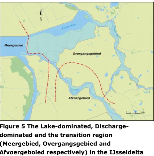
(22) Upper Stage Plane Bed in the Netherlands. December 2016. 3. Modelling dune development of flume experiments – Driving factors for USPB. 3.1. Dune evolution model choice. Modelling river dune evolution and the transition to USPB requires a model that includes several phenomena. First of all, sediment transport should be included in the model, because dune evolution is dependent on sediment transport. Both suspended and bed load transport are important in this process (Jerolmack & Mohrig, 2005; Kostaschuk et al., 2009; Kostaschuk & Villard, 1996; Nittrouer et al., 2008; Smith & McLean, 1977). Bed load transport tends to increase the dune height, while suspended transport tends to decrease dune height (Fredsoe, 1982; Kostaschuk, 2005; Kostaschuk & Best, 2005; Naqshband et al., 2014c). Along with the sediment transport, amalgamation and superposition might play a role (Ditchfield & Best, 1992). Amalgamation is the merger of dune migrating at different velocities (Martin & Jerolmack, 2013; Venditti et al., 2005) and superposition is the presence of small river dunes superimposed on larger dunes (Best, 2005). Along with the inclusion of these three required phenomena, three logistical criteria have been formulated for the model choice: Validation & accuracy, availability and computational time. This total of six criteria has been used to compare various dune evolution models. Several dune evolution models are developed in the past (Lefebvre et al., 2014; Martin & Jerolmack, 2013; Nabi et al., 2013a; Nelson et al., 2005; Shimizu et al., 2009; Van Duin, 2015). These six models are analysed upon the six criteria (Appendix B: Dune evolution models & model choice). With these six criteria it was found that the model of Van Duin (2015) is the most suitable for this study. 3.1.1 Model description The Van Duin (2015) model is based upon the model of Paarlberg et al. (2009). Which on its turn is a modified version of the process-based morphodynamic model of Németh et al. (2006), which is based upon the numerical model of Hulscher (1996). The model is a 2DV-model, which uses shallow water equations to simulate unidirectional flow. The used turbulence closure is constant eddy viscosity in combination with partial slip boundary conditions. The partial slip and constant eddy viscosity are determined by flume experiments (Paarlberg et al., 2005). The model of Paarlberg et al. (2009) uses a flow separation line (Paarlberg et al., 2007) to speed up the simulation. The version used in this study does not use this separation line (Van Duin, 2015; Van Duin et al., 2016), since the presence of this line does not represent a plane bed. The model simulates the development of one single river dune, so the domain length is always equal to the dune length. However, the model uses periodic boundary conditions; this implies that the flow at the downstream boundary of the model is used as the input at the upstream boundary. The simulated dune can be depicted multiple times in order to represent multiple dunes. The model is schematized by Figure 8. The model consists of three modules: the flow module, the sediment transport module and bed evolution module. Each of these three is described in the upcoming sub-paragraphs. The schematization on the right of Figure 8 shows the simulated dune on a sloped bed. In this figure the free surface elevation ( ), water depth ( ), bed elevation ( ) and the dune height ( ) are shown.. 12. HKV. CONSULTANTS.
(23) Upper Stage Plane Bed in the Netherlands. December 2016. Figure 8 Schematized model (Van Duin, 2015) Flow-module. A more extensive description of the flow module can be found in Van Duin et al. (2016). The momentum and continuity equations in the model are shown in equations 5 and 6: (5) (6) Where and are velocities in x and z the directions respectively, is the eddy viscosity and is the bed slope. To solve the flow equations 5 and 6 boundary conditions are needed. Three boundary conditions are given to be able to solve the equations. The boundary conditions can be found in equation 7. |. |. |. (7). These three boundary conditions represent the following: The first boundary condition implies that there can be no flow through the surface, the second represents the absence of shear stress at the surface and the third boundary condition represents the absence of flow through the bed. Along with these boundary conditions a turbulence closure is needed. A time- and depthindependent eddy viscosity is assumed, which leads to a parabolic velocity profile (Engelund, 1970; Hulscher, 1996). In order to reproduce a realistic bed shear stress along with a constant eddy viscosity a partial slip condition at the bed is necessary. This condition can be found in equation 8. |. (8). Where is the volumetric bed shear stress (m2/s2); is the flow velocity at the bed and S is the resistance parameter. The resistance parameter and the constant eddy viscosity are expressed by the following equations (equation 9 and 10) (Paarlberg et al., 2009): (9) (10) In these equations are calibration coefficients for the turbulence model. Paarlberg et al. (2009) calibrated their model to flume experiments and found that the calibration coefficients had to be set to 0.5 in order get valid simulations. Paarlberg and Schielen (2012) showed in their study that both -coefficients need to be set to 0.2 in order to make realistic river scale simulations. So to scale up the model from flume, to river scale application, it is expected to have. HKV. CONSULTANTS. 13.
(24) Upper Stage Plane Bed in the Netherlands. to reduce the stress.. December 2016. -values. This will reduce the value for. and , which reduces the bed shear. The average water depth is needed to solve the flow equations. However, the unit discharge is the input for the model. To find the average water depth an estimated initial water depth is used to start an iterative procedure. This iteration will be continued until a water depth is found which corresponds with the set unit discharge. More details for the numerical solution procedure can be found in Paarlberg et al. (2009) and Van den Berg et al. (2012). Sediment transport module. The initial model of Paarlberg et al. (2009) only considers bed load transport which is determined by the formulae of Meyer-Peter and Müller (1948). In order to simulate USPB it is necessary to include suspended load as well. Van Duin (2015) did this by introducing the sediment transport model of Nakagawa and Tsujimoto (1980). The model of Nakagawa and Tsujimoto (1980) uses a stochastic sediment-transport approach. This method uses an expression for the sediment pick up rate (equation 11) and sediment deposition rate (equation 12). ( ). ( )[. √. ] ( ). (11). Where is sediment pick up rate; F0 is a model parameter (0.03); is the specific gravity; is the Shields parameter; and is the critical Shields parameter. The deposition is determined by the following formula (equation 12): ( ). ∫. (. ) ( ). (12). Where fs(s) determines the probability of a picked-up particle to be deposited at a distance ‘s’ from the pick-up point (x-s). fs is given in equation 13. ( ). (. ). (13). Where is mean step length and s is the distance of sediment motion from the pick-up point. Since this model only gives a description for bed load transport it is not yet valid for modelling USPB. Van Duin and Hulscher (2014) incorporated the suspended load implicitly, like Shimizu et al. (2009) did. The step length is made dependent on the water depth; increasing water depth means an increasing step length. A grain which takes a long step can be seen as suspended sediment since the particle is picked up, remains in suspension for a while and settles down later. This assumption is based upon the principle that a larger water depth means there will be more turbulent vortices which, in turn, lead to sediment higher in the water column. This increased step length is the only way in which a form of suspended transport is included. This principle becomes visible in the expression of the step length of a single particle (equation 15). This non-dimensional step length is used to determine the mean step length ‘ ´ (equation 14). (. ). (14). √. The dimensionless step length of a single particle is given by the following formula (equation 15).. (. ). (15) [ {. 14. (. ). ]. HKV. CONSULTANTS.
(25) Upper Stage Plane Bed in the Netherlands. December 2016. Van Duin (2015) calibrated this step-length-model upon a synthetic dataset obtained with the more advanced model of Shimizu et al. (2009). So the model has not been calibrated upon observed dune heights. The advantage of the calibrating on the synthetic dataset was the inclusion of USPB, since there are no data available of experiments with the transition to USPB. This calibration led to the values presented in Table 3.. Entity. Value 50 350 0.5 0.8 0.116. Table 3 Sediment. The factor is important for the scaling of the model to a river scale later transport model in Chapter 4. In the current chapter the morphological module of the model will be calibrated to reproduce observed dune heights in flume experiments. parameters When the model is applied on a river scale, the step length will increase with increasing the water depth. Dividing the water depth by a reference depth, in both flume and river scenarios, the step length is standardized. Allowing the step-length-model to be applied on various water depths without the requirement to calibrate again. The dimensional step length of a particle can be found by multiplying the value for by the median grain diameter (D50). The introduction of the water depth in the equation for the step length by Van Duin (2015) might lead to non-dimensional step length values larger than the maximum step length value (250) found in the bed load experiments of Nakagawa and Tsujimoto (1980). This means particles take larger steps than the maximum step length of a particle in bed load transport. Particles that take a non-dimensional step larger than 250 are considered as suspended transport, this way suspended transport is implicitly included in the model. Bed evolution module. The functions for pick-up and deposition rates along the domain can be used to create an expression for the transport gradient along the domain, equation 16 (Van Duin et al., 2016). For each cell in the domain the amount of erosion and deposition can be calculated resulting in the gradient. ( ). ( ). (16). This transport gradient is used with the porosity and the Exner-equation (equation 17) to determine the bed evolution in each cell. (. ). (17). represents the porosity of the bed material and is usually set to 0.4.. 3.2. Model sensitivity & calibration. The model of Van Duin (2015) has only been calibrated upon a synthetic dataset made with the model of Shimizu et al. (2009). Van Duin (2015) did this in order to have a dataset that included the transition to USPB. However, the model has not been validated on observed dune heights. To validate the morphological module of the model it will be calibrated upon observed equilibrium dune heights in flume experiments (Coleman et al., 2005; Naqshband et al., 2014c). The choice to calibrate upon simulated dune height is made, because this will validate the way the morphological module simulates bed and suspended load transport. Bed and suspended load are known to increase and decrease dune height respectively. If the morphological module is capable of reproducing the observed dune heights the relative magnitudes of the bed and suspended load are valid, since they reproduce the correct dune height. Before the calibration a short sensitivity analysis of the dune height on various model parameters and natural variables is given in order to understand the effect of changing various parameters.. HKV. CONSULTANTS. 15.
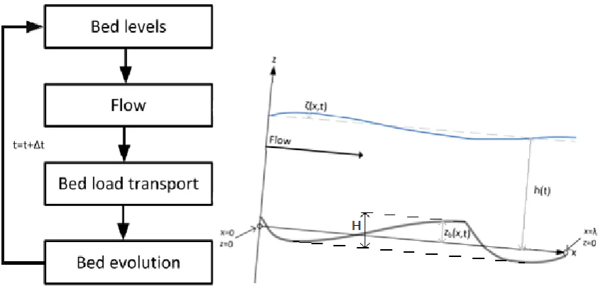
(26) Upper Stage Plane Bed in the Netherlands. December 2016. 3.2.1 Sensitivity of dune height To understand the effects of the different model inputs and Input Magnitude model parameters a sensitivity analysis has been performed. q 0.15 The entire sensitivity analysis can be found in Appendix C: i 2*10-3 Sensitivity of the equilibrium dune height. The most Duration 2 important findings in this analysis will be discussed shortly in D50 (mm) 0.28 this paragraph. The analysis has been done on model inputs, (-) 0.040 the step-length-model and the Dunelengthfactor. The model F0 (-) 0.03 inputs are assessed to get insights in dune height evolution (-) 50-350 under different conditions. The step-length-model is looked Href (m) 0.1166 into in order to be able to calibrate upon the morphological ’ (-) 0.5-0.8 part of the model. The Dunelengthfactor is a factor which can Dunelengthfactor 7 be used within the model. This factor describes the dune length as a multiplication of the water depth. The main Table 4 Base case sensitivity advantage of this approach is that using this factor avoids analysis using a stability analysis to find the dune length. This approach saves on computational time. The base conditions for the sensitivity analysis are shown in Table 4. It is a simulation of two hours of constant discharge, starting with a plane bed. Model inputs. Figure 9 shows the developed equilibrium dune height for different discharge magnitudes, different grain sizes and varying slopes. Lower discharge results in less transport and hence lower dunes, if the discharge increases dunes do not develop, because they are washed away. The grain sizes show a more interesting pattern. Grain sizes ranging from 0.20 mm till 0.75 mm show dune growth as expected. Normal dunes develop varying a few millimetres in height with along this domain. Grain sizes smaller than 0.2 mm show a different behaviour, grain of 0.15 mm are flushed away, while even smaller grains do develop dunes. No explanation is found for this. Figure 9 Sensitivity of the dune height on model inputs. 16. HKV. CONSULTANTS.
(27) Upper Stage Plane Bed in the Netherlands. December 2016. behaviour, so it has to be concluded that the model is not applicable for grains smaller than 0.2 mm. Grain larger than 0.75 mm develop smaller dunes, this is caused to the reduction in transport as these grains are less likely to be transported. The effect of increasing the bed slope is the washing away of dunes due to higher flow velocities. A small reduction in slope results in higher dune height, this is caused by the larger fraction of sediment transported as bed load instead of suspended load. Decreasing the slope even further results in a reduction in height, because the total sediment transport reduces. The step-length-model. The step-length-model is determined by the reference height, the F0-constant, the dimensionless step length and the dimensionless grain shear stress. The effect of reducing the reference height is that the dune height reduces, because the increasing step length causes more suspended transport. Increasing the reference height does not have large effects since the material in the base is already simulated with a short step-length, representing bed load. The effects of the F0constant are straight forward. Increasing the value will result in more transport and higher dunes while reducing does give the opposite result. Figure 10 explains the step-lengthmodel-principle. The minimum and maximum points are defined by and . The main principle of the step-length-model is that when the step length is large, particle transport can be seen as suspended transport. The -value is determined by the flow and sediment characteristics and is translated to the step length using the graph below. So changing the coordinates of the maximum and minimum will result in another model. If the red line shifts up by these changes (increase in -values or a decrease in -values) the Figure 10 Step-length-model-principle (Van Duin, overall step length increases, 2015) – red line represents model used in this study resulting in more suspended transport. This results in lower dunes. Changing these four values vice versa will result in a decrease in step length, more bed load transport, hence higher dunes. It is important to note that changing the model such that the graph becomes extremely steep all dune development is suppressed. This is caused by the fact that nearly all sediment in this case will be transported in suspension. Dunelengthfactor. The Dunelengthfactor did not show large variations in the resulting dune height. When the factor was set to 5 no dunes did develop. This does not pose a problem since the dune length is about 7 times the water depth (Paarlberg et al., 2009). Therefore, a Dunelengthfactor of 5 is not realistic to use and the factor will be set to 7. In order to check the validity of using the Dunelengthfactor simulations with the stability analysis are made as well. This did not lead to large differences in the resulting equilibrium dune height. However, it proved to be usable in the scenarios where the model experienced stability issues.. HKV. CONSULTANTS. 17.
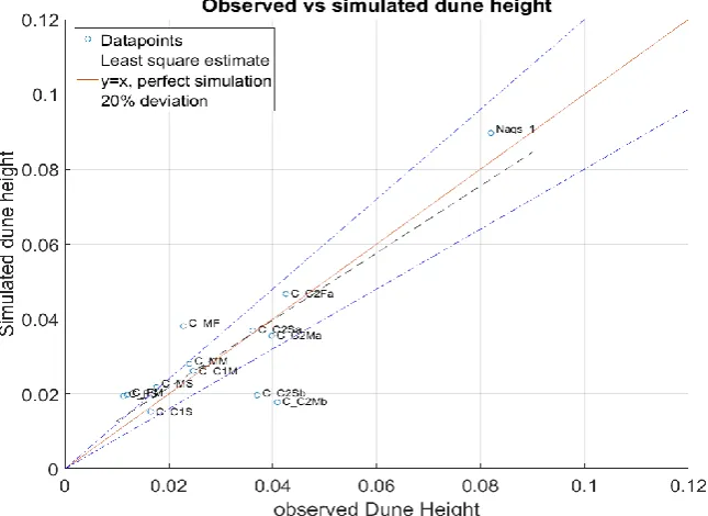
(28) Upper Stage Plane Bed in the Netherlands. December 2016. 3.2.2 Calibration The insights of the sensitivity analysis have been used in the process of calibrating the model. The model is calibrated upon 17 flume experiments that use a constant discharge to develop an equilibrium dune height. 15 experiments of Coleman et al. (2005) and 2 from Naqshband et al. (2014c) are used (more details on these experiment in Appendix D: Flume experiments used for calibration). The. target of the calibration is to validate the morphological module of the model. The target of the calibration is to achieve an Nash-Sutcliffe-value (NS) for the observed and simulated dune heights of at least 0.7, see equation 18 (Nash & Sutcliffe, 1970). Along with this calibration on the morphology the hydrodynamic conditions have to be realistic as well. So the simulated and observed water depths and flow velocities will be analysed as well, again with the NS-value. ∑( ∑(. ) ̅). (18). Where are the observed values, are the predicted values by the model and ̅ is the average value of all observations . A NS-value of 1 represents a perfect simulation, where a value of 0 or a negative value means a better prediction can be given by using the mean of the observed values. Observed and simulated dune heights New Figure 11 shows the results of the calibration. The NS- Parameter Old value for the simulated dune height is 0.69. This has Href 0.1166 0.1166 been achieved by adjusting the step-length-model as & 50 & 350 50 & 400 shown in Table 5. This NS-value of 0.69 does not & 0.5 & 0.8 0.35 & 0.8 exceed the targeted value of 0.7. Still the calibrated F0 0.03 0.03 model is considered accepted, because it reproduces dune with height in a realistic order of magnitude. An Table 5 Updated step-length-model important note is that Figure 11 only shows 13 simulations while 17 simulations were made for the calibration. Four simulations did not develop any dunes. These simulations have been removed from the calibration process.. Figure 11 Results calibration morphological model (the codes represent the various experiments, see Appendix D) 18. HKV. CONSULTANTS.
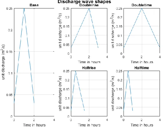
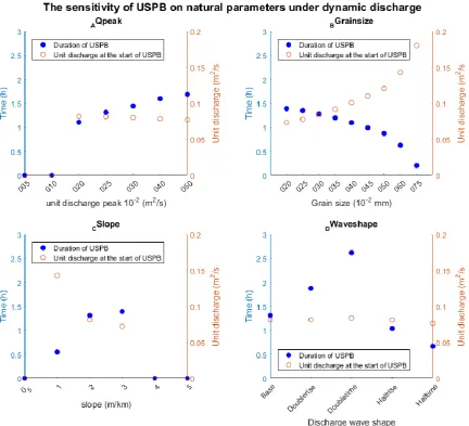
(29) Upper Stage Plane Bed in the Netherlands. December 2016. The hydrodynamics are also assessed. The NS-value for the water depth was found to be 0.76 and for the flow velocity 0.73. These values indicate that the simulation of the hydrodynamics is realistic as well. Considering both the morphodynamic and hydrodynamic results these settings for the morphological module are considered acceptable for the further analyses.. 3.3. Driving factors for USPB. To find the most important parameters for USPB, the calibrated model is applied under various conditions and the development of USPB will be assessed. This analysis will be another sensitivity analysis. This sensitivity analysis focuses on the occurrence and duration of USPB under a dynamic discharge. The base scenario is a two hour long discharge peak shown in Figure 12Base. This discharge scenario is based upon scenario A4 in Shimizu et al. (2009). This is the scenario Van Duin (2015) used to reproduce the plane bed results with his model. The standard bed slope used in this sensitivity analysis is 2*10-3 (-) and the grain size is 0.28 mm. To find the driving factors behind USPB, the four variables used as input have been varied. These four variables are the magnitude of the peak, the bed slope, the grain size Figure 12 Discharge waves used to analyse USPB and the shape of the discharge wave. The first three variables can be described by magnitudes, which have been increased and decreased to analyse the influence of these variables. The discharge wave shapes analysed are shown in Figure 12. These five shape are chosen because Shimizu et al. (2009) showed that the steepness of the rising and falling limbs of the discharge wave might affect the development of USPB. 3.3.1 USPB development under various conditions Figure 14 shows the occurrence of USPB in the different scenarios. The blue axis on the left shows how long USPB was present within the simulation. In red it is shown what the discharge was when USPB started to occur. Figure 14 ‘AQpeak’ shows that USPB starts to occur when the unit discharge is above roughly 0.08 m2/s. The duration increases when the peak height increases, since the unit discharge is above 0.08 m2/s for a longer period. These observations. HKV. CONSULTANTS. Figure 13 Dune field and dune height over time. 19.
(30) Upper Stage Plane Bed in the Netherlands. December 2016. indicate that USPB occurs when the unit discharge is 0.08 m2/s or higher. However, the scenario where the unit discharge peak is 0.10 m2/s does not develop USPB. The detailed results (Figure 13) show that this discharge wave indeed resulted in a reduction in dune height (t ≈ 3000s-5000s), but this period of dune reduction was not long enough to achieve plane bed, the entire reduction to a plane bed takes approximately 20 minutes. Hence, along with the threshold value, the period during which this value is exceeded is important for the development of USPB as well. So in order to develop USPB the peak discharge should be high and long enough.. Figure 14 USPB-development under various conditions. The different grain sizes in Figure 14 also show the development of USPB. The smaller the grain, the longer the duration of USPB. The required discharge level is also lower when the grain size is smaller, because the smaller the grain the earlier it is transported in suspension. The USPB-development under different bed slopes shows a less straight forward pattern. A slope too gentle does not develop USPB under this discharge wave. When the bed is steeper USPB does develop. The discharge required is lower when the bed is steeper, this can be explained by the higher flow velocities which transport more sediment in suspension. The two steepest slopes do not develop USPB, in these two cases the flow velocities are too high for dunes to develop in the first place.. 20. HKV. CONSULTANTS.
Figure


+7
Related documents
© American DJ Supply ® - www.americandj.com - Revo Rave User Manual Page 12 With this feature you can connect the fixtures to one another using the IEC input and
Furthermore, while symbolic execution systems often avoid reasoning precisely about symbolic memory accesses (e.g., access- ing a symbolic offset in an array), C OMMUTER ’s test
This dataset is assessed using [1] exploratory spatial analysis to determine the degree of spatial variation in HEV registrations, [2] area classifications to consider if
Esta publicación es el fruto de un trabajo desinteresado para mis amigos, los miembros del foro. Todos ellos pueden obtener gratis esta obra y otras con la condición de publicar
Soleamani, “A New Online Signature Verification System Based On Combining Mellin Transform, Mfcc And Neural Network,” Digital Signal Process., Vol. Wigdor, “Typing On Flat
2.11 Zoals onder 2.7 overwogen heeft de staatssecretaris de aanvragen van de stichting onder verwijzing naar artikel 6, aanhef en onder e, van de Subsidieregeling ESF-3, artikel
In fact, the children increased their use of spontaneous commenting, looks to the parent, and positive affect while on the computer and decreased their inappropriate language
Manager - Regulatory Accounting & Compliance El Paso Electric
