Location-based refurbishment planning in complex
environments under ongoing operations
Master thesis: Construction Management & Engineering
MARK JANSSEN 2
Report
Title : Location based refurbishment planning in complex environments under ongoing operations
Part : Final report
Date : 15-9-2014
Contact information
Author : Ing. J.M. Janssen (Mark) Student number : s1372556
Email : [email protected]
Phone : +31 6 51 83 20 68
Educational institution : University of Twente
Faculty : CTW
Program : Construction Management & Engineering Address : Drienerlolaan 5
7522NB Enschede First supervisor : Dr. T. Hartmann
Email : [email protected]
Second supervisor : Dr. S.H. Al-Jibouri
Email : [email protected]
Host organization : Luchthaven Schiphol Department : A / ASM / TRE
Address : Evert v/d Beekstraat 202 1118CP Schiphol
Supervisor : Ir. A. Worp
MARK JANSSEN 3
location breakdown structure, which is a core concept within location based planning, remains unstructured. This thesis presents a method for the design of a location breakdown structure for complex refurbishment projects while remaining operational.
The proposed method was developed based on existing knowledge in location based planning. The proposed method has been tested on an example refurbishment project at an international airport, which has led to an increase in the quality and level of detail of the method.
The method starts with identification and categorization of constraints that have to be taken into account during construction. After that the project is split up in locations in a top-down approach, based on the existing and new design. This results in a hierarchical location breakdown structure that, together with the schedule, forms a location based project plan.
It was found that the method is helpful in the design of a location breakdown structure for projects in complex environments, like the case project. A sound trade-off between feasibility of construction activities and availability and accessibility for the client is made by using the developed method while taking into account the environmental constraints.
Acknowledgements
MARK JANSSEN 4
1. INTRODUCTION ... 5
2. THEORETICAL POINTS OF DEPARTURE ... 7
2.1. LOCATION BASED PLANNING ... 7
2.2. THE LOCATION BREAKDOWN STRUCTURE ... 8
2.3. DEFINING LOCATIONS ... 9
2.4. CONCLUSION... 11
2.5. GOAL ... 12
3. RESEARCH METHOD ... 13
3.1. DEVELOPING & VALIDATING THE METHOD ... 13
3.2. THE CASE PROJECT ... 15
4. METHOD DESCRIPTION ... 18
4.1. STEP 1–PROJECT ANALYSIS ... 20
4.2. STEP 2–PLAN ACCESS ... 22
4.3. STEP 3–PLAN RESOURCE FLOW ... 23
4.4. STEP 4–PLAN DETAIL & FINISHES ... 25
4.5. STEP 5– PLAN ANALYSIS ... 26
5. ILLUSTRATION OF THE METHOD ... 28
5.1. PROJECT ANALYSIS ... 28
5.2. PLAN FLOW ... 30
5.3. PLAN RESOURCE FLOW ... 32
5.4. DETAIL & FINISHES ... 33
5.5. ANALYSIS ... 34
5.6. RESULTS ... 35
6. VALIDATION ... 40
7. DISCUSSION, LIMITATIONS & FURTHER RESEARCH ... 42
7.1. DISCUSSION ... 42
7.2. THEORETICAL CONTRIBUTIONS ... 43
7.3. PRACTICAL CONTRIBUTIONS ... 44
7.4. LIMITATIONS OF THE METHOD: ... 45
7.5. FURTHER RESEARCH ... 45
MARK JANSSEN 5
1.
Introduction
Nowadays construction projects are changing, more and more construction projects involve refurbishment in the built environment. Sometimes the building that is under construction continues to be in use during construction. This causes difficulties in the development of a good schedule for this type of projects.
As an alternative to activity based planning, the location based planning method has proven its value in the past (Kala, Seppänen, & Stein, 2010) (Andersson & Christensen, 2007). In this method a construction project is broken down into locations that are organized in a location breakdown structure instead of activities that are organized in a work breakdown structure. However, existing literature only focuses on new built projects instead of refurbishment projects. Also knowledge on how to break down a project into locations is still lacking.
MARK JANSSEN 6
This thesis describes the development of a method for the design of a location breakdown structure for refurbishment projects in complex environments. This method enables construction planners to develop a location based project plan that enables a contractor to execute construction activities while facilitating the client’s needs. The method can be applied to refurbishment projects that have to be executed while the building stays operational, for example a refurbishment of a shopping centre or an airport terminal.
MARK JANSSEN 7
2.
Theoretical points of departure
To put this research in context, this chapter gives an overview of the existing literature that is related to the research described in this report. In this way, this literature overview provides the theoretical points of departure for the developed method that is described in the next chapter.
This chapter starts with the explanation of location-based planning. Then it goes in further detail regarding one specific element of location-based planning, which is the location breakdown structure. The subsequent paragraph describes the existing knowledge of defining the parts of that location breakdown structure. These three paragraphs describe the existing knowledge and experience on location based planning. The fourth paragraph concludes this with the identification of the gap in the described literature. The last paragraph of this chapter defines the objective for this research that was set to contribute to the existing literature and forms the starting point for this research.
2.1.
Location based planning
In the past several studies were conducted into space management in construction projects. Akinci (2000) identified 4 approaches to space management in construction. One of these is the Line of Balance approach. The Line of Balance approach is a refinement of bar charts and focuses on monitoring the current status of an activity relative to its scheduled status (Halpin & Riggs, 1992) . In this approach a construction project is divided in zones to which one construction crew is assigned at a time. In this way time-space conflicts during construction are prevented and synchronization of the paces of the different crews can optimize resource flow (Björnfot & Jongeling, 2007).
MARK JANSSEN 8
Building
floor
apartment apartment
floor
apartment apartment locations are important in construction because building is rarely an exactly repetitive process. It looks more like a series of physical locations in which work of variable type and quantity must be completed with the consequent benefit of taking on a physical reality as well as organizing the work on site (Kenley & Seppänen, 2009).
In the past, the location based scheduling system is successfully applied in a number of studies. For example, location-based scheduling resulted in improved project control and establishment of continuous flow of resources trough locations (Andersson & Christensen, 2007). Kala et al. (2010) applied an integrated model in combination with a location-based planning system in constructing the foundations of a large hospital construction project. A 3D provided a basis for quantity take-off as a basic ingredient for a location-based schedule. It was found that this system resulted in more schedule optimizations over traditional CPM based approaches and resulted in shorter overall duration with more continuous resource use.
These examples show that, although activity based planning is more widely used, location based planning is a suitable approach for the creation of a project schedule.
2.2.
The Location Breakdown Structure
A Location Breakdown Structure is defined as a “theoretical and hierarchical description of a project and allows schedulers to allocate and group activities or tasks across locations” (Büchmann-Slorup, 2012).
As explained in the previous paragraph, Location-based scheduling requires the decomposition of a project into locations. These locations are then organized in a
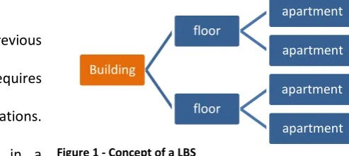
[image:8.595.254.501.566.676.2]hierarchical Location Breakdown Structure (LBS). This is in fact a physical breakdown of the project in locations for which a construction sequence is determined later on. A schematic example of the LBS concept is shown in Figure 1.
MARK JANSSEN 9
In standard projects, like the construction of an apartment complex, the LBS is obvious. The top level includes the building, the next level represents each floor separately, and the third level contains all the separate apartments and so on.
However, in special projects the LBS will not be that obvious (Kenley & Seppänen, 2009). For example large open spaces can be split up in many different ways, or next to the physical reality ongoing operations add an extra dimension that has to be taken into account. As Büchmann-Slorup (2012) states, the hierarchical aspect results in the one requirement for a LBS, which means that the top level of the LBS has to include every sub-location of the project. Beyond this, a project can be broken down in any suitable way.
2.3.
Defining locations
Although it is argued that a project can be broken down in any suitable way, there is no specific research into the design of a location breakdown structure. During the research into location based planning only some drivers and guidelines for this were found. These are presented in this paragraph. First some main ‘drivers’ that are related to the spatial distribution of locations in a construction project are described, followed by guidelines for the definition of locations.
2.3.1.Drivers of LBS design
First thing to look at in the design process of a LBS is the type of project. In greenfield projects the definition of locations on the highest hierarchy level focuses on identifying structural independent parts like different towers that are part of an apartment complex. Defining these as separate locations has advantages for the contractor. It enables him to optimize construction sequence and deliver the independent parts separately.
MARK JANSSEN 10
building for the client and contractor both in order to organize the work on site (Kenley & Seppänen, 2009).
The middle and lower level are focusing on planning the construction activities within the defined overlying level. The middle levels in the location hierarchy are used to plan production flow of structures, the lowest level focuses on planning detail and finishes. This also means that constraints that have to do with the environment of the project, have to be taken into account from the highest level of the location breakdown structure. Other planning constraints are coming in during scheduling the lower levels.
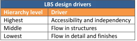
[image:10.595.179.419.365.437.2]The identified drivers for each level in the location breakdown structure are categorized in Table 1 below.
Table 1 - LBS drivers
LBS design drivers
Hierarchy level Driver
Highest Accessibility and independency Middle Flow in structures
Lowest Flow in detail and finishes
Summarizing, a location breakdown structure should be designed in a way that enables the contractor and the client to meet their requirements. The contractor should be able to do his work, while the client’s needs are fulfilled as well.
2.3.2.Guidelines for picking locations
MARK JANSSEN 11
Most of the guidelines on the LBS design relate to the characteristics of the building that has to be constructed or refurbished:
The LBS of schedules is often based on the spatial distribution of the final product, but this
distribution might not be applicable for all types of construction work (Jongeling, 2006).
Defining locations should be based on physical demarcations (Jongeling, 2006)
Large open spaces should be divided into smaller locations, between which logic relations are
defined (Kenley & Seppänen, 2009)
Same as in the drivers for the different hierarchy levels that are described in the previous section, the exact influence of the guidelines for the definition of locations also differ per project type. However, a common characteristic is that a LBS should deal with the constraints that occur in the project and that it utilises the greatest project opportunities.
2.4.
Conclusion
Location based scheduling has already proven its value in construction theory and practice. Examples of successful use of location based scheduling are given in previous sections. However, although there is quite some research into location based scheduling available, none of the available studies provide knowledge on how the LBS was defined. So far, only drivers and guidelines are identified. Research in how to determine the location breakdown structure is still missing.
MARK JANSSEN 12
2.5.
Goal
To aggregate the existing knowledge and provide a supplement to existing literature, the following objective was set for this research:
“To create a method that supports construction planners in the design of a location-based project plan that leads to a successful project execution in complex construction environment.
MARK JANSSEN 13
3.
Research method
This research complements existing literature on location based scheduling, especially with regard to the literature gap as identified in the previous chapter.
This research was designed as a case study. This means that a construction project was studied in depth (Leedy & Ormrod, 2013) and used to develop the method to design a location breakdown structure for complex refurbishment projects under ongoing operations. Case study research is appropriate because a case study addresses the holistic nature of real-world contexts in which phenomena occur and shed light on largely unexplored phenomena (Eisenhardt, 1989). This holistic approach is of high value because in a construction project like in this research, there are a lot of scheduling issues that offer the opportunity to show the value of location based planning. Therefore this project is suitable for the development of a method that is going to be applied in location based scheduling for complex refurbishment projects under ongoing operations.
This chapter provides a description of the executed research steps that led to the developed method. After that a description of the case project is provided.
3.1.
Developing & validating the method
During the literature review some drivers and guidelines for the design of a location breakdown structure were already discovered. These drivers and guidelines provided the first guidance for the development of the method and were therefore used as starting point.
MARK JANSSEN 14
that developed the construction plan for the case project as it was applied in reality. The interviews were mainly used to get context on the obtained information from the previously described documents and to obtain information about the current practice for the development of these project plans and on the identification of key performance indicators for schedules of the case project. These KPI’s were required further in the process in order to assess location based project plans that were made using the method that was developed in this research. A report was made of each interview afterwards. In order to check whether the research had captured and presented the provided information correctly, this report was sent to the interviewee for his or her to check the contents. Sometimes the interviewee added information that they did not think about during the interview, or a misunderstanding by the researcher was corrected in this feedback round. After the feedback round the interview report was finished. In this way reliable interview data is obtained.
In order to design location breakdown structures and analyse these, a tool was developed by the researcher. This tool consists of Autodesk Revit, a 3D modelling software package that was used to analyse the design of the construction project. The location breakdown structures were drawn in area plans in the 3D model using Revit. In this way the designed location breakdown structures could be exported easily into a spreadsheet. This spreadsheet was built by the research and used to define construction schedules based on the designed location breakdown structures. This spreadsheet also provided information on the defined KPI’s in order to assess the designed location based project plans.
MARK JANSSEN 15
In the last step the method was validated. The application of the method on the case project already provided a basis for validation because it was already applied in a real environment. Further validation was realised by using expert opinions. A session was organised to which experts were invited. The first participants were selected from the team that is actually involved in the refurbishment of the case project. Because these people have knowledge about the progress of the project they can identify strengths and weaknesses of the method by comparing it to the reality in which they are working. Next to the involved people in the project a project manager that was involved in another project of which the execution plan was in an earlier stage was also present. In this way the applicability of the method to other projects could also be assessed by experts.
During the validation session the method was presented and applied on the case project step by step. After the presentation the method and results were discussed by the researcher and the experts. The validation is described in more detail in chapter 6 of this report. This is done because the description of the validation would make more sense when the method that was developed in this research is known to the reader.
3.2.
The case project
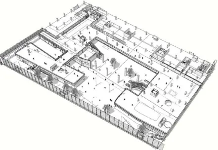
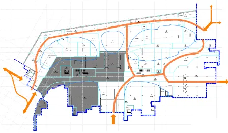
The refurbishment of Lounge 2 at Amsterdam Airport Schiphol was used to test and evaluate the developed method. This lounge is one of the three shopping areas after the passport check and is currently undergoing a major refurbishment because of the switch to central security at the airport. Due to this switch, access points are going to change as well as the flow paths of the 14 million people that travel through the lounge annually (Schiphol, 2012). A plan layout of this project is shown in Figure 2.
MARK JANSSEN 16
To get a sense of the size of the project, the total floor area of the project is 15,875m2
[image:16.595.78.520.237.541.2](Benthem Crouwel Architekten, 2013). Because the airport operations have to continue at any time, the lounge will also be in use continuously. The construction period will last from September 2014 to the end of 2015.
Figure 2 – Lounge 2 (source: (MAAKMAAR, 2013))
MARK JANSSEN 17
To measure the quality of construction plans during the research, a number of key performance indicators that are relevant in this project were defined by interviewing two project managers and one stakeholder that had a role in the development of the designed schedule for this project. These KPI’s are summarized and shown in Table 2.
Table 2 - KPI's refurbishment Lounge 2
KPI’s Refurbishment Lounge 2
Area availability for: Measured by:
Flow m2
Retail m2
Hospitality m2
Hospitality sitting m2
Free sitting m2
Others: Measured by:
Resource usage # crews
MARK JANSSEN 18
4.
Method description
Using the previously identified drivers and guidelines for the design of a location breakdown structure and the available data from the case project, a method was developed that provides the required steps to design such a location breakdown structure for refurbishment projects in complex environments under ongoing operations. This method is explained in this chapter.
The focus on complex refurbishment under ongoing operations is because this kind of projects has to deal with existing situation of the project and the new situation that has to be realized by construction. This new designed situation also has to be realized within constraints that are imposed by the client’s activities. The proposed method helps project planners in planning this kind of projects by providing concrete steps that are leading to a location based project plan that deals with these ingredients.
MARK JANSSEN 19
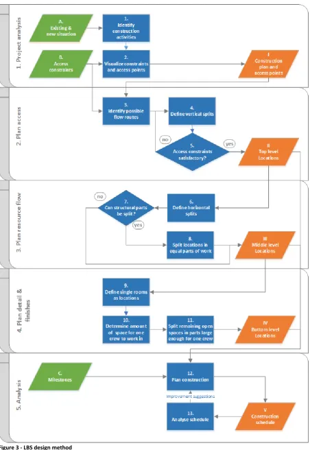
MARK JANSSEN 20
4.1.
Step 1 – Project analysis
The goal of the first step is to analyse the project and constraints as a whole. This means that the information that is required to make a feasible location based project plan has to be gathered and ordered in a way that provides a sound basis for the required subsequent steps in the method.
First input is the design information of the project (A), including the existing and new situation. Both situations are required in order to identify the construction activities (1) that are required to transform the building from the existing situation into the designed one. Focus will be on major activities and not small detailing or finishing activities, depending on how easy it is to split these activities according to locations. However, it is important to have a good overview of the required activities because further in the process the project has to be split in locations, this should cause the least possible inconvenience for the execution of construction activities.
In this view the activities that affect the structural elements of the building are most important. It is often difficult and inefficient to split up the construction of structural elements like concrete floors, especially when a time gap between the realisations of the separate parts is on the schedule. For example, when a concrete floor has to be poured, it is probably more efficient to do this in one pour than to split it up in parts. Therefore, structural elements are important to take into account in the design of locations. Additionally, building structures like columns and floors are often designed as a whole and are vital in maintaining the structural safety of the building. Therefore splitting these structures in parts may result in additional measures to guarantee structural safety during construction. When this can be prevented by designing locations in a way that this is not required, a higher efficiency will be realised.
MARK JANSSEN 21
operations in warehouses that are continuously in use, people flows in a shopping centre or at an airport where people need to reach their destination experiencing the least possible disruption.
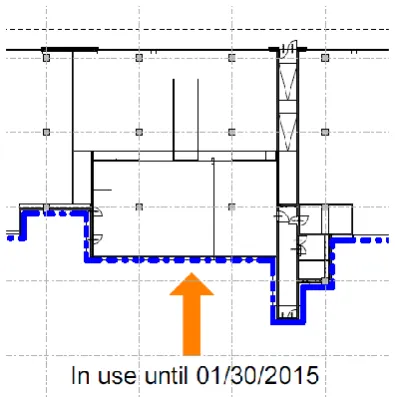
To get oversight in the relevant constraints and construction activities, the constraints have to be visualised in the construction plans (2). This can be done in a 2D floor plan that shows the design of the old and new situation at the same time. Figure 5 and Figure 4 show examples of visualized access points in a floor plan, which form a constraint because these need to be available during construction. Figure 5 shows an example of an access point that needs to be available the whole time, while Figure 4 shows an access point that closes at a certain date because of external reasons.
[image:21.595.71.523.292.549.2]When these steps are finished, the starting point to design a location breakdown structure is finished (I). A plan including the layout of construction activities and access points that have to be reachable at any time provides the information that is required to start designing a location breakdown structure in a clear and structured way.
[image:21.595.329.527.316.515.2]MARK JANSSEN 22
4.2.
Step 2 – Plan access
The goal of this second step is to define the locations in the top level of the location breakdown structure. The design of this level is driven by accessibility. Therefore this step focuses on splitting the project in the least possible locations, from which maximum one can be in use at the same time without diminishing the accessibility of the area (II).
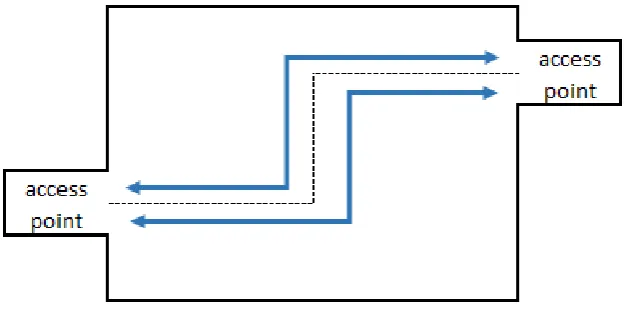
[image:22.595.141.457.429.585.2]To come to this top level, first the possible flow routes have to be identified (3). Because all the floor area within the project demarcation will become under construction at a certain point in time, the access points that have to stay in use are split in 2 parts. This ensures that one part of each access point can stay in use while the other is in the construction area. In this way accessibility during construction is ensured. Subsequently lines are drawn that connect all access points to each other without splitting the required structural activities. These lines represent the possibilities for logistical flows during construction. A schematic example of this step is shown in Figure 6. In this figure access points are split up and possibilities for logistical flows are shown.
Figure 6 - logistical flows based on access points
MARK JANSSEN 23
between the previously identified traffic flows in order to maintain at least one way to reach all access points during construction.
Because the definition of the locations on the highest level has to deal with a lot of important things at the same time, this is a very complex step to conduct for a construction planner. Therefore an extra check is required to make sure that the execution of construction activities is feasible and passenger flow and access is maintained at any time (5). This check determines whether the defined locations have to be adapted or if they are good enough to be used as a basis for the rest of the project plan.
4.3.
Step 3 – Plan resource flow
While In step 2 locations are defined that take into account the accessibility. The goal of the third step is to define the locations in the middle levels of the location breakdown structure (III). The design of this level is driven by the planning of production flow. This step therefore focuses on splitting the previously defined locations further to a level that can help the planner to assign resources to and achieve flow or duration cuts by doing so. A schematic example of this purpose is shown in Figure 7.
MARK JANSSEN 24
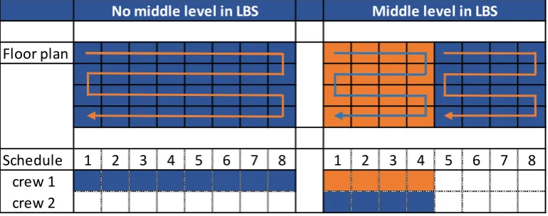
[image:24.595.106.491.224.376.2]When a location from the highest level is first split up in large parts, a corresponding number of starting points are designed. In this way there is not one row of crews that flows through locations starting from one point, but there are more starting from different points. There will be more resources required at the same time and the duration of the project will be reduced. Achieving flow in this way is the purpose of adding a middle level in the location breakdown structure.
Figure 7 - Purpose of middle level in LBS
In order to define these middle level locations, first the horizontal splits of the previously defined locations have to be defined (6). This is required for projects that include more than one floor level because there will be no activities that involve all floors at the same time. Therefore horizontal splits are a good start in creating several starting points for activities within a previously defined location.
When horizontal splits are defined, the planner has to check whether structural parts can be split and constructed separately (7). This is relevant because within location based planning there is only one crew working in a location at a given time. So when the activities that are planned on this level can be split, more crews can be assigned at the same time and the required time will decrease. Whether it is possible to split these activities depends on the project and construction methods, therefore this decision requires project specific information.
When structural parts are not present or cannot be split, the horizontal zones are defined as middle level locations (III). It is easy to assign activities to each horizontal zone separately because it is possible to work on separate floors at the same time without disturbing each other.
Floor plan
Schedule 1 2 3 4 5 6 7 8 1 2 3 4 5 6 7 8
crew 1 crew 2
MARK JANSSEN 25
When structural parts can be split, the splits should be defined in a way that the amounts of work required for the structural parts are more or less equal (8), as far as possible. In this way the highest flow advantage will be achieved. For instance, when a location is split up in one part that contains 90% of the work, applying a split does not make sense because the advantage of splitting this element will be very little in terms of project duration. A rule of thumb in splitting locations in equal parts of work is to split the area that is involved in the activities should be taken into account. When these areas are split more or less equally, the related work will also be split more or less equally as well.
4.4.
Step 4 – Plan detail & finishes
The goal of this fourth step is to define the locations in the lowest level of the location breakdown structure (IV). This level is meant to include locations that are only large enough for one crew. Therefore the previously defined locations are split further into small locations to which activities for one crew can be assigned and no further splitting is required.
The first step is to define single spaces in the new design as locations (9). This helps in providing a clearly defined and safe working environment for one crew because there will be only one crew working in a room at the same time, so crews will not hinder each other.
After defining rooms as locations, there are sometimes open spaces around these rooms that are not considered to be rooms left to split up in locations. These open spaces need to be split up in order to keep insight in which location is in use and which one is not; and to maintain a flow of crews that is working its way through locations. When large spaces are not split up they may seem in use for some kind of activity, while that activity only takes place in a small part of that location. Based on the principle that one crew works in one location at a time, the amount of space that is required for one crew to work in is determined by the planner (10).
MARK JANSSEN 26
project, locations will be finished very quickly. In that case the size of locations can be based on the daily production of a crew, so a crew can work its way through the locations finishing one per day. When more work is required, locations may be defined smaller in order to be able to assign more resources and still maintain flow.
The project planner has to determine an amount of area based on project specific information. This number is then used to split up the remaining open spaces up in locations suitable for one crew to work in (11).
At the end of this step, all locations are defined. In fact, a hierarchical location breakdown structure is designed by working through a top-down approach of splitting locations further and further. But in order to check the quality of the plan it should be evaluated. Therefore one more step is added that is described in the next and last section.
4.5.
Step 5 – plan analysis
The goal of this step is to create a schedule based on the designed location breakdown structure (V), in order to check its quality and suitability for the specific project it is applied to.
To create and evaluate the location breakdown structure new input is required. In order to create the schedule milestones like start date, end date and possibly some other milestones that influence the schedule have to be known (C). These other milestones can, for example, be related to separate delivery of some locations that can affect the sequence or the pace in which locations have to be finished.
MARK JANSSEN 27
required resources would be available. When all locations are put on the schedule according to relations and milestones, a location based construction schedule will be the result (V).
MARK JANSSEN 28
5.
Illustration of the method
This chapter describes the application of the developed method to the case project. The goal of this section is to show how this method worked out in practice on a real construction project. Thereby showing the usability of this method in the challenge of designing a location-based project plan for projects that have to be executed in complex environments.
This chapter is structured according to the method as presented in the previous chapter. Each paragraph describes the steps that were taken by the researcher for one of the 5 steps of the method. The last paragraph presents the results of the method for the case project, the refurbishment of Lounge 2 at Amsterdam Airport Schiphol. Because of the size of the project the explanation sometimes uses schematic examples. Drawings of the real situation that were used or made during the research are added in the appendix.
5.1.
Project analysis
Step 1: The 3D model of the case project included the existing situation and the designed situation. This information was used to identify the changes in structure and interior that transform the project from the existing situation into the designed one. Identification of the structural changes was the most important thing in this step, because this has the largest influence on the definition of locations.
MARK JANSSEN 29
floor as well. By highlighting changes to structure in different colours, an overview of all structural changes is created and presented in an easy understandable way.
To identify the interior changes the objects that are removed, new built or not affected at all were highlighted in different colours. Together with the highlighted structures in both old and new situations, an overview of all the activities that are required was created. In this way all information regarding the objects involved in construction activities was presented in one organized drawing. The result of this process is shown in the drawing in appendix A.
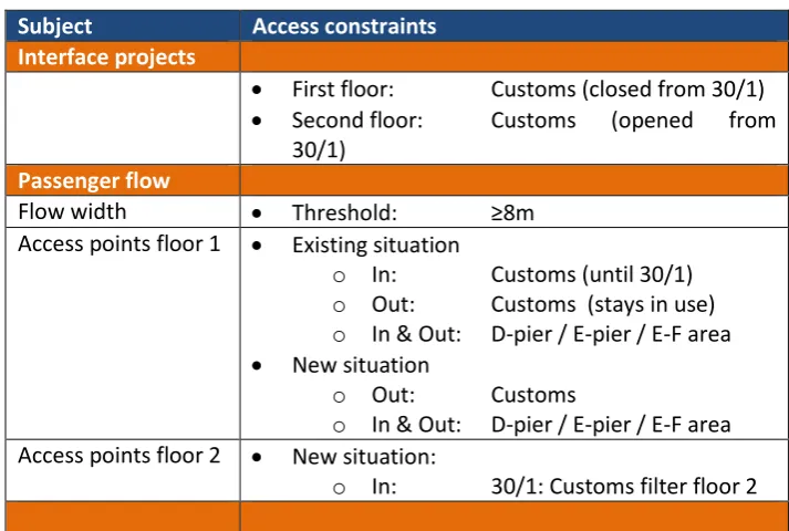
[image:29.595.118.475.522.762.2]Step 2: Information on passenger flows at the airport and existing project plans were analysed in order to identify the access points and other constraints that were relevant for the definition of locations. Because these constraints come from different sources they were first ordered, which is also shown in Table 3. After having this insight in the accessibility constraints, these were visualised in the same floor plan in which activities were identified in the previous step. Per access point is indicated whether it has to stay available the whole time or if it is going to be closed or opened. The result of this step is a set of drawings of both floors of the project, including highlighted structures and marked access points. These drawings can be found in appendix A of this report.
Table 3 - access and flow constraints
Subject Access constraints
Interface projects
First floor: Customs (closed from 30/1)
Second floor: Customs (opened from 30/1)
Passenger flow
Flow width Threshold: ≥8m
Access points floor 1 Existing situation
o In: Customs (until 30/1)
o Out: Customs (stays in use)
o In & Out: D-pier / E-pier / E-F area
New situation
o Out: Customs
o In & Out: D-pier / E-pier / E-F area Access points floor 2 New situation:
MARK JANSSEN 30
5.2.
Plan flow
Step 3: In order to facilitate passenger flows at all times during construction, the possibilities for these flow are identified. Because all the floor area of the project will be under construction at a certain point in time, the access points were split up and marked by a letter and number combination. Access points were first given a letter, the splits are identified by adding a number to that letter.
Splitting access points was necessary in order to ensure that at least one part of the access points is available for the passenger flows. The splits themselves are based on maximizing the available flow width during construction, therefore access points are divided in equal parts.
[image:30.595.70.519.452.713.2]Two access points did not require splitting, because one is going to be closed during construction because it is replaced by the other access point that did not need to be split. Therefore these access points are completely included in one location, which results in a requirement for the construction schedule. Namely that one needs to be available until a certain point in time, and the other needs to be finished before it is opened.
MARK JANSSEN 31
The options for passenger flows were determined based on the identified structural activities by drawing flow lines in the floor plan connecting the access points to each other while causing the least possible splits in the structural activities that were already identified and visualised in the previous steps. These flow lines represent possibilities for the passenger flows during construction and are therefore very important in the definition of locations. An example is shown in Figure 8.
Step 4: Using the possibilities for the passenger flows during construction that were drawn in the previous step, the vertical split of the project into locations was defined. The goal is to define the least possible locations without blocking access points or passenger flows. Therefore the splits in the access points were used as starting points for drawing the borders of the locations.
Based on the identified possibilities for passenger flows through the project area the borders for the locations were drawn in the floor plan extracted from the 3D model. This resulted in 3 different locations that form the top level of the location breakdown structure. These locations are regarded as the 3 phases in construction because when more than one location is under construction at the same time, access points will become unavailable.
When the borders were finished, locations are given a number in a random sequence by which they are identified in the rest of the process.
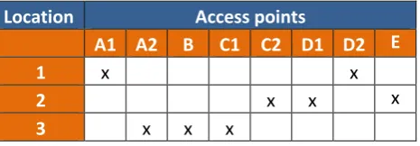
Step 5: Because accessibility is the key driver of the definition of locations in the previous step, a check was conducted in order to make sure that the passenger flows will not be blocked during construction.
MARK JANSSEN 32
[image:32.595.183.416.150.231.2]passenger flows. The drawing that shows the location borders and access points can be found in appendix B of this report.
Table 4 - access availability
Location Access points
A1 A2 B C1 C2 D1 D2 E
1 x x
2 x x x
3 x x x
5.3.
Plan resource flow
Step 6: To split up the previously defined locations further in a higher detail level, the horizontal borders are defined. Because demolish and structural activities do have an influence on locations above, or sometimes beneath, the horizontal split is defined at the top of the structural floor of level 1. In this way the space above this location will be available for finishes when structural activities in the underlying location are finished. Defining the split this way ensures that there will be no time-space conflicts because structures are always built from the time-space beneath.
Step 7: The required activities and construction methods were analysed in order to determine whether it is possible to split up structural activities for flow purposes. Because there are little custom made prefabricated elements applied in the case project, it is easier to construct structural objects like floors in parts. The applied materials are delivered in standard sizes and custom made on site, construction is therefore very flexible defining splits. The answer to the question whether splits can be defined is therefore “yes.”
MARK JANSSEN 33
In order to split the amount of work equally over the locations, the area of the new build floor in a location was measured in the 3D model. The split was then defined at a physical element like an interior wall which divided the location in two approximately equal parts.
5.4.
Detail & finishes
Step 9: Because it is helpful to pick locations based on physical demarcations physical rooms were defined as locations first. In the case project there are many retail units, which are all defined as a single location.
Step 10: Next to the retail units there is also a large amount of open space in the project. In order to plan flow in this, these open spaces are split based on an assumption for the amount of space that is assigned to one crew to be produced. The required space for one crew is set at 300m2.
The amount of 300m2 is chosen arbitrarily in the case project, assuming that this amount will
provide enough space for one crew to work and store materials in. When a lower amount is chosen there will be more locations, which might result in a shorter construction duration because more resources can be planned. When a higher area is chosen, duration might increase because it takes more time for one crew to finish a bigger location, but there will be more structure in the way work is planned because there are les locations to be controlled.
Step 11: The open spaces were split up based on the 300m2 per crew as defined in the previous step.
This resulted in equal sized locations of approximately 300m2. This step concluded part 4, all
MARK JANSSEN 34
5.5.
Analysis
Step 12: For analysis purposes, all locations were drawn in an area plan using the 3D modelling software package. Each location was given its own unique ID, and the ID’s of the hierarchical bigger locations they belong to. In this way the whole hierarchical location breakdown structure could be exported to a spreadsheet table. This table also included the floor area of each location and the building level it was located.
The table that was exported was used as input for a spreadsheet in which the designed location breakdown structure was supplemented with a schedule. To create the schedule the followings steps were executed:
Determination of activities per location. A limited detail level was maintained, therefore demolish, structural and finishing activities were distinguished. So, maximum 3 different activities per location.
Duration of demolish and structural activities per location were calculated based on the part of the location that was involved in that specific activity. Durations of finishing activities were calculated based on the size of the whole location.
The sequence of the locations on the top level was determined based on milestones. Because one location included an access point that had to be kept open till a certain date (milestone), this location had to be constructed at last. For the other locations the sequence did not make a big difference.
The sequence of the middle level locations was determined. Because structures are demolished and build from the ground up, the locations on the ground floor are scheduled first. Construction of locations on the first floor can commence when the structure beneath is finished. Further the sequence was just chosen from left to right, because no big difference could be made here.
MARK JANSSEN 35
resources are available and is therefore a decision that is left to the planner. In the case project a number of available resources was assumed and then used to maximize the amount of locations that were in use for the same activity (demolish, structural or finishes) at the same time.
All these steps resulted in a complete schedule; the milestones were used to determine the start date of the project. The schedule can be found in appendix C of this report.
Step 13: In this last step the quality of the designed location-based project plan was measured according to the identified KPI’s for this case project. The information that was obtained in this step by analysing the designed project plan turned out to be helpful in supporting decisions on scheduling locations. For example; by adapting the schedule resources were levelled while the consequences for project duration and availability of functions as defined in the KPI’s was monitored.
5.6.
Results
At the end of all steps a location-based project plan was made for the refurbishment of Lounge 2 at Amsterdam Airport Schiphol. This plan consists of floor plans on which locations are defined, a schedule and graphs and tables that provide information to the corresponding KPI’s. The drawings and schedule are already mentioned in this chapter and can be found in the appendix of this report. This section presents the results that are related to the KPI’s that were defined for the case project in order to show how these data can support decisions.
5.6.1.Area availability
The area availability was calculated by summing the areas of the different functions in the existing situation that had not been under construction and the areas of the functions in the locations that were finished already. Locations that were under construction were treated as unavailable for other functions.
MARK JANSSEN 36
these locations are very clearly separated by vertical cuts. To use smaller locations for other functions would cause large safety issues because passengers would be present in places that are almost surrounded by construction activities.
[image:36.595.164.434.350.452.2]Table 5 presents the availability for the different functions during construction. The second column indicates the lower limit per function, the third column indicates on which day that limit is reached. The last column shows the cumulative availability of functions over time. This is calculated by summing the availability of each function per day for each day during construction. This value is relevant because tenants have to pay for the area they use, and a higher cumulative area availability will therefore result in higher turnover for the client.
Table 5 - function availability
Availability of functions
KPI min (m2) on day: m2.days
Flow 4347,60 65 649639
Retail 2641,90 116 408871
Hospitality 454,10 16 116824
Hospitality sitting 327,40 65 108366
MARK JANSSEN 37
Figure 9 - area availability
0 1000 2000 3000 4000 5000 6000 7000 8000
0 5 10 15 20 25 30 35 40 45 50 55 60 65 70 75 80 85 90 95 100 105 110 115 120 125 130 135 140 145 150 155
Availability during construction (m2)
Flow
Retail
Horeca
MARK JANSSEN 38
Figure 9 shows the function availability in square meters during construction. The three phases are easy to find in this graph. The graph can be used in many different ways. For example, the flow area and free sitting area availability graph can be compared with the expected passenger flows, which can provide some information whether there will be enough space for passengers at any point in time.
Having these kind of graphs and tables available is helpful in these kind of projects anyway because there are a lot of stakeholders. Providing this information in an easy interpretable way like these graphs will help in the negotiations that have to be done during the preparation of the construction.
5.6.2.Resource usage
While the information presented in the previous section is more relevant for the client and stakeholders, information about resource usage is relevant to the contractor. The project manager has to know how much resources he needs and whether he can achieve this or he has to change the schedule.
MARK JANSSEN 39
Figure 10 - resource usage
Figure 10 shows the required number and type of crews that are required during construction. This graph is helpful in resource levelling and thereby improving resource flow.
Because all these results are related to the same project plan, which is analysed in one spreadsheet, it is easy to make changes in the plan and look at the consequences immediately. In this way an interactive discussion between different stakeholders about the proposed project plan can be supported with this objective information.
0 1 2 3 4 5 6 7 8 9 10 11 12 13 14 15
1 5 9 13 17 21 25 29 33 37 41 45 49 53 57 61 65 69 73 77 81 85 89 93 97
101 105 109 113 117 121 125 129 133 137
Crews required during construction
MARK JANSSEN 40
6.
Validation
In order to finish the development of the method and complete the research a validation step was executed. Next to the application of the method that is described in the previous chapter, the method was validated using expert opinions. The method and results of this validation step are described in this chapter.
The application of the method on the case project as described in the previous chapter shows that the method can be applied on complex refurbishment projects under ongoing operations. Compared to the existing project plan that was used for the actual refurbishment project the method provides concrete steps that can be followed by every stakeholder. In the application, also information on required resources and area availability was presented. This information was not available in existing plans. However, having these insights does not directly validate the method because the presented graphs are a by-product that are related to the project specific KPI’s. Therefore the validation is supplemented by expert opinions.
In order to obtain these expert opinions the method and the results were presented in a session to which experts were invited. The first participants were selected from the team that is actually involved in the refurbishment of the case project. Because these people have knowledge about the progress of the project they can identify strengths and weaknesses from the method by comparing it to the reality in which they are working. Next to the involved people in the project a project manager that was involved in another project of which the execution plan was in an earlier stage was also present. In this way the applicability of the method to other projects was also assessed by experts.
The method was presented by explaining the method step by step, supported by slides that contained text or visuals. After the presentation, the method and results were discussed plenary.
MARK JANSSEN 41
dealt with in designing the construction plan were taken into account in a structured way, for example ensuring the accessibility of the area, sometimes including opening and closing dates during construction.
The steps provided by the method can be followed by stakeholders and will therefore facilitate discussion during meetings because the process that led to a specific project plan are clearer to the stakeholders. The development of the existing plan for the case project took one and a half year, because of the many iterations that the developers had to do because of new requirements that came up or new opinions from stakeholders. These changing or new requirements are often caused by a changing perception of stakeholders. A project manager that is developing a plan can explain what he has been doing and people can agree to this. But when visualisations of the plans come up the perceptions of stakeholders are influenced, and so do their opinions and requirements.
Second important contribution identified by the participants in the meeting is the insight in area availability for the different functions. Next to visualisations of location breakdown structures in floor plans, the graph that shows the amount of area that is available at any point in time also provides a common ground for discussion of the plans. This is very important because the identified area functions are represented by different departments within the airport. For example, combining the numbers of available area with the expected passenger flows can be used to identify conflicts between available and required space for passenger flows. Also changes in rent turnover can be calculated and assessed based on the availability of retail area during construction.
MARK JANSSEN 42
7.
Discussion, limitations & further research
7.1.
Discussion
The concept of location based planning has proven its value already in construction theory and practice. Existing literature describes cases in which successes are achieved using location based planning. However, the concept of a location breakdown structure, which is one of the core concepts in location based planning, is hardly discussed. It explains what it is and what function it has, but information on how to design a location breakdown structure for a construction project is still missing. Especially when this project is influenced by environmental constraints. For the definition of a location breakdown structure, only some drivers and guidelines were found in different studies.
A method to design a location breakdown structure was therefore developed in this research. The available drivers and guidelines were integrated in this method. The method provides concrete steps to construction planners in order to design a location breakdown structure while taking into account environmental constraints.
In short, the method first analyses the project and its environment. Constraints are visualised in the construction plans in order to create a sound basis for the design of the actual location breakdown structure. After that, the physical phases of construction are defined, based on accessibility of the project. When phasing is defined, these locations are further divided in smaller locations in order to achieve flow in construction activities. In the fourth step these locations are again divided in locations for one crew to work in at a time, by which the location breakdown structure is finished. In the last step of the method, a schedule is composed based on milestones and the designed location breakdown structure. The schedule and location breakdown structure are then used to analyse the location-based project plan and evaluate the plan according to project specific key performance indicators.
MARK JANSSEN 43
that pointed out when to take into account constraints, and also in guiding how to split up the project tin locations.
While it was tested on a case project at an international airport, the method is designed to deal with projects within a broader spectrum. The method is applicable in projects that share some characteristics with the case project. Application on refurbishment projects in which the project area stays in use by both client and contractor at the same time are the scope of this method. In these kind of projects buildings or interiors are transformed from old to new while accessibility has to be maintained. It is one of the focal points of this method to develop a plan that facilitates both contractor and environment requirements in the construction project.
However, the applicability of the method is limited to refurbishment projects under ongoing operations. This distinction is made explicitly because there are large differences between greenfield and refurbishment projects. First, the constraints in a greenfield project will not concern the accessibility of the building for the client’s activities, which is one of the core values of this method. Further, in a new-built construction there are no existing structures to be dealt with. This causes new-built projects to require a different approach for the design of a location breakdown structure.
In order to apply the method it is recommended that the demarcation and design of the project are finished and clearly defined. Also the constraints that have to be met have to be available. These two aspects are used as input in the method, from there the method can help the planner taking steps to come to sound location based project plan.
7.2.
Theoretical contributions
Whilst existing applications of location based planning do not explain how the applied location breakdown structure was developed, this method provides concrete steps to design such a location breakdown structure.
MARK JANSSEN 44
This research showed that location based planning is applicable on refurbishment projects. The method shows how to deal with the existing situation and the new design of a construction project, while also taking into account a number of constraints.
Although the existing literature did not describe concrete steps regarding the definition of locations, some drivers and guidelines were presented in different sources. These were accumulated and incorporated in the method in this research. Now a formalized way to define a location breakdown structure is available, due to this research.
7.3.
Practical contributions
From a practical point of view the method will help its users by providing a structured way to design a location breakdown structure as part of a location based project plan. It indicates what information is needed and when, therefore less iterations due to emergence of new information in the design of the project plan are required.
Because the method structure\s the whole process that leads to a specific location breakdown structure design can be reconstructed easily. This helps to clarify decisions that were made during the process because it is known what information was used and to which results this led.
MARK JANSSEN 45
7.4.
Limitations of the method:
Although the method provides its users with concrete steps that can be followed in order to come to a sound location based project plan, it also depends on the knowledge of the person making this plan. First because the method is only validated by application on one specific project.
Furthermore, the method indicates how to define location borders and what to take into account but it is up to the user to make the actual decision where to define a location border. In order to do this the user needs some knowledge about construction to define the vertical splits correctly.
When it comes to assessment of the plan in step 5, it is not clearly indicated how a plan should be assessed based on the provided key performance indicators because it is likely that KPI’s and required information will be more or less different for each project. . The user of the method is expected to find his own way to do this.
These limitations are mostly caused by the decision of the research regarding the detail level of the method. A trade-off between level of detail and applicability was made. Higher level of detail means a smaller range of projects to which the method can be applied, and vice versa.
7.5.
Further research
New research can contribute to this method by testing and validating it on other projects. Until now it is only applied on one project, while the method is suitable for projects within a relatively broad range. Refurbishment projects in complex environments, like shopping centres or even warehouses of production facilities that stay in use during construction are all suitable to apply the developed method on in a case study.
MARK JANSSEN 46
Bibliography
Akinci, B., Fischer, M., Kunz, J., & Levitt, R. (2000). Automated Generation of Work Spaces Required by Construction Activities. Stanford: Stanford University. Andersson, N., & Christensen, K. (2007). Practical implications of location-based scheduling. In W. Hughes (Ed.), CME 25 Conference Construction Management and Economics, (pp. 1367-1376). Reading.
Benthem Crouwel Architekten. (2013). Definitief ontwerp casco: herontwikkeling Lounge 2.
Amsterdam: Benthem Crouwel Architekten BV bna.
Björnfot, A., & Jongeling, R. (2007). Application of line-of-balance and 4D CAD for lean planning.
Construction Innovation, 7, 200-211.
Büchmann-Slorup, R. (2012). Criticality in Location-Based Management of Construction. Lyngby: Technical University of Denmark.
Eisenhardt, K. M. (1989). Building theories from case study research. Academy of management review, 532-550.
Halpin, D. W., & Riggs, L. S. (1992). Planning and Analysis of Construction Operations. Jown Wiley & Sons.
Hartmann, T., Gao, J., & Fischer, M. (2008). Areas of Application for 3D and 4D Models on Construction projects. Journal of Construction Engineering and Management, 776-785.
Jongeling, R. (2006). A process model for work-flow management in construction. Luleå: Luleå University of Technology.
Jongeling, R., & Olofsson, T. (2007). A method for planning of work-flow by combined use of location-based scheduling and 4D CAD. Automation in Constructoin, 16, 189-198.
Kala, T., Seppänen, O., & Stein, C. (2010). Using an integrated 5D & location-based planning system in a large hospital construction project. Lean Construction Journal, 102-112.
Kenley, R., & Seppänen, O. (2009). Location-based management of construction projects: part of a new typology for project scheduling methodologies. Proceedings of the 2009 Winter Simulation Conference (pp. 2563-2570). Austin, Texas: IEEE.
Kenley, R., & Seppänen, O. (2009). Location-based management system for construction: Planning, Scheduling and Control. London: Spon Press.
Leedy, P. D., & Ormrod, J. E. (2013). Practical research: planning and design. Harlow: Pearson Education .
MAAKMAAR. (2013, oktober 16). Lounge 2 Schiphol. Retrieved from maakmaar.eu: http://www.maakmaar.eu/wp-content/uploads/2013/11/1301_O0_SKE_001.png
Schiphol. (2012). Passagiersstromen Lounge 2. Amsterdam: Schiphol.
Soini, M., Leskelä, I., & Seppänen, O. (2004). Implementation of line-of-balance based scheduling and project control system in a large construction company. 12th Annual conference of Lean Construction.
M05
M04
M03
M02
M01
S
P
O
N
M
L
R
K
M06
J
H
In use until 01/30/2015
stays in use
stays in use
stays in use
C2
C1
A1
A2
D2
D1
B
E2
LBS:
- Level 1
- Level 2
- Level 3
LEGEND
LOCATIONS
Location border
Existing structure
New structure
Existing interior
Project demarcation
Passenger flows
LBS borders floor 1
M 1 : 2007/ 6/ 201 5 4: 14 : 53 P M
Option 2 - V1
hr hr hr hr hr hr hr hr hr hr hr hr
hr hr hr
hr hr hr h h
M05
M04
M03
M02
M01
S
P
O
N
M
L
R
K
M06
J
H
In use from 01/30/2015
E1
E2
LEGEND
LOCATIONS
Location border
Existing structure
New structure
Existing interior
Project demarcation
Passenger flows
LBS:
- Level 1
- Level 2
- Level 3
LBS borders floor 1
47
135m2
51
1044m2
M 1 : 200
7/ 6/ 201 5 4: 15 : 10 P M
Option 2 - V2
M05
M04
M03
M02
M01
S
P
O
N
M
L
R
K
M06
J
H
In use until 01/30/2015
stays in use
stays in use
stays in use
C2
C1
A1
A2
D2
D1
B
E2
106 m
²
1
36 m
²
2
237 m
²
3
194 m
²
4
136 m
²
5
71 m
²
6
131 m
²
7
271 m
²
8
302 m
²
9
132 m
²
10
156 m
²
11
106 m
²
12
155 m
²
13
338 m
²
14
287 m
²
15
289 m
²
16
302 m
²
17
302 m
²
18
54 m
²
19
134 m
²
20
344 m
²
21
74 m
²
22
146 m
²
23
264 m
²
24
282 m
²
25
316 m
²
26
72 m
²
27
93 m
²
28
196 m
²
29
101 m
²
30
325 m
²
31
352 m
²
32
48 m
²
33
390 m
²
34
12 m
²
35
321 m
²
36
332 m
²
37
549 m
²
38
512 m
²
39
286 m
²
40
361 m
²
41
282 m
²
42
315 m
²
43
110 m
²
44
952 m
²
45
LBS:
- Level 1
- Level 2
- Level 3
LEGEND
LOCATIONS
1
2
3
4
Location border
Existing structure
New structure
Project demarcation
Passenger flows
LBS borders floor 1
M 1 : 2007 / 2 3 / 2 0 1 5 1 1 : 0 5 : 0 4 AM
Option 2 - V1