Effect of Low-Frequency Electromagnetic Vibration on Cast-ability,
Microstructure and Segregation of Large-Scale DC Ingots of a High-Alloyed Al
Dong Jie
1;2;*, Cui Jianzhong
1, Zeng Xiaoqing
2and Ding Wenjiang
21
Key Lab of Electromagnetic Processing of Materials, Ministry of Education, P. O. Box 317, Northeastern University, Shenyang, 110004, P. R. China
2Light Alloy Net Forming National Engineering Research Center, School of Materials Science and Engineering,
Shanghai Jiao Tong University, Shanghai 200030, P. R. China
Low-Frequency Electromagnetic Vibrating Casting (LFEVC) was developed to cast large-scale highly alloyed Al-Zn-Mg-Cu-Zr ingots for super-high strength and toughness. Compared with conventional Direct Chilling Casting (DC), LFEVC can significantly improve surface quality, decrease hot-tearing tendency, generate finer, more uniform and equiaxed microstructures, and greatly suppress macro segregation and grain boundary segregation with increasing alternate and direct current ampere turns. In the range of alternate and direct current ampere turns employed in the experiments, the optimum condition is that the alternate current ampere turns is 9,000 At and the direct current ampere turns is 14,300 At.
(Received September 21, 2004; Accepted November 11, 2004)
Keywords: low-frequency electromagnetic vibration, casting, aluminum-zinc-magnesium-copper-zirconium, segregation
1. Introduction
To meet the increasing demands of the military, aerospace, and transportation industries, Aluminum alloys with super-high strength and toughness are needed.1–4)Traditional high strength aluminum alloys such as 7055 and 7093 cannot meet the requirements, thus a series of super-high strength and highly alloyed Al-Zn-Mg-Cu was designed and studied recently.3–9) Rapid solidification methods are often adopted
to reduce the grain boundary segregation of high alloying elements. For instance, Kusui et al.7)and Wei et al.8) have
obtained super-high strength and super-tough Al-Zn-Mg-Cu alloys by powder metallurgy and spray forming process respectively. But the rapid solidification methods require elaborate processing and/or special expensive devices. Recently, more and more researchers use current, magnetic and electromagnetic field to process materials and finally obtain satisfied structures and mechanical properties.9–19)
Low Frequency Electromagnetic Casting20) (LFEC) was
developed in our laboratory with the frequencies lower than that in Casting, Refining and Electromagnetic process
(CREM), which was put forward by Vives11,12) to refine
structures and improve the surface quality of Direct Chilling (DC) ingots. We found that LFEC could significantly improve the surface quality, reduce hot-tearing tendency, generate a fine, uniform and equiaxed microstructure, and suppress grain boundary segregation of high-alloying Al-Zn-Mg-Cu alloy ingots of 202 mm in diameter with a properly strong intensity.21)But with further increasing the diameter to
270 mm, it is found that a stronger electromagnetic filed is necessary for obtaining fine microstructures and low macro segregation, but also always leads to serous internal oxide films and gas porosity.22)
In this paper, low-frequency electromagnetic vibrating casting (LFEVC) was developed to cast a larger-scale ingot of a highly alloyed Al-Zn-Mg-Cu for high quality, thus
obtaining super-high strength and toughness after extrusion and thermal treatment.
2. Materials and Experimental Procedures
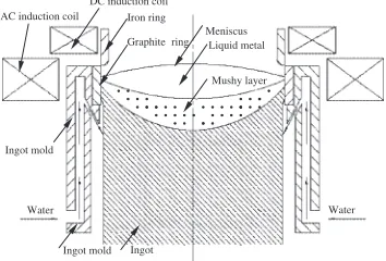
The schematic diagram of LFEVC process is shown in Fig. 1. The ingot mold is made of Al alloy and its center is embedded with a graphite ring. A 60-turn alternate current (AC) induction coil and a 110-turn direct current (DC) induction coil, which are supplied by an alternate electric source and a direct electric source respectively, are laid out around the mold to produce a low-frequency electromagnetic vibrating field.
The aimed alloy (Al-8.5Zn-2.6Mg-2.4Cu-0.13Zr, 7A60) was melted in an induction furnace and further refined at 760C. Then the melt was transferred to the semi-continuous casting machine at 730C and was cast into ingots, which were 270 mm in diameter and 1200 mm in length, with or without a low-frequency electromagnetic vibrating field. During the casting process the pressure intensity of the cooling water was kept constant as 0.01 MPa and the casting velocity was 50 mm/min. The frequency of alternate electro-magnetic field was set as 22 Hz. 4200, 6600 and 9000 At (number of ampere turns) alternate electromagnetic fields
Water
Ingot
Water AC induction coil
Graphite ring
Ingot mold
Meniscus
Mushy layer Liquid metal Iron ring
Ingot mold
DC induction coil
Fig. 1 Schematic diagram of LFEVC process.
[image:1.595.338.515.338.458.2]were matched respectively with 6000, 9900 and 14300 At direct magnetic fields to produce three low-frequency electromagnetic vibrating fields. Their corresponding airy axial magnetic flux intensities on the edge and center of the horizontal symmetric plane of the graphite ring in the mold were measured as shown in Table 1.
After being annealed at 310C for 12 hours, the micro-structures of different positions of the DC and LFEVC ingots were observed by an optical microscope. The chemical compositions (mass. %) of Zn, Mg and Cu, on the cross-section of the ingots were analyzed by inductively coupled plasma (ICP) method to value macro segregation. The concentrations of the alloying elements were measured by electron probe microanalysis (EPMA) by randomly sampling 10 grains or cells at the different areas of the ingots and taking the average. The ratio of the concentration of each element measured by EPMA to the correspondingly macro concentration was calculated and used to evaluate the grain boundary segregation. The ratio was named as local relative concentration (LRC).21)A high LRC value corresponds to a
high concentration inside a grain or cell, i.e., low grain boundary segregation.
Only for a simple comparison, the room temperature hardness at the edge and center of the cross-sections of DC and LFEVC ingots was measured, too. The average hardness was obtained by 6 times measurements by using a Vickers hardness tester with 10 kg load.
3. Results
3.1 Hot-tearing, surface quality and porosity of DC and
LFEVC ingots
During the casting process center-crossing or/and radial hot-tearing are found in almost every DC cast 7A60 alloy ingot, and also found in most of the ingots cast under an weak electromagnetic vibrating field as alternate electromagnetic field is 4200 At, direct magnetic field is 6000 At. At the same time, big cold shuts and slight exudations can be seen from their surfaces. These features are typically shown in Fig. 2(a) and Fig. 3(b). While no hot-tearing and oxide films are observed in stronger LFEVC (alternate electromagnetic field is 9000 At and direct magnetic field is 14300 At) ingots as shown in Fig. 2(b). Figure 3(b) shows its surface. It is obvious that the surface quality is greatly improved under the electromagnetic vibrating field. The macro porosity seen in LFEC (alternate electromagnetic field is 9000 At) ingot is invisible with naked eyes in all DC and LFEVC ingots.
3.2 Microstructures of DC and LFEVC ingots
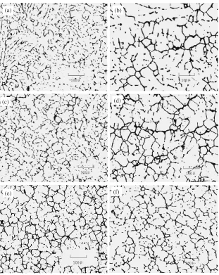
[image:2.595.48.551.84.202.2]From the edge to the center, the microstructures gradually change from finer to coarser in all DC and LFEVC ingots obtained. In general, the microstructures of the LFEVC ingots are much finer compared with the coarse micro-structures of DC ingots. In the latter case, some grains are even visible with naked eyes. Figures 4(a) and (b) are the microstructures taken from the edge and the center of a DC ingot respectively. The microstructures are abnormally coarse and dendritic, and their difference is very notable. When the intensity of the alternate electromagnetic field is weaker than 4200 At and the intensity of the direct magnetic field is weaker than 6000 At, the microstructures both near the edge and at the center of the ingots are still coarse. However, cast under a stronger electromagnetic vibrating field (the alternate electromagnetic field is 6600 At and direct magnetic field is 9000 At), the microstructures near the ingot edge are composed of fine and uniform equiaxed grains as shown in Fig. 4(c). Though the microstructure at the center is much refined, there are still some coarse rosette-shaped grains as shown in Fig. 4(d). Furthermore, when the intensity
Table 1 Axial magnetic flux intensity in the mold.
Axial direct magnetic flux intensity (mT)
Number of ampere turns (At) Alternate field (22 Hz) Direct field
Edge Center Edge Center
4200 26 20
6000 25 19
6600 40 32
9000 52 44
9900 40 31
14300 57 45
Fig. 2 Cross-sections of DC (a) and LFEVC (b) ingots.
[image:2.595.306.548.232.348.2] [image:2.595.306.543.395.487.2]of the alternate electromagnetic field reaches 9000 At and the intensity of the alternate electromagnetic field reaches 14300 At, the microstructures both near the edge and at the center of the ingots become finer, less dendritic or rosette-shaped in feature, as shown in Figs. 4(e) and (f), from which we can see that the ingot is free of oxide films and gas porosity of LFEC ingot with almost the same characteristic microstructures.
3.3 Macro segregation of DC and LFEVC ingots
Figure 5 shows the chemical compositions of Zn, Mg and Cu elements along the radius of DC and LFEVC ingots. DC cast 7A60 alloy ingot presents severe inverse segregations of Zn, Mg and Cu elements as some other traditional Al-Zn-Mg-Cu alloys, 7075 and 7055. When the intensity of the alternate electromagnetic and the direct magnetic field are 4200 At and 6000 At respectively, the macro segregations of Zn, Mg and Cu elements are still very severe. But with the alternate electromagnetic and the direct magnetic field increasing to 6600 At and 9000 At, the macro segregations of Zn, Mg and Cu elements are greatly reduced. With further increasing the intensity of the electromagnetic vibrating field, the macro
segregations of Zn, Mg and Cu elements get their smallest values when the alternate electromagnetic and the direct magnetic field are 9000 At and 14300 At respectively.
3.4 Grain boundary segregation of DC and LFEVC
ingots
The LRCs of the alloying elements Zn, Mg and Cu at the center of DC and LFEVC ingots are shown in Fig. 6. From Fig. 6, the LRCs of Zn, Mg and Cu are remarkably increased under the influence of the electromagnetic vibrating field, from 45.6, 47.8 and 30.1% respectively in DC ingot to 71.1, 75.8 and 44.5% respectively in LFEVC ingot. The stronger the electromagnetic vibrating field is, the higher the concen-tration of alloying elements within grains. At weak electro-magnetic vibrating field (the alternate electroelectro-magnetic and the direct magnetic field are 4200 At and 6000 At respec-tively), the LRCs of Zn, Mg and Cu within grains are 46.5, 48.9 and 31.2%, respectively, which are almost equal to those of the DC ingot. When the number of ampere turns of the alternate electromagnetic and the direct magnetic field increase to 6600 At and 9000 At, the LRCs increase rapidly. While the number of ampere turns of the alternate
electro-(a) (b)
(f)
(c) (d)
(e)
[image:3.595.143.454.70.461.2]magnetic and the direct magnetic field further increase to 9000 At and 14300 At, the LRCs increase more rapidly and reaches to their maximum values,i.e., 71.1, 75.8 and 44.5% respectively.
3.5 Vickers hardness of DC and LFEVC ingots
Similarly, the Vickers hardness increases with the increase of the intensity of the electromagnetic vibrating field as shown in Fig. 7. The DC cast ingot represents lower Vickers hardness values, 60.9 and 46.2, both at its edge and center. At the weaker electromagnetic vibrating field (the alternate electromagnetic and the direct magnetic field are 4200 At and 6000 At respectively), the edge hardness is slightly higher than the one of DC ingot, while the center one is almost equal to the one of DC ingot. With increasing the intensity electromagnetic vibrating field from 4200 At and 6000 At of the alternate electromagnetic and the direct magnetic field to 6600 At (AC electromagnetic filed) and 9000 At (DC magnetic filed), then to 9000 At (AC electromagnetic filed) and 14300 At (DC magnetic filed), the edge hardness first increase quickly then slowly, while the center hardness first increase slowly then quickly, then the hardness reach to their maximum values,i.e., 84.2 and 74.9 respectively.
4. Discussion
A time varying magnetic field BðtÞ and a stationary magnetic filedB0are generated in the melt by imposing an
alternate current and a direct current into the two induction coils respectively as shown in Fig. 1. An important param-eter, skin depth, which denotes to the effective distance
0 20 40 60 80 100 120 140
7.4 7.6 7.8 8.0 8.2 8.4 8.6 8.8
Mg concentration, (%)
Distance from chill, d/mm AC:9000At,DC:14300At AC:6600At,DC:9900At AC:4200At,DC:6000At DC casting
0 20 40 60 80 100 120 140
1.6 1.8 2.0 2.2 2.4
Mg concentration, (%)
Distance from chill, d/mm AC:9000At,DC:14300At AC:6600At,DC:9900At AC:4200At,DC:6000At DC casting
0 20 40 60 80 100 120 140
1.6 1.8 2.0 2.2 2.4 2.6 2.8 3.0
Mg concentration, (%)
Distance from chill, d/mm AC:9000At,DC:14300At AC:6600At,DC:9900At AC:4200At,DC:6000At DC casting
(a) (b)
(c)
0 10 20 30 40 50 60 70 80 90 100
DC casting AC:4200At,DC:6000At AC:6600At,DC:9900At AC:9000At,DC:14300At
Zn Mg Cu
LRC, (%)
Fig. 6 LRCs of Zn, Mg and Cu of DC and LFEVC ingots.
0 10 20 30 40 50 60 70 80
90 DC casting
AC:4200At,DC:6000At AC:6600At,DC:9900At AC:9000At,DC:14300At
Hardness, (Hv)
Edge Center
Fig. 7 Vickers hardness of DC and LFEVC ingots.
[image:4.595.94.505.75.401.2] [image:4.595.70.269.621.765.2]where a time varying magnetic field transfers into the melt and decays to 1/e (about 37%) of its value, can be expressed as:
¼
ffiffiffiffiffiffiffiffiffiffiffi 1
uf
s
ð1Þ
where , u and f are the conductivity, permeability of the melt and the frequency respectively. Clearly, adopting lower frequency means higher alternate electromagnetic intensity deeply into the central melt at an identical ampere turns of the induction coil.21)
The time varying magnetic field BðtÞ gives rise to an induced currentJin melt and/or ingot. Therefore, the melt is subjected to electromagnetic body forces caused by the interaction of the magnetic field and its induced current. The time-dependent electromagnetic force density consists of two parts expressed as follows:
F1¼JB¼
1
uðB rÞB
1
2urB
2 ð2Þ
The two terms on the right hand of eq. (2) are a rotational forceF2and a potential forceF3, respectively. The principle
of electromagnetic vibration has been analyzed by Vives23)as shown in Fig. 8. The magnetic fields,B0andBðtÞ, are nearly
patrolled to the vertical axis of the ingot. The combined action of the collinear fields generates vibrations in the melt, which are of dual origins: the interaction of B0 and J
engenders a vibrating force F4¼JB0 of frequency f,
synchronously the force F1 consists of a time-independent
component F5 and a vibrating component F6 of 2f. The
intensity of the electromagnetic vibration depends on the intensities of local B0 and/or B. The cast-ability and
solidifying process of 7A60 alloy will be influenced mainly by the interaction of the electromagnetic forces.
The potential electromagnetic force F3 is balanced by
static pressure of the melt, resulting in the formation of a convex surface (meniscus) and a decrease in the contacting pressure on the mold (soft contact), thus result in good surface as shown in Fig. 3 in a suitable intensity.
In general, a nucleus growth process can be divided into three phases: global growth, dendritic growth and ripened rosette. More nuclei imply a finer microstructure of the
ingots. From the micro view, when these above-mentioned electromagnetic vibrating forces,F4and/orF6are imposed
on the melt, a lot of micro melt units are subject to a compressed stress, thus some atom clusters may form in this area because of high pressure. We speculate that during the nucleation process the atom clusters could easily attach to the potential substratum (ZrAl3, MnAl6, FeAl3 and so on) and
mold wall to reduce the energy barrier for nucleation, therefore leading to the increased amount of nuclei. From the macro view, the forced convection generated by the rota-tional electromagnetic forceF2results in a flow of the cooler
melt from the edge of the mold to the center and vice versa, which establishes a more uniform flow, temperature, and solute field. The merits of the uniform temperature field for fine microstructures can be divided into two folds: on one hand, the melt can be undercooled and nucleation can take place almost simultaneously in the mold resulting in an enlarged mushy zone. The subsequent result of it is that the microstructure, especially central microstructure of LFEVC ingots is fine and uniform. On the other hand, more nucleation will take place on the mold wall in a thin layer of deeply undercooled melt, under the vibrating force and forced convection, the nuclei are separated easily from the mold wall and taken into the melt center continuously as some other substrates, some new nuclei form in the melt. However, for LFEC without electromagnetic vibration (F4),
fine microstructures at the center of the ingots need further increasing alterative electromagnetic intensity, but over drastic fluctuation leads to breakage of oxide film, thus results in internal oxide film and gas porosity.
More uniform solidifying temperature means lower hot-tearing tendency because of lower solidifying stress, and more uniform solute leads to lower macro segregation. In addition, fine macrostructures, especially global or net-global grains, are suitable for transportation of the liquid, especially during the period of high-fraction solid, thus reduce the micro interdendritic porosity because of solidification shrinkage, and increases the ability to restrain hot-tearing due to fine grains, further contribute to the hot-tearing-free ingots and weaker macro segregation, as shown in Figs. 2 and 5.
The alloy melt is considered as a system consisting of atomic nuclei surrounded by negatively charged electrons. The relative movement of Al3þ, Cuþ, Mg2þand Zn2þ, which is produced by electromagnetic field, promotes the entropy of the melt in front of the solid-liquid interface, and in order to reduce free energy the solute elements automatically scatter throughout the melt.21) The increased number of nuclei
decrease the distance that solute elements need to travel, the concentration of solute elements along grain boundaries is low. Both of the two reasons lead to an increase of the content of alloying elements within grains and reduce the grain boundary segregation. Stronger electromagnetic vibration means higher amplitude of vector sum of the alternate and direct magnetic flux intensities, thus the relative movement is more drastic.
In the case of a stable low frequency, 22 Hz in this study, increasing the alternate electromagnetic field and direct magnetic field are helpful to improve surface, resist hot-tearing, refine macrostructures, and suppress macro segrega-tion and grain boundary segregasegrega-tion, as shown in Figs. 2, 3,
Z
B
0B(t)
M
M’
M”
O
J
F
U
[image:5.595.78.256.615.766.2]4, 5 and 6. Certainly, the higher as-cast Vickers hardness are related to finer structure and higher content of alloying elements within grains, as shown in Fig. 7.
5. Conclusion
With increasing alternate and direct current ampere turns, LFEVC can significantly improve surface quality, decrease hot-tearing tendency, generate much finer, more uniform and equiaxed microstructures, and greatly suppress macro segre-gation and grain boundary segresegre-gation of DC ingots. When the frequency and number of ampere turns of alternate electromagnetic field are 22 Hz and 9000 At, and the number of ampere turns of direct magnetic field is 14300 At, the ingot has smoothest surface, lowest macro segregation, and very fine, uniform and equiaxed microstructures, and is also free of hot-tearing, oxide films and gas porosity. Its LRCs of Zn, Mg and Cu (68.8, 76 and 45%) and Vickers hardness (84.2 and 74.9 respectively at edge and center of the ingot) are the highest.
Acknowledgements
The National Natural Science Foundation of China (Grants No. 2001AA332030) is greatly acknowledged for their financial support.
REFERENCES
1) T. M. Osman, P. M. Singh and J. J. Lewandowski: Scr. Metall. Mater.
31(1994) 607–612.
2) A. B. Pandey, B. S. Majumdar and D. B. Miracle: Metall. Mater. Trans.
A29(1998) 1237–1243.
3) H. Adachi, K. Osamura, S. Ochiai, J. Kusui and K. Yokoe: Scr. Mater.
44(2001) 1489–1492.
4) C. G. Li, S. J. Wu, S. L. Dai and S. J. Yang: The Chinese journal of nonferrous metals (Special).12(2002) 14–21.
5) C. Q. Chen: The Chinese journal of nonferrous metals (Special).12
(2002) 22–27.
6) Y. L. Wu, F. H. Froes, A. Alvarez, C. G. Li and J. Liu: Materials & Design.18(1997) 211–215.
7) J. Kusui, K. Fujii, K. Yokoe, T. Yokote, K. Osamura, O. Kubota and H. Okuda: Mater. Sci. Forum.217(1996) 217–222.
8) Q. Wei, B. Q. Xiong, Y. A. Zhang, B. H. Zhu and L. K. Shi: Transactions of Nonferrous Metals Society of China (English Edition).
11(2001) 258–261.
9) S. Asai: Sci. Technol. Adv. Mater.1(2000) 191–200.
10) G. I. Eskin, G. S. Makarov and Pimenov and Yu P: Adv. Performance Mater.21(1995) 43–50.
11) C. Vives: Metall. Trans. BB20(1989) 623–629. 12) C. Vives: Metall. Mater. Trans. BB7(1996) 457–464.
13) P. Desnian, F. Durand, Y. Fautrelle, D. Bloch, J. l. Meyer and J. P. Riquet: Light Metals TMS. (1988) 487–93.
14) A. Radjia and K. Miwa: Metall. Mater. Trans. AA31(2000) 755–62. 15) S.-C. Lim, E.-p. Yon and J.-S. Kim: J. Mater. Sci. Lett.16(1997)
104–09.
16) C. Vives: Metall. Mater. Trans. BB27(1996) 445–55. 17) C. Vives: Metall. Mater. Trans. BB27(1996) 457–64.
18) C. J. Paradies, R. N. Smith and M. E. Glichsman: Metall. Mater. Trans. AA28(1997) 875–83.
19) J. Pilling and A. Hellawell: Metall. Mater. Trans. A A27 (1996) 239–32.
20) B. J. Zhang, J. Z. Cui, G. M. Lu, Q. Zhang and C. Y. Ban: Acta Metall. Sinica38(2002) 215–219.
21) J. Dong, J. Z. Cui, F. X. Yu, C. Y. Ban and Z. H. Zhao: Metall. Mater. Trans AA35(2004) 2487–2494.