Limit Load Analysis of Pressure Structures Containing Pitting Defects Subjected
to High Temperature Creep
Ning Wang
*1and Hong-qi Liu
*2Key Laboratory of Pressure System and Safety, Ministry of Education, East China University of Science and Technology, Shanghai 200237, China
High-temperature technologies are widely used in many industries and the high temperature components are usually designed for long term operation. Creep damages are inevitable in service, which may lead to the loss of material strength. Volumetric defects such as pits may occur during the manufacturing process and during service. These defects may cause severe reduction of the limit load of structures. The exist-ing assessment procedures do not take into account the effect of plasticity-damage due to creep, which may lead to inaccurate assessment results. This paper aims to investigate the limit load of pressurized components with volumetric defect subjected to high temperature creep. An elas-to-plastic constitutive model with coupled plasticity-damage due to creep effects is proposed. The limit load of high temperature structures with volumetric defects is systematically studied using finite element method. Safety assessment approach for structures considering plasticity-dam-age due to creep effect is subsequently proposed based on the principle of fitness for service . [doi:10.2320/matertrans.M2015393]
(Received October 22, 2015; Accepted January 12, 2016; Published March 25, 2016)
Keywords: high temperature creep, plasticity-damage due to creep, pitting defect, limit load, safety assessment
1. Introduction
The in service temperatures and loading conditions for high temperature components are becoming increasingly more complicated, which makes efficiency, energy conserva-tion and environmental protecconserva-tion a great concern in the chemical industries. Moreover, considerable in-service power and chemical plants are operated beyond the designed life for economical reason. Under these circumstances, accurate pre-diction of the limit load of high temperature components stand out in the process of assessment, inspection and main-tenance.
Such structured materials are widely believed to have their mechanical properties connected to their defects in structures. Cracks in metals at elevated temperature had received much attention1), some of the researchers have derived laws of creep crack growth and its life for these materials by conduct-ing creep crack growth2–4) and multiscale studies5). While volumetric defects such as pits are known to be another com-mon defects for pressure equipment in the process of manu-facture, installation and operation, due to mechanical damage or erosion-corrosion. This in turn causes the local stress con-centration and reduce the limit load of the structure, poten-tially causing failure or disasters. Many studies have been carried out to deal with these problems. Kitching6) computed a lower bound to the limit pressure of a cylindrical shell with a rectangular slot part through the thickness at mid-length us-ing a linear optimization technique. Miller7) reviewed exist-ing limit loads of structures containexist-ing defects includexist-ing the empirical equations and analytical solutions. But limited to computation conditions at that time, many rules were based on assumptions and simplified. Chen et al.8) formulated the 3-D limit analysis of rigid-perfectly plastic structures as a dis-crete nonlinear mathematical programming problem with only equality constraints by means of the finite element tech-nique. The influence of defects shape and size on the
struc-ture limit load were studied and formula were fitted for safety assessment of the structure containing pitting defects9).
However, these studies were based on elastic-perfectly plastic material and did not take the effect of high tempera-ture plasticity-damage due to creep into account. Creep is one of the most important factors for degradation of material properties at high temperature.
Research on design and prediction of remaining strength of thin/thick walled cylinders under creep condition has been discussed10–12). Theoretical derivation and experimental pro-cedures are covered as well as numerical analysis, including the determination of plastic loads pipes with internal fluid pressure. During the life of the component, the rate constantly varies due to time-dependency of stresses and variation in stresses through the tube wall thickness13). Kachanov and Rabotnov14,15) opened a new era of study on creep damage by establishing a constitutive model to describe the rule of creep damage evolution based on damage factor. Recently research-ers built more damage models based on microstructural mechanism. Preußner et al.16) developed a creep model based on the dislocation density and studied creep behavior of met-als with fcc, bcc and hcp crystal structures. Fischer and Svo-boda17) extended the diffusion creep model to general dislo-cation structure.
Despite the substantial literature mentioned above, these efforts have failed to describe the loss of material strength due to plasticity-damage due to creep. Therefore this paper aims to establish a coupled elasto-plastic plasticity-damage due to creep constitutive model. This proposed model will be em-ployed to predict the elasto-plastic response of long-term op-erational materials under high temperature. The limit load of high temperature structures with volumetric defects is sys-tematically studied using finite element method. Safety as-sessment approach for structures considering plasticity-dam-age due to creep effect is subsequently proposed based on the principle of fitness for service .
*1
Corresponding author: E-mail: [email protected]
*2
2. Plasticity-Damage due to Creep Evolution
Plasticity-damage due to creep is affected by the following three factors from the microstructure; (i) the particle coarsen-ing, (ii) and solid solution depleted and (iii) micro-cavity nu-cleation. Therefore the damage evolution model can be estab-lished by incorporating these factors.
Damage rate due to particle coarsening D˙P 18) is given by
˙
DP= KP(1−DP) 4
3 , DP(t0)=0, DP(tr)=1 (1) In the equation, t0, tr is the start and rupture time of creep.
KP is rate constant for particle coarsening.
Damage rate due to precipitated particles D˙S 18) is given by ˙
DS=KSDS1/3(1−DS), DS(t0)=0, DS(tr)=1 (2)
where KS is rate constant for precipitated particles.
During the late stage of creep, voids and micro-cracks exert a growing influence in the plasticity-damage due to creep evolution. The dominant factor of damage evolution would be the void nucleating and growth, the number density of voids is a stable value in the process of damage evolution.
Damage rate due to cavitations D˙N 18) is given by
˙
DN= Aσ υ
(1−DN)ϕ, DN(t0)=0, DN(tr)=1 (3) Where, A, υ, φ are constants related to the minimum creep rate.
From the analysis above, plasticity-damage due to creep is not caused by a single isolated mechanism of material degra-dation, but as a result from a combination of multiple factors. The total plasticity-damage due to creep D can therefore be expressed as19)
D=1−(1−DP)(1−DS)(1−DN) (4)
Where, the DP, DS, DN can be determined by solving dif-ferential eqs. (1), (2) and (3).
2.1 Coupled plasticity-damage due to creep constitutive model
There are various elasto-plastic constitutive models, such as perfect elasto-plastic model, linear hardening model and power law model etc. Considering that the yield platform of material in this study is short, similar to the Ramberg-Osgood model, this model is thus chosen to describe the elasto-plastic response of material plasticity-damage due to creep.
The Ramberg-Osgood model was proposed in 1943, and the stress-strain relation is defined by
ε=σ
E +α
σ σp
n
(5)
where E is the elastic modulus, σ is the stress, σp is the refer-ence stress, n is the strain-hardening exponent and α is the offset of yield.
Damage was presented originally as an engineering con-cept and there are various definitions from different research-ers. Based on the classic continuum mechanics, continuum damage mechanics (CDM) introduced an internal variable which can describe the internal defects inside the materials, and estimate the creep damage to obtain the mechanical
prop-erties of damaged materials20).
According to the conventional creep-damage theory of Kachanov-Rabotnov, the constitutive and the evolution equa-tion in uniaxial stress are given as follows21,22)
dε dt =A
σ 1−D
n
(6)
dD dt =H
σ 1−D
q
(7)
Where, ε, σ, D are the creep strain, tensile stress and damage variable and A, n, H, q are the material constants.
Based on the studies of Ashby and Dyson23), plastici-ty-damage due to creep models under different mechanisms can be expressed by eq. (6) and eq. (7). In this research, the authors have developed a continuum damage model by sub-stituting eq. (4) into Ramberg-Osgood model, then the cou-pled plasticity-damage due to creep constitutive can be ex-pressed as follow:
ε= σ
E(1−D)+α σ (1−D)σp
n
(8)
2.2 Validation of constitutive model
The material constants α and n in eq. (8) can be determined by uniaxial tensile curves under different strain rates. The damage factor D in eq. (8) is calculated by DP, DS, DN from eq. (1), (2) and (3), where the parameter KP and KS in eq. (1) and (2) are obtained from literature24) and the D
N in eq. (3) can be determined by the creep parameters E, A, υ, ϕ of 2.25Cr1Mo steel at 550 C (the specific parameters in Table 1, where the stress unit is MPa, and time unit is hour).
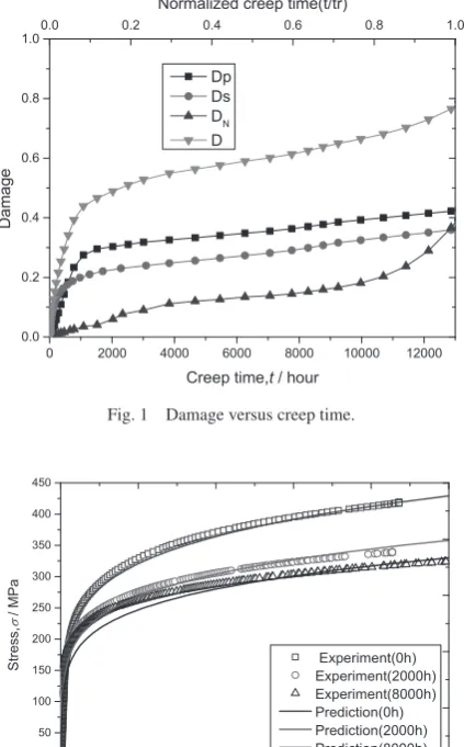
The plasticity-damage due to creep DP, DS, DN for a given creep time can be obtained by numerical integration of the eq. (1)~(3). For the test condition 550 C, 120 MPa, the creep rupture life of 13,000 hours, and DP, DS, DN are achieved by numerically integrating the eq. (1)~(3), then the total damage D is calculated by eq. (4) (see Fig. 1). The damage levels for 2000 h and 8000 h are then calculated as 0.487 and 0.566 re-spectively.
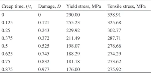
The material stress-strain relationship at this time can be obtained by substituting D into the eq. (8). In order to validate the model we need the materials with different level of creep damage. It was difficult to obtain the longtime creep damage material, so it was decided to accelerated creep testing in lab-oratory. Specimens have been creep tested at 550 C, 9.8 MPa. In each case, the tests were interrupted at different stage. The stress-strain curves calculated by the model are compared with the experimental data in Fig. 2. It can be seen that the calculated result agrees quite well with the experiment output and predicts the true stress-strain relationship of the creep material. To further verifying the accuracy of the proposed model, predictions are made with data from the literature24–27), which are the yield and tensile stresses of 2.25Cr1Mo steel
Table 1 Material parameters of 2.25Cr1Mo steel at 550°C.
E (MPa) A υ φ α n KP KS
after creep for different long term temperatures at 550 C, 9.8 MPa being used. Although the experimental data is taken from different literature, the error between model prediction and experimental data is no more than 8%. As is shown in Fig. 3, the model prediction is in accordance with the litera-ture data.
3. Limit Load Analysis of High Temperature Pressur-ized Components with Volumetric Defects
This paper deals with the pressure structures containing volumetric defect, the geometric model of cylindrical struc-ture under inner pressure load is shown in Fig. 4. Due to the rotational symmetry, only one-quarter of the total geometry was modelled. Three-dimensional eight-node solid elements with reduced integration (element C3D8R in ABAQUS) were employed to model the structures containing the spherical and ellipsoidal pits (Fig. 5). Approximately 5400 elements were utilized in each structure. For verifying the finite ele-ment study and testing the convergence, we performed three additional finite element studies were performed and the number of elements (4000 & 9000 elements) was varied. There were only small differences in the strain and stress val-ues between the 9000 and 5000 eight-node study.
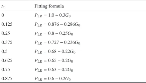
According to the constitutive presented this paper, me-chanical properties of materials for the 2.25Cr1Mo steel with different plasticity-damage due to creep are calculated in Ta-ble 2.
Conventional limit analysis assumes that the structure of the ideal elastic-plastic material can withstand maximum load. Considering the potential of strengthening of materials, the true stress-strain was introduced in modelling. The mate-rial load - displacement curve was drawn with the incremen-tal finite element method and then the limit loads were deter-mined according to the zero curvature method.
To simplify the defect, we define K = Ro/Ri, A/B, C/B, C/T represent the ratio of defect. Limit load is normalized as PLS =
PL/PL0, here PL0 is the limit load of the structure without de-fect. Considering the materials with different creep duration, the plasticity-damage due to creep is defined as normalized creep time tC = t/tr, here t is creep time and tr is the creep rupture time. In this paper, two types of pit defect on the out-er of thick wall cylindout-er (K = 1.25) was studied, the sphout-erical and ellipsoid, the value of the parameters are shown in Ta-ble 3.
Using the FE model and parameters above, the limit load solutions of cylinder including pit defect and different plas-ticity-damage due to creep on the internal pressure are solved. Based on the analysis, different effects such as defects and plasticity-damage due to creep on the limit loads are plotted in Figs. 6–9.
From Figs. 6–9 we can see that the limit load of cylinder will decrease linearly with an increase in size of defect and Fig. 1 Damage versus creep time.
Fig. 2 Stress-strain curves of different creep damage materials.
Fig. 3 Tensile properties of test materials in comparison with literature
[image:3.595.63.275.188.529.2] [image:3.595.63.274.602.761.2] [image:3.595.303.548.647.772.2]nonlinearly with increase inthe creep time. According to Ta-ble 3, under the same condition of C/B, the limit load of cyl-inder will decrease with A/B increasing. Results indicate that
the cylinder with ellipsoidal pit defect (A/B = 5) has a lower
limit load than that with spherical pit defect (A/B = 1) if the size of defect is equivalent. The limit load of cylinder de-creases sharply in the early stages of the plasticity-damage due to creep, with subsequent gradual slow down. The cylin-der with ellipsoidal pit defect (A/B = 5) is more susceptible to
plasticity-damage due to creep than that with spherical pit defect (A/B = 1).
Table 2 Mechanical properties of 2.25Cr1Mo steel with different creep damage.
Creep time, t/tr Damage, D Yield stress, MPa Tensile stress, MPa
0 0 290.00 358.91
0.125 0.121 255.23 325.68
0.25 0.243 229.92 302.77
0.375 0.372 211.49 287.71
0.5 0.525 198.07 278.66
0.625 0.745 188.29 274.29
0.75 0.832 181.18 273.62
0.875 0.977 176.00 275.92
Table 3 Value of the parameters in computation model.
Parameter Value
A/B 1,3,5
C/B 1,0.33,0.25
C/T 0.33,0.5,0.6
tC 0,0.125,0.25,0.375,0.5,0.625,0.75,0.875 Fig. 6 The effect of spherical pit defect (A/B = 1) depth on limit load, (a) C/B = 1; (b) C/B = 0.33.
Fig. 5 Typical finite element mesh of the models a) spherical pit; b) ellipsoidal pit.
[image:4.595.120.479.57.177.2] [image:4.595.121.476.226.363.2] [image:4.595.112.490.402.534.2] [image:4.595.305.554.597.666.2] [image:4.595.47.291.607.726.2]4. Limit Load Assessment of High Temperature Pres-surized Components with Volumetric Defects
Let g0 as a dimensionless parameter
g0=CT ·AB·RB m ·
Rm T
1 2
=C
T · A
√R
mT
(9)
Where, A, B, C are sizes of defect, Rm and T are diameter and wall thickness respectively. According the literature28), the limit load of cylinder with a pit outside is more sensitive to the square root of g0. Therefore let,
G0= √g0 (10)
By fitting the data in the Figs. 6–9, then the Limit loads of the cylinder with pit outside varying with defect dimension and plasticity-damages due to creep can be calculated, as shown in Fig. 10 and Table 4.
Fig. 10 Limit loads of the cylinder with pit outside varying with defect dimension and creep damages, (a) 3D coordinate relation; (b) Fitting curves.
Table 4 Fitting formula of limit loads and defect dimension with different creep damages.
tC Fitting formula
0 PLR=1.0−0.3G0
0.125 PLR=0.876−0.286G0
0.25 PLR=0.8−0.25G0
0.375 PLR=0.727−0.236G0
0.5 PLR=0.68−0.22G0
0.625 PLR=0.65−0.2G0
0.75 PLR=0.63−0.2G0
0.875 PLR=0.6−0.2G0
[image:5.595.116.479.72.200.2] [image:5.595.115.481.238.367.2] [image:5.595.115.485.405.534.2] [image:5.595.47.290.607.746.2]According to Table 4, at a conservative estimate of the lim-it load of the cylinder wlim-ith defect and different plastici-ty-damages due to creep subjected to internal pressure load is
PLR
C=e−tC−0.3G
0 tC≤0.5
PLRC=e−tC−0.2G0 tC>0.5 (11)
5. Conclusion
Considering the microstructure mechanism of plastici-ty-damage due to creep, an elasto-plastic constitute is estab-lished by coupling the plasticity-damage due to creep into Ramberg-Osgood model. The main conclusions are summa-rized below.
Based on the creep and tensile experiments and CDM plas-ticity-damage due to creep model, an elasto-plastic constitu-tive relation was established. The proposed model is able to offer helpful and reliable predictions of the effect of lastici-ty-damage due to creep of materials.
The limit load of high temperature structures with volu-metric defects is systematically studied using finite element method. The cylinder with ellipsoidal pit defect has a lower limit load than that with spherical pit defect when the size of defect is equivalent. And it is more susceptible to plastici-ty-damage due to creep than that with spherical pit defect.
Safety assessment approach for structures considering plasticity-damage due to creep effect is subsequently pro-posed based on the principle of fitness for service .
Acknowledgements
The authors gratefully acknowledge the financial support-ed by the Projects of the National Natural Science Foundation of China (51405159) and the Natural Science Foundation of Shanghai (14ZR1410900).
REFERENCES
1) A. T. Yokobori Jr.: Mater. High Temp. 28 (2011) 126–136.
2) R. Sugiura, A. T. Yokobori Jr., S. Takamori, M. Tabuchi, A. Fuji, M. Yoda, K. Kobayashi and T. Yokobori: Mater. Trans. 48 (2007) 2928– 2936.
3) H. Naoi: Nippon Steel Technical Report 347 (1992) 27–31. 4) F. Abe and S. Nakazawa: Metall. Trans. A 23 (1992) 3025–3034. 5) A. T. Yokobori Jr., R. Sugiura, T. Ohmi and R. A. Ainsworth: Strength,
Fract. Complex. 8 (2014) 205–218.
6) R. Kitching and K. Zarrabi: Int. J. Mech. Sci. 23 (1981) 31–48. 7) A. G. Miller: Int. J. Press. Vess. Pip. 32 (1988) 197–327.
8) G. Chen: Diss. Ph. D. Thesis, Tsinghua University, Beijing, China, (1994).
9) Y. H. Liu, Z. Z. Cen and B. Y. Xu: Int. J. Solid Struct. 32 (1995) 1645– 1658.
10) R. Viswanathan, S. R. Paterson, H. Grunloh and S. Gehl: J. Press. Vess. Technol. Asme 116 (1994) 1–16.
11) D. R. H. Jones: Eng. Fail. Anal. 11 (2004) 873–893.
12) J. Jelwan, M. Chowdhury and G. Pearce: Eng. Fail. Anal. 27 (2013) 350–372.
13) A. Loghman and M. A. Wahab: Int. J. Press. Vess. Pip. 67 (1996) 105– 111.
14) L. M. Kachanov: Izv. Akad. Nauk. SSR. Otd Tekh. Nauk 8 (1958) 26– 31.
15) Y. N. Rabotnov: Proc. ICAM-12, (1968) pp. 342–349.
16) J. Preußner, Y. Rudnik, H. Brehm, R. Völkl and U. Glatzel: Int. J. Plas-ticity 25 (2009) 973–994.
17) F. D. Fischer and J. Svoboda: Int. J. Plasticity 27 (2011) 1384–1390. 18) B. Dyson: J Press Vess-T Asme 122 (2000) 281–296.
19) M. Basirat, T. Shrestha, G. P. Potirniche, I. Charit and K. Rink: Int. J. Plasticity 37 (2012) 95–107.
20) Y. Liu: Diss. Ph. D. thesis, Southwestern Jiaotong University, Chengdu, China, (1990).
21) H. Kraus: Creep Analysis, New York (John Wiley & Sons, Inc. 1980). 22) J. T. Boyle and J. Spence: Stress Analysis for Creep, Southampton,
(Butterworths & The Camelot Press Ltd., 1983).
23) M. F. Ashby and B. F. Dyson: Plasticity-damage due to creep Mechan-ics and MicromechanMechan-ics, Proceedings of ICF-6, (1984).
24) B. X. Si, Z. Y. Lin, et al: Zhejiang Electric Power 2 (2007) 55–58 (in Chinese).
25) H. S. Shen, Y. B. Chen, et al: East China Electric Power 12 (1993) 4–8 (in Chinese).
26) Y. X. Jin: Phys. Test. Chem. Anal. Part A: Phys. Test. 2 (1993) 38–40 (in Chinese).
27) L. Y. Dong and C. J. Liu: Press. Vess. Technol. 22 (2005) 45–48 (in Chinese).
28) GB/T2039-1997 Metallic materials Creep and stress rupture test in ten-sion[S] (in Chinese).
Nomenclature
˙
DP Damage rate due to particle coarsening DP Damage due to particle coarsening
KP Rate constant for particle coarsening
t0 Start time of creep
tr Rupture time of creep
˙
DS Damage rate due to precipitated particles DS Damage due to precipitated particles
KS Rate constant for precipitated particles ˙
DN Damage rate due to cavitation
DN Damage due to cavitation
D Total plasticity-damage due to creep
σ Stress
ε Strain
E Elastic modulus
σp Reference stress
A, n, H, q, υ, φ, α Material constants
Ri, Ro, Rm Inner, outer and medium diameter of the cylinder
T Wall thickness of the cylinder
A/B, C/B, C/T Ratio of defect size
g0, G0 Dimensionless parameter
PL Limit load of the structure
PL0 Limit load of the structure without defect
PLS Normalized limit load
tC Normalized creep time
PC