Enhancement of Fatigue Life in TiNi Shape Memory Alloy
by Ultrasonic Shot Peening
Kohei Takeda
1,+, Ryosuke Matsui
1, Hisaaki Tobushi
1, Shinichi Homma
2and Kanehisa Hattori
3 1Department of Mechanical Engineering, Aichi Institute of Technology, Toyota 470-0392, Japan2Nippon Trex Co., Ltd., Toyokawa 441-0193, Japan
3Toyo Seiko Co., Ltd., Yatomi 490-1412, Japan
The fatigue property of shape memory alloy (SMA) is one of the most important subjects in view of evaluating functional characteristics of SMA elements. In the present study, ultrasonic shot peening (USP) was applied to induce compressive residual stress on the surface layer of TiNi SMA tape and the influence of USP on the bending fatigue life was investigated. The fatigue life of USP-treated tape is longer than that of the as-received tape. The fatigue life of the tape treated with high coverage is longer than that with low coverage. The fatigue life of the USP-treated tape increases in proportion to the hardness on the surface of the tape. [doi:10.2320/matertrans.MBW201408]
(Received October 20, 2014; Accepted January 29, 2015; Published March 6, 2015)
Keywords: shape memory alloy, titanium-nickel alloy, superelasticity, ultrasonic shot peening, fatigue, bending
1. Introduction
The shape memory alloy (SMA) is expected to be applied as intelligent material since it shows the unique character-istics of the shape memory effect and superelasticity.1) The TiNi SMAs are among the best SMAs since the fatigue life is longer, the recoverable strain is larger and the corrosion resistance is higher than other SMAs. With respect to the fatigue properties, the fatigue tests in tension and rotating bending have been conducted.24) However, the
plane-bending deformation is used in practical applications. In the growing number of TiNi SMA applications, these materials should fulfill high requirements of fatigue, corrosion and wear resistance. On the other hand, the application of SMA has some limitations, particularly in thermomechanical cyclic loading cases. If the maximum strain is large, mechanical property can change during cycling and structural compo-nents can be damaged due to fatigue under high cycles.5,6)In these cases, fatigue of SMA is one of the important properties in view of evaluating functional characteristics as SMA elements.
It is known that the shot peening is used to induce compressive residual stresses on the surface layer of metallic parts.7) The residual stresses produced increase the fatigue
performances. The ultrasonic shot peening (USP) has the following advantages: (1) saving space since cabinet and dust collector are not needed, (2) clean operation lines with improved operation environment (dust and noise) because of no dust collector used in lines and (3) shot peening effect with the same or higher compressive residual stress compared to conventional shot peening and with the better surface finishing than conventional shot peening.8) It is suggested
that USP would produce SMA elements with a longer working life. The study on enhancement of the fatigue life for TiNi SMA by USP has not been investigated till now. In particular, since impressions appear little by USP in the region of superelasticity, the influence of USP on the fatigue life is not clear.
In this paper, we report and discuss the influence of USP shot media diameter and coverage on the bending fatigue life of TiNi SMA tape which shows superelasticity.
2. Experimental Procedure
The materials used in the experiment were Ti-50.85 at%Ni tapes with a thickness of 1 mm and a width of 2.5 mm. The length of the tapes was 80 mm for the tension test and 100 mm for the fatigue test. They were polycrystalline, produced by Furukawa Techno Material Co., Ltd. and applied to an element of a brassiere. The tapes were heat-treated at 803 K for 10 min in air followed by water quench. The material shows superelasticity at room temperature.
In order to investigate the influence of USP on the fatigue life, the tapes were USP-treated. In order to investigate the influence of surface roughness on the fatigue life, the surface of the tape in one group was polished by using the abrasive paper No 1000, 1200, 1500, 2000, 2500 and then finished using 0.04 micron SiO2 colloidal suspension.
The specimen were divided into the following groups: (1) as-received, (2) polished and (3) three kinds of USP-treated tapes.
One end of a TiNi SMA tape was gripped during USP treatment. Both flat surfaces of the tape were shot-peened from two opposite directions by steel balls as shot media. The shot media was an SUJ2 steel ball with Vickers hardnessHV
of 850 used for a miniature bearing. Diameters of the steel balls used were 0.8 mm and 1.2 mm. USP was carried out using the ultrasonic equipment produced by SONATS (Toyo Seiko Co., Ltd.). The frequency of the vibrating sonotrode was 20 kHz. The impressions do not clearly appear on the shot-peened surface of the superelastic SMA. In order to specify the peening intensity of USP, Almen test strips were used. The coverage was obtained as follows: (1) the time of the USP-treatment for Almen test strips to the coverage of 100%was measured atfirst, and (2), in the case of coverage of 2000%, the USP-treatment was applied to the SMA tape for 20 times longer time than that of the coverage of 100%. Coverages applied were 2000% and 4000%. In the test to
+Corresponding author, E-mail: k-takeda@aitech.ac.jp
machine9) was used. The test for alternating-plane bending
fatigue was carried out in air at room temperature. The maximum bending strain appeared on the flat surface of the SMA tape at which USP was applied. The frequency of cyclic bending was found to be 2.5 Hz (150 cpm). Temper-ature of the specimen surface at the midpoint of two grips, where the maximum bending strain appeared, was measured by a thermocouple during the alternating-plane bending fatigue test.
A scanning electron microscope (SEM) was used to observe the fracture surface of the specimen.
A laser microscope VK-X200 made by Keyence Co. was used to observe the surface roughness of the specimen.
The Vickers hardness test machine was used to observe the surface hardness of the specimen. The indentation load was 49 N.
The residual stress was measured by X-ray diffraction using 2ª-sin2¼diagrams for the (211) plane of the austenite phase.
3. Results and Discussion
3.1 Tensile deformation property
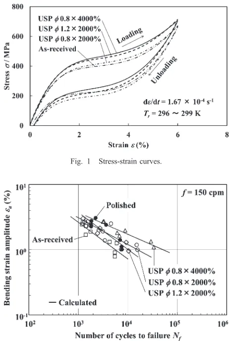
The stress-strain curves of four kinds of SMA tapes obtained by the tension test are shown in Fig. 1. All stress-strain curves draw hysteresis loops during loading and unloading, showing the superelasticity. The upper stress plateau during loading appears due to the stress-induced martensitic transformation (SIMT). In the stress plateau region, the transformation band progresses due to the SIMT in TiNi SMA tape.10) The lower stress plateau during
unloading appears due to the reverse transformation. The martensitic transformation start stress·MSwas obtained from
the intersection of two straight lines: the initial elastic part and the upper stress plateau part. Values of·MSare 370 MPa,
380 MPa, 400 MPa and 410 MPa for the as-received tape, the tape USP-treated with shot media diameterd=0.8 mm and coveragec=2000%, that with d=1.2 mm andc=2000%, and that withd=0.8 mm andc=4000%, respectively. The value of·MSincreases slightly by USP since the influence of
USP appears only on the shot-peened surface layer of the tape. Although both the shot media diameterdand coveragec
affect the value ·MS, the influence of coverage cis a little
higher than that of shot media diameterd.
3.2 Bending fatigue property 3.2.1 Fatigue life
(1) Fatigue life curve
The relationships between the bending strain amplitude¾a
and the number of cycles to failureNfforfive kinds of tapes
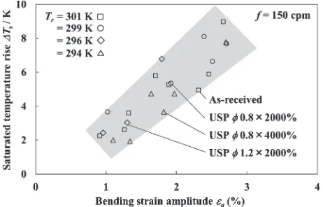
obtained by the alternating-plane bending fatigue test under a constant frequency f=150 cpm at room temperature are shown in Fig. 2. The bending strain amplitude ¾a was
obtained from the bending strain on the surface of the specimen at the fracture point. The specimen was fractured at the midpoint of two grips. As can be seen in Fig. 2, the larger the bending strain amplitude, the shorter the fatigue life is. The fatigue life of polished and shot-peened tapes is longer than that of the as-received tape. The fatigue life of the tape USP-treated with d=0.8 mm and c=2000% is almost the same as that with d=1.2 mm and c=2000%. The fatigue life of the tape USP-treated withd=0.8 mm andc=4000% is longer than that of other shot-peened tapes. The fatigue life of the tape USP-treated with d=0.8 mm and c=4000% is 2.6 times at¾a=3%and 10 times at¾a=1%longer than that
of as-received tape, respectively.
The relationships between the bending strain amplitude ¾a and the number of cycles to failure Nf shown on the
logarithmic graph are almost expressed by straight lines for all materials. The relationship therefore can be expressed by a power function as follows:
¾aNf¢¼¡ ð1Þ
where ¡ and ¢ represent ¾a in Nf=1 and the slope of the
log¾a¹logNfcurve, respectively. The values of¡and¢are
1.16 and 0.55 for the as-received tape, 1.68 and 0.55 for the polished tape, 0.52 and 0.41 for both tapes USP-treated with
d=0.8 mm at c=2000% and with d=1.2 mm at c= Fig. 1 Stress-strain curves.
[image:2.595.310.542.68.412.2]2000%, and 0.37 and 0.33 for the tape USP-treated with
d=0.8 mm at c=4000%, respectively. The calculated results of eq. (1) are shown by solids lines in Fig. 2. The overall inclinations are well approximated by the solid lines. (2) Temperature rise
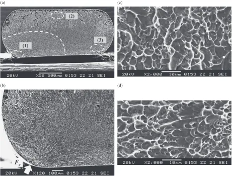
As observed in Fig. 2, the larger the bending strain amplitude, the shorter the fatigue life is. During cyclic bending, SMA is subjected to exothermic martensitic trans-formation repeatedly. Therefore, temperature of the material increases markedly in the early 2030 cycles and is saturated in a certain value thereafter.11) The difference between the
saturated temperature Tsand room temperatureTr is defined
as the saturated temperature rise¦Ts=Ts¹Tr. The
relation-ships between the saturated temperature rise ¦Ts and the
bending strain amplitude ¾afor four kinds of tapes obtained
from the test at room temperatureTr are shown in Fig. 3. In
Fig. 3, the data obtained are plotted by several symbols for each tape. The region, where the data are plotted, is shaded. Temperature rise ¦Ts increases in proportion to ¾a for all
tapes and the difference of¦Tsis slight among four tapes. As
seen in Fig. 1, the stress-strain curve of the tape draws a hysteresis loop during loading and unloading. The area surrounded by the hysteresis loop corresponds to the dissipated work per unit volumeWd.12)The dissipated work
Wd is evaluated by the product of the difference (·M¹·A)
between the upper plateau stress ·M and the lower plateau
stress·Aand the martensitic transformation strain range ¾M.
The dissipated work Wd of the surface element with the
bending strain amplitude ¾a is estimated by the following
equation13)
Wd¼ ð·M·AÞð¾a¾MSÞ ð2Þ
where¾MSdenotes the martensitic transformation start strain.
Therefore, if ¾a is large, Wd is large, and as a result large
amount of heat is generated. This is the reason why ¦Ts
increases in proportion to ¾a. In SMAs, ·M increases in
proportion to temperature as follows: d·M/dT=CM and
CM=6 MPa/K for TiNi SMA.14)It should be noticed that,
if ¦Ts is large, ·M increases. Therefore, in the practical
application of SMA elements, high ·M induced due to
temperature rise ¦Ts under cyclic bending causes large
fatigue damage, that is, the fatigue crack nucleates earlier and the fatigue crack propagate rate becomes higher, resulting in short fatigue life.
3.2.2 Fatigue crack (1) Fatigue surface
In the case of as-received tapes, the fatigue crack initiates at the central part of the flat surface subjected to maximum bending strain. In the case of USP tapes, the fatigue crack initiates at the corner different from theflat surface subjected to maximum bending strain. Let us discuss the influence of USP on the fatigue crack initiation and the fatigue crack growth by observing the fracture surface.
(i) As-received material
Figure 4 shows the SEM photograph of a fracture surface of the as-received tape obtained by the fatigue test for ¾a=1.26%. In Fig. 4, Fc denotes the point of the fatigue
crack initiation. The crack nucleates at a certain pointFcin
the central part of theflat surface of the tape and propagates toward the center in a sinuous radial pattern. Although small cracks are observed in bothflat surfaces of the tape subjected to maximum bending strain, one single crack grows preferentially. Following the appearance of fatigue crack with a semi-elliptical surface, unstable fracturefinally occurs. In the case of as-received tapes, the point Fc appears at a
central part of the flat surface subjected to the maximum bending strain and the fatigue life is short.
(ii) USP material
SEM photographs of a fracture surface for the USP tape in the case of a bending strain amplitude¾a=1.64%are shown
in Fig. 5. The tape was USP-treated with shot media diameter
d=0.8 mm and coverage c=4000%. The whole fracture surface, the fracture surface at the crack initiation part (1), the fracture surface in the middle part of unstable fracture region (2), and the fracture surface in thefinal unstable fracture part (3) located on the opposite side of the crack initiation part (1) are shown in Figs. 5(a), 5(b), 5(c) and 5(d), respectively.
As can be seen in Figs. 5(a) and 5(b), the fatigue crack nucleates at a certain point Fcin the corner (1) on the side
surface near theflat surface of the tape and propagates toward the center in a sinuous radial pattern. The distance from the flat surface of the tape to the crack initiation point Fc is
40 µm. Although small cracks are observed on four corner surfaces of the tape, one single crack grows preferentially. The reason why the fatigue crack nucleates at the corner surface is as follows. Although the maximum bending strain appears on the flat surface of the tape, the flat surface is subjected to USP and therefore it is hard for the fatigue crack
Fig. 3 Relationship between saturated temperature rise¦Ts and bending strain amplitude¾a.
[image:3.595.307.547.70.215.2] [image:3.595.54.285.71.219.2]to nucleate on the flat surface. The side surface of the tape is subjected to slight USP. As a result, the fatigue crack nucleates at the corner Fc near the flat surface. This
phenomenon is similar to the fatigue crack initiation point of a TiNi SMA wire subjected to nitrogen-ion implantation.15) In the case of an ion-implanted wire, the fatigue crack nucleates at a certain point different from the maximum bending strain point where the maximum amount of nitrogen ion was implanted. In practical applications of SMAs, the fatigue life of SMA elements increases if USP is treated not only on the surface at the maximum stress point but also on the surface in the region near the maximum stress point.
As can be seen in Fig. 5(a), following the appearance of fatigue fracture with a quarter-elliptical surface, unstable fracturefinally occurs. As can be seen in Fig. 5(c), isometric dimples with an average diameter of about 3 µm appear in the middle part of unstable fracture region (2). As seen in Fig. 5(d), elongated dimples are found distributed in the direction parallel to the flat surface according to the propagation of the crack induced by tearing in the final unstable fracture part (3).
(2) Fatigue crack growth (i) Fatigue crack growth area
Let us discuss the fatigue crack growth area Af which
is surrounded by dashed semi-elliptical or quarter-elliptical lines shown in Figs. 4 or 5(a). The relationships between the fatigue crack growth areaAfand the bending strain amplitude
¾a for four kinds of tapes obtained by the fatigue test are
shown in Fig. 6. In Fig. 6, the data obtained are plotted by several symbols for each tape. The regions, where the data are plotted, are shaded separately for the USP tape with
d=0.8 mm atc=4000%and for other three tapes. As can be seen in Fig. 6, only the area Af of the USP tape with
d=0.8 mm atc=4000% is larger than that of other three tapes. The larger the bending strain amplitude, the smaller the fatigue crack growth area is. If the bending strain amplitude is large, the fatigue crack growth area is small, resulting in a short fatigue life. In the case of USP with d=0.8 mm at
(b) (d)
Fig. 5 SEM photographs of fracture surface of USP tape withd=0.8 mm andc=4000%for¾a=1.64%andNf=6788: (a) whole fracture surface, (b) crack initiation part (1), (c) middle part of unstable fracture (2), and (d)final unstable fracture part (3).
[image:4.595.68.529.71.421.2] [image:4.595.312.543.469.617.2]c=4000%, Af is larger than other three conditions, which
corresponds to the longer fatigue life. (ii) Fatigue crack growth length
As observed in Figs. 4 and 5, the fatigue fracture surface shows a semi-elliptical or a quarter-elliptical form. Let us discuss the fatigue crack growth length along theflat surface
asfrom the crack initiation pointFcand that toward the center
ac. The dependence of as and ac on the bending strain
amplitude¾ais shown in Fig. 7. In Fig. 7, the data of asare
plotted by closed symbols and those ofacby open symbols,
respectively. The regions, where they are plotted, are shaded. As can be seen, the larger the bending strain amplitude¾a, the
smaller the crack growth lengthasis. The dependence ofac
on ¾ais slight. Values of acare around 0.5 mm, a half of a
thickness of the tape of 1 mm. Values of as are larger than
those of ac since the bending strain is largest on the flat
surface of the tape and is small in the central part of the tape. (iii) Average fatigue crack growth rate
The dependence of average fatigue crack growth rate till fracture along theflat surfaceas/Nfand that toward the center
ac/Nf on the bending strain amplitude¾afor the as-received
tape and the tape USP-treated withd=0.8 mm atc=4000% is shown in Fig. 8. In Fig. 8, the data ofas/Nfare plotted by
closed symbols and those of ac/Nf by open symbols,
respectively. As can be seen, the larger the bending strain amplitude, the larger the crack growth rates are. The average fatigue crack growth rates for the as-received tape are higher than those for the USP tape. This means the fact that the average fatigue crack growth rates decrease by the USP treatment, resulting in longer fatigue life.
3.2.3 Influence of hardness on fatigue life
Vickers hardness of the surface for four kinds of tapes was measured by a load of 49 N. The relationships between the number of cycle to failure Nf and Vickers hardness HV for
various values of bending stain amplitude ¾a are shown in
Fig. 9. In Fig. 9, the data are plotted by several symbols and the relation for each ¾ais connected by the straight line. As
can be seen in Fig. 9, the fatigue lifeNfof TiNi SMA treated
by USP increases in proportion to Vickers hardness HVas same as normal metals. The influence ofHVonNfis slight in
the case of large ¾a. The relationships shown on the
semi-logarithmic graph are almost expressed by straight lines for each ¾a. The relationship therefore can be expressed by the
following equation.
logNf ¼logaþbHV ð3Þ
where a and b represent Nf in HV=0 and the slope of the
logNf¹HV curve, respectively. The value ofb denotes the
sensibility of influence ofHVon theNf. Theadenotes the value
ofNfunaffected byHV. The fatigue lifeNfcan be expressed
by an exponential function ofHVfrom eq. (3) as follows:
Nf ¼aexpðln 10bHVÞ ð4Þ
The coefficients a and b can be expressed by the linear functions of ¾aas follows:
a¼a1¾aþa2
b¼b1¾aþb2 ð5Þ
wherea1andb1represent the slopes of thea¹¾acurve and
b¹¾a curve, and a2 and b2 represent a and b in ¾a=0,
respectively. The values ofa1,a2,b1andb2are¹86.5, 32.6,
¹0.0988 and 0.00738, respectively. The results calculated from eqs. (4) and (5) are shown by solid lines in Fig. 9. The overall inclinations are well-approximated by the solid lines. 3.2.4 Surface roughness
It is known that surface roughness of the material affects the fatigue life. If the surface is rough, the fatigue life is short.16)As observed in Fig. 2, the fatigue life of the polished
tape is longer than the as-received tape. In order to investigate the influence of surface roughness on the fatigue life, surface roughness was measured.
Fig. 7 Dependence of fatigue crack lengthsas andacon bending strain amplitude:asis shown by closed symbols andacby open symbols.
Fig. 8 Dependence of average fatigue crack growth ratesas/Nfandac/Nf on bending strain amplitude¾afor as-received tape and USP tape with
d=0.8 mm andc=4000%:as/Nfis shown by closed symbols andac/Nf by open symbols.
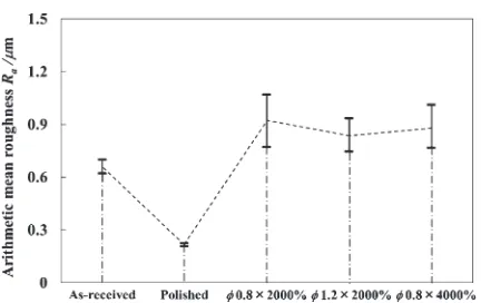
[image:5.595.318.535.71.209.2] [image:5.595.56.284.71.218.2] [image:5.595.314.538.269.424.2]Arithmetic mean roughness Ra for five kinds of tapes is
shown in Fig. 10. The value ofRafor the as-received tape is
0.65 µm. The value of Ra=0.2 µm for the polished tape is
about one-third as large as the as-received tape. As observed in Fig. 2, the fatigue life of the polished tape is longer than that of the as-received tape. Therefore, if the surface is smooth, the fatigue life is long. The values of Rafor three
kinds of USP tapes are 0.83 µm0.88 µm, which are slightly larger than that of the as-received tape. As observed in Fig. 2, the fatigue life of USP tapes is longer than that of the as-received tape. Compressive residual stresses are induced in the surface layer of the material by USP.8) Although the
surface roughness increases slightly by USP, the influence of USP-induced surface roughness on the fatigue life is slight. The reason why the USP-induced surface roughness has a small influence on the fatigue life must be due to compressive residual stresses induced by USP in the surface layer of the tape. The values of residual stress measured were among
¹80 MPa and ¹160 MPa in the region of depth from the surface to 200 µm for both the as-received tape and USP tapes. The difference of the residual stresses among the as-received tape and USP tapes was not clearly detected. This reason may be surmised as follows. The tapes were subjected to high work hardening during the rolling process to produce them and therefore high residual stresses were already induced in the material. The detail of the residual stress is the future work.
4. Conclusions
The TiNi SMA tapes showing superelasticity were USP-treated, in which both flat surfaces were shot-peened from two opposite directions, and the influence of shot media diameter and coverage on the fatigue life of alternating-plane bending was investigated. The results obtained are summa-rized as follows.
(1) The larger the bending strain amplitude, the shorter the fatigue life is. The fatigue life can be expressed by a power function of strain amplitude. The fatigue life of USP-treated tapes is longer than that of the as-received tape. The fatigue lives of both tapes USP-treated with different shot media diameters at the same coverage are almost the same. The fatigue life of the tape USP-treated with high coverage for the same shot media diameter is longer than that with low coverage.
hardness.
(4) The surface roughness increases slightly by the USP treatment. The fatigue life of polished and USP-treated tapes is longer than that of the as-received tape. (5) In practical applications of SMAs, the fatigue life of
SMA elements increases if USP is treated not only on the surface at the maximum stress point but also on the surface in the region near the maximum stress point.
Acknowledgment
The experimental work for this study was carried out with the assistance of students in Aichi Institute of Technology, to whom the authors wish to express their gratitude. The authors also wish to extend thanks to the administrators of Scientific Research (C) (General) in Grants-in-Aid for Scientific Research by the Japan Society for Promotion of Science forfinancial support.
REFERENCES
1) K. Otsuka and C. M. Wayman (eds.): Shape Memory Materials, (Cambridge University Press, Cambridge, 1998) pp. 149.
2) T. Sakuma, U. Iwata and Y. Kimura: Fatigue‘961(1996) pp. 173178. 3) T. Sawaguchi, G. Kaustrater, A. Yawny, M. Wagner and G. Eggeler:
Metall. Mater. Trans. A34(2003) 28472860.
4) M. Wagner, T. Sawaguchi, G. Kaustrater, D. Hoffken and G. Eggeler:
Mater. Sci. Eng. A378(2004) 105109.
5) R. Matsui, H. Tobushi, Y. Furuichi and H. Horikawa:Trans. ASME J. Eng. Mater. Tech.126(2004) 384391.
6) H. Tobushi, R. Matsui, K. Takeda and E. A. Pieczyska:Mechanical Properties of Shape Memory Materials, Part 2, Fatigue properties of shape memory alloy, (Nova Science Pub., New York, 2013) pp. 115 164.
7) L. Wagner (ed.):Shot Peening, (Wiley-VCH, Weinheim, 2003) pp. 1 562.
8) S. K. Cheong, D. S. Lee, J. H. Lee, M. Handa and Y. Watanabe: Proc. ICSP-10, (2008) pp. 494498.
9) H. Tobushi, K. Mitsui, K. Takeda, K. Kitamura and Y. Yoshimi: J. Theor. Appl. Mech.50(2012) 855869.
10) K. Takeda, H. Tobushi, K. Miyamoto and E. A. Pieczyska: Mater. Trans.53(2012) 217223.
11) H. Tobushi, T. Nakahara, Y. Shimeno and T. Hashimoto:Trans. ASME J. Eng. Mater. Tech.122(2000) 186191.
12) E. A. Pieczyska, S. Gadaj, W. K. Nowacki, K. Hoshio, Y. Makino and H. Tobushi:Sci. Tech. Adv. Mater.6(2005) 889894.
13) R. Matsui, Y. Makino, H. Tobushi, Y. Furuichi and F. Yoshida:Mater. Trans.47(2006) 759765.
14) K. Tanaka, T. Hayashi, Y. Ito and H. Tobushi:Mech. Mater.13(1992) 207215.
15) K. Takeda, K. Mitsui, H. Tobushi, N. Levintant-Zayonts and S. Kucharski: Arch. Mech.65(2013) 391405.
[image:6.595.62.278.66.202.2]16) J. E. Shigley and C. R. Mischke:Mechanical Engineering Design, 5th ed., (McGraw-Hill, New York, 1989) pp. 282283.