Optimization of Laser Processing in the Fabrication of Stents
Cheng-Shun Chen
1, Sheng-Yao Lin
1,+, Nai-Kuan Chou
2, Yih-Sharng Chen
2and Sheau-Fan Ma
1 1Graduate Institute of Mechanical and Electrical Engineering, National Taipei University of Technology,Taipei 10608, Taiwan, R. O. China
2Department of Cardiovascular Surgery, National Taiwan University Hospital, Taiwan, Taipei 100, Taiwan, R. O. China
Stents are commonly inserted into coronary arteries for treating cardiovascular diseases. Nonetheless, the process of manufacturing metal stents is challenging owing to the geometric design, the optimization of machining methods and the materials involved. Fiber lasers were used as the laser cutting technology for cutting stents. The experiment revealed the importance of precise technical parameters, including the lens’focal length, focus position, pulse frequency, cutting speed and pulse width. These parameters strongly influence the kerfs width and the quality of the cutting seam surface. Our results indicate that the width of the kerfs increases with an increase in the pulse frequency and pulse width, whereas it decreases or shows minimal change at higher cutting speeds. The surface roughness for stent laser cutting was Ra 43.5 nm, which essentially meets the design requirement for further performance evaluation. Finally, high-quality cutting of a 316LVM stainless steel vascular stent was achieved. [doi:10.2320/matertrans.M2012188]
(Received May 18, 2012; Accepted August 20, 2012; Published October 25, 2012)
Keywords: laser cutting, stent,fiber laser
1. Introduction
The production of high quality stents requires sophisticated technological expertise in the fields of materials science, optics, mechanics and medicine. Laser cutting is a crucial aspect of stent production, directly influencing the mechan-ical properties as well as the biologmechan-ical reaction of the body to the implanted stent. At present, Nd:YAG lasers are most commonly employed in the production and further develop-ment of surgical stents.
This study investigated the manufacturing technology and selection of parameters in the fabrication of metal stents. Numerous materials are suitable for the production of stents; however, 316LVM stainless steel is most commonly selected. A metallic stent is typically a hollow cylindrical tube (d=2 10 mm;L=1065 mm) with a structure of patterned slits in two or three segments. Producing stents with a small kerfs width requires that Nd:YAG laser be configured to operate close to their diffraction-limited performance.
Raval examined the process of cutting 316L stainless steel stents using a Nd:YAG laser, as well as the electrolytic polishing of the stent after cutting.1)After observing a heat-affected zone in the stent ribs after cutting, Sudheer adjusted the parameters of the Nd:YAG laser to enhance cutting quality.2)Kathuria provided optimized cutting parameters for short-pulse YAG lasers used for cutting 316L stainless steel stents.3,4) Schuessler compared the performance of light pump lasers, diode-pump lasers and femtosecond lasers cutting nickel-titanium, 316L stainless steel and cobalt-chromium alloy stents, focusing on the overall quality of kerfs, heat-affected zones, cutting speed and area ratio as well as the surface properties of these materials.5,6) Gachonet al. examined the influence of laser cutting accuracy on the mechanical properties of stents.7)
This research revealed the advantages and disadvantages of fiber lasers and provided considerable guidance with
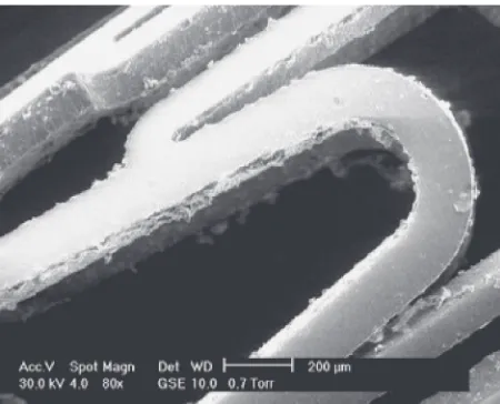
regard to their application. In particular, these studies demonstrated that Nd:YAG lasers have, thus far, been unable to provide sufficient smoothness, and often result in the formation of a large number of burrs, as shown in Fig. 1.1)
In previous studies, the author has investigatedfiber lasers to determine the optimal parameters with which to cut mesh structures by minimizing laser output energy, identifying the optimal frequency, precisely adjusting the cutting speed and fixing the defocus amount. The results are applicable in the cutting and manufacturing of thin-wall tubes and planes. Fiber lasers also help to alleviate the difficulties associated with treating the surface of stents after cutting as well as susceptibility to fractures resulting from overly small cross-sectional areas.
Fiber lasers provide myriad advantages over Nd:YAG lasers, including superior beam quality (M2 approaches 1), stable output and a long life. This study adopted afiber laser light source for the laser cutting of 316LVM stainless steel in the evaluation of specially designed stents. The mesh-structured stents feature even kerfs with an aperture of less than 12 µm (wall thickness: 0.08 mm; diameter: 3 mm).
Fig. 1 SEM images of Nd:YAG laser after cutting stents (Ref. 1)).
+Corresponding author, E-mail: sa29@ms41.hinet.net, Graduate Student,
National Taipei University of Technology
[image:1.595.314.539.322.504.2]2. Geometry and Material Properties
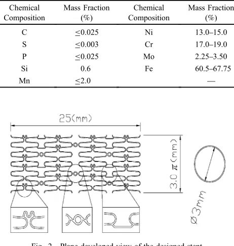
The material from which stents are produced is an important factor determining their subsequent performance. Biocompatibility, X-ray and MRI visibility, radial strength, flexibility and durability must all be considered in the performance of stents. This study selected 316LVM stainless steel, due to its wide applicability in processing of this nature. The composition of the material used in this study is consist-ent with the ASTM F138 standards, as shown in Table 1.8)
A number of key design parameters must be considered in the structural design of a stent. For stents designed in AutoCAD, each line in the stent structure must be closed without overlap; otherwise, the workpiece will be unable to withstand the process of cutting. The dimensions of the stents used in the laser cutting experiments were as follows: external diameter (D), 3.0 mm; wall thickness, 0.08 mm; and length, 25 mm, as shown in Fig. 2.
3. Research Methods
3.1 Experimental apparatus
This study employed a 100 W fiber laser precision machining system, operating at a wavelength of 1070 nm in TEM00 Gaussian mode. The laser was focused using a lens with a focal length of 30 mm, resulting in a laser spot size of 12 µm. The pulse width was adjustable from 0.05 to 0.4 ms; the repeat frequency was adjustable to 170 kHz; the maximum horizontal speed reached 40 m/s; and the positional accuracy reached 8 µm/30 mm.
3.2 Laser system and primary module
Figure 3 presents a schematic diagram of the laser cutting system, including five main modules: laser source, trans-mission module, laser focus and cutting module, workbench, and control system. The laser beam was focused on the
surface of the work piece via a beam expander, collimator and lens. The surface of the tube material was heated and melted, while auxiliary gas was passed through the tube. The movement of the work bench was used to position the workpiece in front of the beam during cutting.
Thefiber laser produces a pulsed beam of specific power and intensity, which is directed to strike the surface of the workpiece vertically. According to production and quality requirements, machining parameters were adjusted to ensure that the system demonstrated the following characteristics:
(1) The ability to process arbitrary shapes and perform three-dimensional machining.
(2) The ability to pause and preview the machine proc-essing.
(3) Precise machining with angle accuracy of 0.250°/360°. Accuracy increases during low-speed machining. (4) Machining range: plane range of 250 mm©250 mm;
rotation range of«360°.
3.3 Experiment methods
The fiber laser produces a pulse of energy, which is directed by an optical system (beam expander and focus), onto the arc surface of the 316LVM stainless steel workpiece. This study adjusted the pulse frequency, pulse width and the cutting speed of the laser to identify the optimal machining parameters. The focus position and standoff of the assist gas nozzle remained unchanged throughout the experiment. The standoff was set at 0.25 mm and the focus position was sufficient to ensure the integrity of minimum width kerfs.
3.4 Surface roughness
The surface roughness resulting from laser cutting was checked using a stereo-microscope. A scanning electron microscope was used to evaluate the effects of laser cutting. Surface topology and quantitative roughness measurements were evaluated using an atomic force microscope. The entire analysis setup was assembled on an anti-vibration device to ensure accurate roughness measurements. The evaluation area for AFM analysis was 100©100 microns.
4. Results and Discussion
[image:2.595.319.536.71.219.2]Figure 4 shows kerfs width as a function of cutting speed for laser output at various power levels. The repeat frequency was 15 kHz (fiber laser), the pulse width was 0.07 ms, and the Table 1 Chemical composition of vascular stent tube materials (Ref. 8)).
Chemical Composition
Mass Fraction (%)
Chemical Composition
Mass Fraction (%)
C ¯0.025 Ni 13.015.0
S ¯0.003 Cr 17.019.0
P ¯0.025 Mo 2.253.50
Si 0.6 Fe 60.567.75
Mn ¯2.0 ®
Fig. 2 Plane developed view of the designed stent.
[image:2.595.53.284.85.328.2]pressure of the assist gas (Ar) was 6 bar. Kerfs width increased with an increase in laser output power due to elevated power density; kerfs width decreased with an increase in cutting speed due to low power density and low gas density. The maximum cutting speed varied with output power. The machining method employed assist gas to remove burrs, protect the edges of ribs, maintain the clarity of the lens and promote the burning reaction in the cutting process.
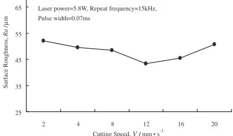
Figure 5 shows kerfs width as a function of repeat frequency for various pulse widths. The output powers of thefiber laser were 5.8 W, respectively; the cutting speed was 12 mm/s; the pressure of the assisting gas (oxygen) was 6 bar. Kerfs width increased with an increase in pulse width or repeat frequency because the reaction time between the laser beam and workpiece increased with pulse length. In addition, an increase in frequency resulted in additional energy entering the workpiece per unit of time. In other words, an increase in pulse length or repeat frequency increased the laser power density within a given unit of time. As shown in Fig. 6, an increase in cutting speed (laser output power of 5.8 W) altered the surface roughness of kerfs from coarse in the beginning tofine and then back to coarse. A low cutting speed resulted in high laser input energy, which increased the width of the kerfs. This also produced a thicker layer of molten metal, a larger number of metal burrs of increased size and a coarser surface. Setting the cutting speed too high lowered the laser input energy, which prevented the
metal in the kerfs from being entirely melted and removed. This also resulted in a rougher surface. Figure 7 presents the status of kerfs produced at various cutting speeds with the laser output power set at 5.8 W.
Figure 8 shows the effect of pulse width (0.07 and 0.10 ms) and repeat frequency (15 kHz) on surface roughness, with laser output laser power set at 5.8 W, at a cutting speed of 12 mm/s, defocus amount of 0.25 mm, and constant assisting gas pressure of 6 bar. With an increase in repeat frequency and pulse width, the surface roughness of the kerfs changed gradually from coarse in the beginning, tofine, and Repeat frequency=15 kHz, Pulse width= 0.07 ms,
Defocus amount=0.25 mm, Assisting gas=6 bar
10 15 20 25 30 0
Cutting Speed, V/ mm • s-1
K erf W idth, W / µ m Laser Power=5.8W Laser Power=7W Laser Power=9W 20 16 12 8 4
Fig. 4 Kerfs width versus cutting speed for different output offiber laser power.
Laser power= 5.8W, Repeat frequency=15kHz, Cutting speed=12 mm/s
12 14.5 17 19.5 22 5000
Repeat Frequency, f / Hz
K erf W idth, W / µ m
Pulse width 0.07 ms Pulse width 0.10ms
30000 25000
20000 15000
10000
Fig. 5 Kerfs width versus repeat frequency for different offiber laser pulse widths. 25 35 45 55 65 2
Cutting Speed, V/ mm • s-1
Surf ace Roughness, Ra / µ m
Laser power=5.8W, Repeat frequency=15kHz, Pulse width=0.07ms 20 16 12 8 4
Fig. 6 Variation in cutting speed and surface roughness.
2 mm/s
(Fiber laser power = 5.8 W) 20 mm/s 16 mm/s
12 mm/s 8 mm/s
4 mm/s
Fig. 7 Kerfs status at different cutting speeds.
Laser power=5.8W, Repeat frequency =15kHz, Cutting Speed=12 mm/s
40 45 50 55 60 65 70 5000
Repeat Frequency, f / Hz
Surf
ace Roughness,
Ra
/
µ
m
Pulse width 0.07ms
Pulse width 0.10ms
30000 25000
20000 15000
10000
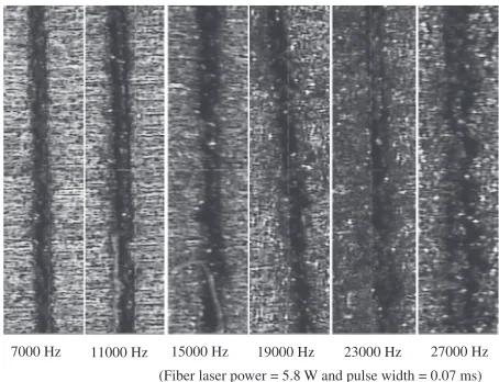
[image:3.595.312.541.78.212.2] [image:3.595.312.541.252.431.2] [image:3.595.312.539.253.607.2] [image:3.595.55.283.267.419.2] [image:3.595.320.534.469.611.2]then back to coarse. This is due to the reduction in input energy resulting from the reduced repeat frequency and pulse width. Owing to the low energy, the melted metal cannot be entirely removed, forming a rougher surface. When more energy is input by the laser, the kerfs width becomes larger, the layer of molten metal becomes thicker, and more molten metal is produced. Under these conditions, the gas cannot effectively remove the residues, resulting in a rough cutting surface. Figure 9 shows the kerfs status at different pulse width and repeat frequency at the laser output power of 5.8 W.
4.1 Laser cutting of the heat-affected zone
Figure 10 shows the surface state of the kerfs: (a) with a heat-affected zone and (b) without a heat-affected zone. The heat-affected zone was observed primarily on the surface adjacent to the cutting path, covering a width of approx-imately 1 to 2 µm. This small area is easy to clean using electrolytic polishing. The width of the heat-affected zone did not change significantly under any of the combinations of cutting parameters. Electrolytic polishing proved effective in removing the heat-affected zone, thereby minimizing the negative impact on stent performance. The size of the
heat-affected zone could be further reduced using Ar gas (without a heat-affected zone) instead of oxygen.
4.2 Optimized parameters for the cutting of stents Table 2 shows the optimized conditions for laser cutting employed in this study. A high-quality metal stent was produced at a laser output power of 5.8 W, a pulse width of 0.07 ms, repeat frequency of 15 kHz, cutting speed of 12 mm/s and assist gas pressure of 6 bar, without the need for subsequent processing, such as ultrasonic pickling. Figure 11 shows a sample obtained from the stent formed under these optimized machining parameters. The kerfs width was less than 12 µm with low roughness and a small heat-affected zone. From every angle, the surface of the kerfs appears uniform and the exterior surface clean, with no cutting spatter, burrs, or residual material.
The side surface of the stent (the cutting surface) exhibits no clear corrugation or surface residue. The heat-affected zone could not be observed directly using SEM. After cleaning, the stent satisfied the previously mentioned requirements related to cutting. The size of the rib cross-sections were the same, and the shape of the incisions matched the requirements.
7000 Hz
(Fiber laser power = 5.8 W and pulse width = 0.07 ms) 27000 Hz 23000 Hz
19000 Hz 15000 Hz
11000 Hz
Fig. 9 Different pulse widths and repeat frequency of the kerfs status.
[image:4.595.55.282.69.243.2](a) (b)
Fig. 10 Heat-affected zone of kerfs (a) is has 1.2 µm of width and (b) is without.
Table 2 Optimization parameters of laser cutting using thefiber laser.
Laser Type Fiber Laser
Wavelength (nm) 1070 nm
Repeat Frequency (Hz) 15 kHz
Laser Cutting Power (W) 5.8 W
Pulse Width (ms) 0.07 ms
Cutting Speed (mm/s) 12 mm/s
Assisting Gas (bar) 6 bar
Defocus amount (mm) 0.25 mm
Burrs and Cut Marks Not Obvious
Slag Sticking on Surface Prior to Cleaning Less
Slag Sticking on Surface After Cleaning None
Cut Marks on Side Prior to Cleaning Somewhat Obvious
Cut Marks on Side After Cleaning Not Obvious
[image:4.595.309.550.84.254.2] [image:4.595.107.491.281.480.2]4.3 Comparison of surface and roughness
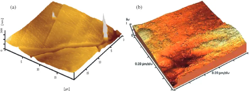
Figure 12 shows the surface roughness of stents produced using (a) fiber laser (b) Nd:YAG lasers.1) The surface roughness produced by the fiber laser was 43.5 nm, while the roughness produced by the Nd:YAG laser was 250 nm. Figure 1 shows the surface state of the stent after cutting with an Nd:YAG laser. The interior surface contains a significant quantity of slag with corrugations on the cutting side surface. This burr area is too large to remove during electrolytic polishing.
5. Conclusion
The high beam quality of the fiber laser enables a very small focus diameter and small kerfs width, making it an excellent tool for micro-cutting. Fiber lasers have many advantages over traditional lasers.
(1) The width of stent kerfs is closely related to pulse frequency, pulse width, and the cutting speed of the laser beam. An increase in the laser pulse frequency and pulse width causes an increase in the width of kerfs; kerfs width gradually decreases with an increase in cutting speed.
(2) The surface roughness of the stent after cutting is closely related to pulse frequency, pulse width, and cutting speed. The process of cutting altered the surface roughness, which changed from coarse tofine, and then back to its initial coarse state.
(3) The heat-affected zone of kerfs cut using optimized machining parameters was only 1.2 µm, which could easily be removed during follow-up processing. Fiber lasers provide excellent beam quality, resulting in smaller faculae diameter and kerfs width. The ideal parameters influencing the cutting quality have been identified, enabling the production of high-quality stents with a kerfs widths less than 12 µm.
Acknowledgment
We would like to thank Rofin Co., MUT Co. and TLT Co. for their assistance.
REFERENCES
1) A. Raval, A. Choubey, C. Engineer and D. Kothwala: Mater. Sci. Eng. A 386(2004) 331343.
2) S. K. Sudheer, V. P. M. Pillai, V. U. Nayar, Y. Pothiawala, D. Kothwala and D. L. Kotadia:J. Microlith. Microfab. Microsyst.5(2006) 023010 19.
3) Y. P. Kathuria:Proc. SPIE5399(2004) 234244.
4) Y. P. Kathuria:Proc. SPIE5142(2003) 176186.
5) A. Schuessler and M. Strobel: ASM materials & processes for medical devices conference (Anaheim, CA, 2003) pp. 135141.
6) M. Strobel and A. Schuessler: SMST conference (Baden-Baden, 2004) pp. 287293.
7) C. Gachon, P. Delassus and P. Mc Hugh:Proc. of SPIE 4876(2003) 574581.
[image:5.595.115.482.71.208.2]8) http://www.matweb.com (a) (b)
Fig. 11 SEM images offiber laser cutting after (a) prototype sample and (b) side surface.
[image:5.595.86.512.247.402.2](a) (b)