SPH Analysis of ECAP Process by Using Grain Refinement Model
Ken-ichi Saitoh and Yuuki Ohnishi
*Department of Mechanical Engineering, Faculty of Engineering, Kansai University, Suita 564-8680, Japan
Plastic working of metals using severe plastic deformation (SPD) recently attracts interest of researchers, because it is a method that will improve the toughness as well as the strength just by applying enormously large strain on the material. In this study, deformation, stress and strain of aluminum in ECAP (equal channel angular pressing) are analyzed computationally by using smoothed particle hydrodynamics (SPH) method which is one of particle methods. In addition to elastic-plastic constitutive relation, a newly developed theoretical framework in which grain refinement process is involved is proposed here. We try to implement the framework into the SPH computation. The main idea to conduct grain refinement in the material is that applied energy by plastic working causes continuous change in the total area of grain boundaries and averaged diameter in the material becomes smaller and smaller. The reasonable change can be observed by using such simple but theoretical framework. The present paper is focused on implication, formulation and possibility of the grain refinement model.
[doi:10.2320/matertrans.MD200814]
(Received July 22, 2008; Accepted September 9, 2008; Published October 22, 2008)
Keywords: severe plastic deformation, numerical analysis, smoothed particle hydrodynamics, grain refinement, equal-channel angular pressing (ECAP), plastic work, aluminum
1. Introduction
Plastic working process of metallic material using severe plastic deformation (SPD) has attracted interests of many researchers. The advantage of SPD processing is that it is capable of improving toughness of the metallic material as well as strength, just by injecting heavy deformation.1)
One of typical methods in SPD process is ECAP (equal-channel angular pressing), where a material is extruded through a die which has hollow space with angular shape.2) Since the sectional dimensions of the ECAP die at both entrance and exit are almost the same, the molded shape has the same dimension even though it has been subjected to very large strain history inside.
It is reported that experimentally ECAP processing is applied to ductile metals such as aluminum and copper alloy, which are strengthened and are toughened sufficiently. General principle of SPD is that averaged grain size in usual polycrystalline metals diminishes to very small regime by giant strain. As a results, they results in nanocrystalline or ultrafine-grained (UFG) material.3) Metallurgically and physically vital mechanisms for strengthening of the material are known so far. For example, there are entanglement of dislocation motion, trapping of moving dislocation mainly due to grain boundaries (GBs), strengthening of GBs themselves, and etc. Some studies show that there are not only such well-known mechanisms related to dislocation theory, but are also new mechanisms such as GB sliding or bending and the appearance/annihilation of non-equilibrium GBs.4,5)Therefore it is worth while clarifying the mechanism of GBs responsible for SPD processing from the viewpoint of microstructual evolution.
The viewpoint of grain refinement (GR) behavior is truly important, but is still not clear. It is expected that, by using atomistic simulation, GR mechanism will provide insight along with the detailed change of crystalline structure, where
coarse grains finally change to UFGs.6) However, at the present, atomic simulations are limited to too small region to obtain the whole aspect of GR mechanism. Therefore, it is necessary to study the microstructural change in a size larger than atomic scale. Thus, a method of numerical simulation based on the macroscopic framework is adopted in the present study.
Nowadays, computational method such as finite element (FE) method or mesh-free methods (alternatively called particle methods)7) is extensively applied to the dynamics simulation of solid materials. Our choice is the smoothed particle hydrodynamics (SPH) method, which is one of particle methods using particle approximation. We are trying to utilize it to analyze the behavior of metal forming under SPD process.
Recently, there have been some studies using the FE analysis on ECAP processing.8,9) The FE analysis has been applied widely to the plastic working problem and nowadays we have numerous sophisticated softwares. Nevertheless, the FE analysis needs very complicated treatment and theory to include contact condition, fracture criterion, or large defor-mation. The particle methods such as SPH method will be a kind of breakthrough for such complexities. For example, when the large distortion of the material appears, it is free from troublesome re-meshing (it will be inevitable in usual FE analysis). Generally, the particle methods are suitable for the formulation of large deformation. Besides, they can quite naturally integrate the contact condition.
Although the SPH method is using particles, it is still a macroscopic (i.e. continuum) simulation. Therefore it re-quires parameters for the constitutive relation which ex-presses mechanical or physical response of the material. However, an ordinary material’s law does not contain the GR behavior. To our knowledge, any constitutive model does not have a grain size as an time-evolution variable in order to express the GR behavior in SPD process. Therefore we propose the theoretical framework of GR behavior in SPD process and attempt to implement it numerically with SPH modeling.
*Graduate Student, Kansai University. Present address: Isuzu motors
limited
The basic framework of our model is as follows. In the SPD process, just like in ordinary plastic working (metal forming), the external applied energy (plastic work) alters microstructure inside material. The enlargement of the area of GBs can be focused on, because it is directly connected to GR behavior. The excessive free energy required for extension of GB region is supplied from a part of the plastic work which has been done on the material. The famous Hall-Petch law which provides the relation between the averaged grain size and yield stress tends to raise the yield stress of the material. When there is also work hardening behavior, in a certain part the change due to the plastic work will become small eventually and the GR behavior will cease to proceed where grains have a certain grain size.
In the present paper, it is shown that the results are strongly affected by the existence of grain-size evolution. The purpose of this paper is to show the implication of theoretical formulation of GR mechanism and to discuss its possibility for analyzing SPD behavior.
This paper is organized as follows. In the next section, some basic concepts of SPH method needed for the analysis of plastic deformation are shown. Then our proposal about the formulation of GR mechanism is presented. Also the detailed computational model of ECAP processing by using SPH method is shown. In the subsequent section, results are shown and discussed. Finally, concluding remarks are shown.
2. Theory and Method
2.1 SPH analysis for elastic-plastic solid materials In the present study, the smoothed particle hydrodynamics (SPH),10–12) which is one of particle methods (mesh-free methods) for dynamics of materials, is used. The SPH method was originally introduced for astrophysical problem such as coalescence between galaxies or between stars. Then it has been developed to be applied to various fields of mechanics and dynamics.13,14)The problem called ‘‘tensile instability’’ can be overcome by many methods15,16)and the SPH method is now developing to a broad and main frame-work of particle methods.7)In the method, time-evolution of particle systems, as though in molecular dynamics (MD) atomic trajectories are solved through equations of motion, are determined by interaction between particles. The dis-crepancy between SPH and MD is that particles of SPH mean only non-existing lumps of the material, each of them having local physical values. Therefore, their interaction is to be determined within macroscopic (continuum) relation, in the same way as in the FE formulation.
The advantage of particle methods is that they do not require any mesh but particles. This fact enables the SPH method to deal easily with large deformation, rupture and fracture sometimes we see actually. Indispensable equations to be solved in SPH analysis are the equations of motion. The equation of motion of each particle is approximated and dis-cretized by a so-called kernel function, by which superposi-tion of interacsuperposi-tion between neighbors is carried out. For solid materials, equation of motion of the particleiis given by,
dv i
dt ¼
X
j
mj
i
2 i
þ
j 2
j
þij
!
Wij;; ð1Þ
where j particles are in the range of interaction around i
particle. Subscriptsandindicate the Cartesian coordinate components (i.e. ; ¼1;2;3¼x;y;z) and v
i;mi; i; i
are the velocity, the mass, the density and the stress tensor of the particlei, respectively.Wijis the kernel function between
iandjparticles and in the present study a limited-range cubic spline function is adopted. In the equation of motion, the derivative of kernel function Wij; (the comma before the
coordinate indexmeans the derivative) is used.ijis called
the artificial viscosity which is required to avoid inadequate overlapping of particles.
In order to reproduce reaction in the solid material, stress value has to be updated at every time step. That is, in addition to equations of motion, variation of stress (internal force) should reflect the deformation (strained) state at each material’s point. The incremental approach with the formu-lation of large deformation is applied to the present study. Using elastic-plastic coefficient matrix De p, incremental stress is determined by
d¼De pd"; ð2Þ
whered"is strain increment. Switching from elastic analysis to plastic one is carried out particle to particle, by comparing Von-Mises’s equivalent stress with a yield stress y. Because the length of paper is limited, we have to omit the detailed explanation concerning the formulation of De p. In brief, however, the required material constants are yield stress y, Young’s modulus E, Poisson’s ratio , plastic constantCand strain hardening exponentn(they are listed in describing the SPH model in later section). The strain tensor of particle i,"i , is estimated based on the kernel approx-imation17)as,
_ "
"i ¼X
j 1
2 ðv
j v
iÞWij;þ ðv
j v
iÞWij;
n o
ð3Þ
wherevi;vjare particles’ velocities.
The difficulty of SPH for plasticity is that the original method does produce compressibility. Therefore, SPH method has been improved by Sakai et al. to comprise incompressible condition by using the SMAC (simplified marker and cell) algorithm,18)which is a famous technique in fluid dynamics analysis. The modified version is called ‘‘SMAC-SPH’’ and the present study utilizes its framework. In the SMAC-SPH, after particles move according to a constitutive law and dynamics, the velocity and the position of particles are modified so as to fulfill incompressible condition in all. This modifying stage adopts implicit algorithm and so finally all positions and velocities become consistent with a given constitutive relation.
2.2 A simple model of grain refinement
In polycrystalline metal, change in grain sizedis supposed to be caused by numerous kinds of physical or mechanical condition, e.g. temperatureT, timet, stress tensor, plastic strain "p, deviatric stress p, mean stress m. Indeed, in a strict treatment, grain sized can be presented by a function
d¼dðt;T;;p; m;"p;_;pp_;_m;"p"_ ; Þ: ð4Þ
refinement behavior. Therefore, first, we assume that d
depends on plastic work densitywp defined as,
wp¼
Z "p
0
d""; ð5Þ
which is composed of equivalent stress and increment of equivalent straind""within plastic regime. That is,wpmeans total energy (work) density injected into the material during the processing, excluding elastic contribution which will disappear after the processing.
The wp results in the evoluting microstructure inside the material. The change would contain various mechanism, such as dislocation motion, formation of dislocation cell, creation and annihilation of voids or vacancies, GB migration, nucleation of new GBs, and these combination. Besides, most of the injected energy will be dissipated as heat and be lost eventually. Thus, plastic work can be presented as
wp¼eGBþedefectsþeheatþeother; ð6Þ
whereeGB,edefects,eheatandeotherare increase of GB energy, increase of defects energy including dislocation motion, heat dissipation, and other, respectively. In considering SPD processing, the creation of GB should be focused on. Since the creation of new GB is equivalent to increase of GB area and hence it means small grains, it automatically reflects the GR mechanism. Thus, increase of GB energy eGB can be related to total plastic workwp in linear form as,
eGB¼wp ð7Þ
where is an arbitrary factor less than unity which determines the contribution. In practical use, will have to be specified by comparison with experiment. Since there is large amount of heat dissipation, it is reasonable that be very small, such as 10% or less, even though we do not have any reliable way to estimate it now. Anyway, by using a certain small fraction number, we are capable of estimating the amount of expansion of GB area and its energy.
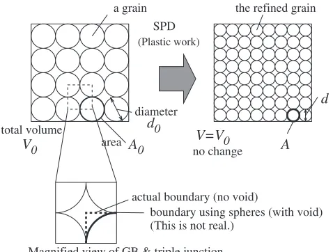
Figure 1 shows a conceptual relationship between GB area (A) and the grain size (d). It assumes that in the total volume all the grains are regularized and is closely packed by polyhedora which have the same volume as sphere of grains shown there (since the seamless packing of spheres is impossible in reality, we just assume that the volume of one sphere is equivalent to one polyhedron of grain.). Reduction of the averaged grain size corresponds to the increase of the GB area. This formulation is possible in full three-dimensions, of course, but two-dimensional formulation is shown here suitable for the present two-dimensional SPH model. That is to say, spheres are recognized as cylinders under the plane strain condition.
Suppose that regular-sized grains with diameterd occupy a volumeVin the material. When GB energy is(per area), GB energy density (per volumeV) will be given using only
andd by,
1
2
A
V ¼
1
2ðdÞ
d2
4
¼2
d : ð8Þ
The factor 1/2 is needed, because all GB has to be made by two surfaces of spheres meaning grains. Then, when initial grain size wasd0and changed to the current sized, assuming
the GB energy is unchangeable, increase of GB energy density is calculated by,
eGB¼ 2
d
2
d0
ð9Þ
Consequently, the grain size d can be expressed by the function of plastic work densitywp. The expression is,
d¼ 2
wpþ
2
d0
: ð10Þ
It means that grain size d is simply determined by initial diameterd0, GB energyand plastic work densitywp. In this expression, larger accumulation of plastic work derives smaller grain size.
Now, for grain diameter over 100 nm, yielding stressyis related tod so thatyincreases with decrease of grain size. This is realized by an empirical law known as the Hall-Petch relation,
y¼y0þKd
1
2; ð11Þ
where y0 and K are constant values. According to this
relation, when the material begins to accumulate larger plastic strain, plastic work wp increases and d decreases. After that, many SPH particles which has experienced work hardening will be easily brought back to elastic regime. Then,
wp reaches a limited value, and grain sized also settles at a certain small value. The point is that expression of grain size
d (eq. (10)) together with this Hall-Petch relation (eq. (11)) realizes plausible distribution of grain size, dmin <d <d0
(from the UFG to the coarse-grained). In the same way, the strain hardening exponentnis also assumed to be determined by grain sizedas,
n¼n0þKnd 1
2; ð12Þ
wheren0andKn are constant values again.
2.3 Computation model of SPH simulations
Referring to the ECAP process schematically shown in d SPD
actual boundary (no void) a grain
A0 V=V0
area d0 diameter
A the refined grain
(Plastic work)
Magnified view of GB & triple junction
boundary using spheres (with void) (This is not real.)
no change total volume
V0
Fig. 1 Conceptual relationship between increase of grain boundary (GB) area and reduction of grain size (d) in a regular polycrystalline structure.
[image:3.595.308.547.73.254.2]Fig. 2(a), computational model for SPH analysis was con-structed as Fig. 2(b). It is reported that in the ECAP method a strong processing zone of SPD deformation (shown by area ABC in the figure) is formed at the corner.19,20)The region is called plastic-deformation zone (PDZ). The external curve (curve AC) contours so-called ‘‘dead metal’’ region at the outer corner, but the effect and size of PDZ is not well known. Therefore, the angle for PDZ shown in Figs. 2(a), 2(b) is varied from 0 to 90 in our model. The results are
compared with regard to . Larger corresponds to larger PDZ. Without a round corner, the outer corner have a ‘‘dead metal’’ to make the material flow smoothly. Accordingly, the flow in the round corner with larger resembles one with larger ‘‘dead metal’’ region.
Table 1 shows material constants and parameters for our model. The material is aluminum (Al) and the GB energy
¼0:324J/m2 is adopted. This value of is usually obtained for that of symmetrical low-energy GB (¼3 CSL). Other computational parameters are shown in Table 2. The contribution factor ¼0:1ð¼10%Þ is used. Constants
needed for the Hall-Petch relation (eq. (11)) and strain hardening exponent (eq. (12)) are roughly derived from an experimental fact. The fact says that, when grain size 10mm reduces to 1mm, yield stressy¼26:5MPa raises to almost 2y(twice). Likewise, we assumes that thennincreases to2n. The constants,y0,K,n0,Knused in eq. (11) and eq. (12) are
determined so as to fulfill these values. The initial valuenis obtained from experimental value of an annealed alumi-num21)and is somewhat different from that of practical 10mm grains. However, we would like to see the qualitative change ofd with the change ofn.
Actual ECAP processing is composed of repeated passes through the same die. In the present model, however, the specimen is just once pressed onto downward (ydirection in Fig. 2) by moving a ram (a plunger) with constant velocity
V. This is for simplicity, so here we do not discuss about the effect of multi-pass ECAP.
3. Results and Discussion
3.1 Behavior of particles in ECAP processing: without
GR model
Figure 3 shows the material flow for the model of ¼0,
in which no GR model is comprised. In the upper figures, spheres lightly shading are in the plastic analysis, distin-guished from the elastic particles which are shown in darker
process zone angle ψ ram
die material
die
y
x
die wall particle (aluminum)
additional die
material magnified view (corner)
l=46mm
mat.
h( )=6
w=10
l=46
h( )=30
ram
w=10
particle (steel die)
channel
length unit= mm
t= 3
ψ
die process zone
approximation 2–D plane strain
ECAP processing
Outline of ECAP process SPH modeling of ECAP
A
C B z
x y
xz rotation adding V
ram
material
(a) (b)
[image:4.595.123.474.75.266.2]Fig. 2 Computation model for SPH simulations.
Table 1 Material constants and parameters for grain refinement (GR) model.
parameter variable/unit value
Billet Die/Ram
Young’s modulus E/GPa 71.0 206.0
Initial yield stress y/MPa 265.0 400.0
Density /kg/m3 2700 2700
Poisson’s ratio /— 0.34 0.30
Plastic coefficient C/— 7.37 10.0
Work hardening exponent n/— 0.27 0.5
Initial grain size d0/mm 10.0 —
Constant (for Hall-Petch) K/MPapffiffiffiffim 3:875102 —
Constant (for Hall-Petch) y0/MPa 14.25 —
Constant (for exponentn) Kn=pffiffiffiffim 3:949104 —
Constant (for exponentn) n0/— 0.145 —
Contribution factor /— 0.10 —
[image:4.595.307.549.329.452.2]Grain boundary energy /J/m2 0.324 —
Table 2 Computation condition for SPH calculation.
property (variable)/unit values
Width of billet /mm 10.0
Width of die /mm 47.5
the number of particles /— 2303ð ¼0
Þ
2406ð ¼90Þ
Velocity of pressing V/m/s 1.0
Time increment t/s 1:0107
Total ram stroke /mm 20:0{30:0
Initial distance between particles Rx/mm 0.5
[image:4.595.46.291.340.528.2]gray. On the other hand, lower figures superposes the equiv-alent plastic strain""pwhich is evaluated at the point of each particle. After plastic region appears at the center of the processing zone of PDZ as predicted in Fig. 2(a), it spreads forward over the horizontal (2nd) channel. The front edge of the material has an inclined angle, because the material at the bottom is more pushed forward than in the upper material. Higher value in the distribution of""pappears in a parallelo-gram shape emphasized in Fig. 3(b) (indicated in cases of
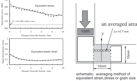
[image:5.595.47.286.75.209.2]D¼10 and 20 mm). On the other hand, region recovered back to elastic is found just in the small region of front edge. Figure 4 shows the distribution of ""p and which are averaged in the area within 10 mm forward from the inner corner of the die. Each averaged region is a slab shape having thickness ofy¼0:05mm alongydirection as shown inside Fig. 4 (on the right). In very vicinity of the bottom wall,""p raises to twice. Equivalent stress shows adequately the range 280–290 MPa, in which the bottom wall has larger value.
Quantitatively, the value range of""pis much smaller than that computationally predicted by FE analysis in usual condition of ECAP processing where""p ranges1{2.20)It is guessed that this is because we do not include wall friction model nor strict relation in the material of billet. By adjusting these conditions to the real experiments, the results will come to quantitatively plausible range of ""p. In SPH simulation, interaction between particles of die and those of the material is capable of being adjusted to realistic friction,22)but we do not include it to this SPH model. Hence, here, we will be able to discuss our results only in qualitative sense.
[image:5.595.305.546.76.218.2]3.2 Results using GR model
Figure 5 shows the material flow of the model which is applied grain refinement (GR) model (in the case of ¼0),
with distinction of plastic particles or with the value of ""p (equivalent plastic strain). When comparing these with the results without GR model shown in Fig. 3, it is found that many particles recover back to elastic regime from plastic regime. This is because plastic work given by pressing once produces smaller d at the process zone, then accordingly yield stressyincreases due to those smallerdthrough Hall-Petch relation, and consequently particles need still larger strain to remain in plastic analysis. Interestingly, ahead the D=10.0 mm
D=2.0 mm D=20.0 mm
material’s front edge
0.000
0.042 0.083
0.125
0.167
0.208
0.250 D=10.0 mm
D=2.0 mm
With distinction of plasic/elastic regions
With equivalent plastic strain distribution
material’s front edge
(D: ram stroke) D=20.0 mm
plastic plastic plastic
Plastic Elastic
78 degrees (a)
(b)
(D: ram stroke)
Fig. 3 Material’s flow of the model with ¼0 and without grain
refinement model.
∆y=0.5 mm
y
10mm
10mm
ram
schematic: averaging method of equivalent strain,stress or grain size
an averaged area
y
σ=265 MPa (initial value) Equivalent stress
Equivalent plastic strain
260 270 280 290 300
0 2 4 6 8 10
0 2 4 6 8 10
Distance from the bottom /mm
Equivalent stress /MPa
0 0.2 0.4 0.6 0.8 1
Distance from the bottom /mm
Equivalent plastic strian
Fig. 4 Distribution of equivalent plastic strain for ¼0with no grain
refinement model (the direction of inspection is perpendicular to the longitudinal direction in the horizontal channel).
D=10.0 mm D=2.0 mm
edge material’s front
D=20.0 mm (D: ram stroke)
0.000 0.042 0.083 0.125 0.167 0.208 0.250
D=10.0 mm D=2.0 mm
With distinction of plastic/elastic regions
With equivalent plastic strain distribution
D=20.0 mm (D: ram stroke)
material’s front edge
elastic elastic
plastic plastic
plastic
Plastic Elastic
74 degrees (a)
(b)
Fig. 5 Material flow with grain refinement (GR) model for the model with
[image:5.595.48.287.232.375.2] [image:5.595.305.550.289.419.2] [image:5.595.305.549.381.573.2]process zone (PDZ) at the die corner, most particles recover back to elastic regime.
As a result, the front edge of the material inclines more than for the model without GR. The angle to the horizontal line changes from 78 to 74 degrees as shown in Fig. 3 and Fig. 5, respectively. This is partly because the effect that the pressed material is pushed forward by spring-back behavior beyond the process zone is larger in the bottom region. Indeed, ""p increases drastically at the entrance of process zone, but, passing through the corner between channels, particles with large ""p begin to scatter and the distribution loses obvious parallelogram meaning intensive area, different from Fig. 3(b).
Figure 6(a) shows the grain size distribution. The smaller grains start at the center of the process zone. The region in which grains are made small corresponds to the region which has larger ""p. Ahead the corner of the die, the strong GR behavior is found along the bottom wall line (the area is emphasized by small broken lines).
Figure 6(b) shows the distribution of grain size along the line perpendicular to the channel (with the same averaging as Fig. 4). Grain size monotonically increases from the bottom wall to the upper wall. Although the grain diameter begins with 10mm, the minimum diameter is found down to 3mm near the bottom wall. On the other hand, nearby the upper wall the diameter remains 6{7mm. That is, the difference in refinement behavior is more than twice between upper and lower dies. This result agrees well with FE analysis.23)
4. Effect of the Process Zone Angle
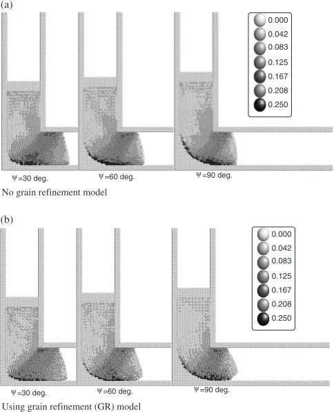
Figure 7 shows the difference of materials flow for the
variation of the angle (30, 60 and 90), with GR and
without GR models. Basically, larger the is, the more smoothly the material flows. The position of top of the ram is not at the same height because the pictures are tried to compared at the same ram stroke (D¼10mm) from the starting time at which the head of the material begins to interfere with the PDZ. Actually, the flow seems smooth in any , but the intensity of ""p or grain reduction obviously decreases with increase of the angle .
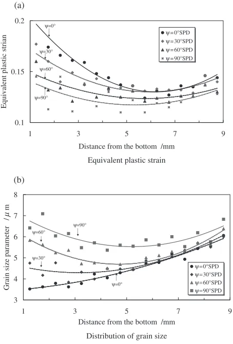
For GR model, the distribution of ""p (equivalent plastic strain) and the distribution of grain size d are shown in Figs. 8(a) and 8(b), respectively. The averaging method is the same as Fig. 4. Since in any case""pbecomes steeply large in regions very close to the two die walls, graphs here omit the value in those wall regions.
When is small, i.e. the outer corner of the die is sharp,
"
"p comes to large in upper region of the channel. On the
other hand, is large, i.e. the outer corner is round, ""p diminishes on the whole region. This is because the channel with round corner makes the stream line of the material smooth and makes the flow easy. When the outer corner is sharp, the material flow tends to stagnate at the outer corner region and forms ‘‘dead metal zone’’ there. Therefore, when the die itself has the round corner, the outer curve of the die works just alike an interface between the material and the dead metal. In all cases, the center of channel has a minimum in""p.
Figure 8(b) indicates that grain size distribution strongly depends on . When ¼0, the grain size d is monotoni-D=10.0 mm
D=2.0 mm
Time evolution of grain size distribution
Averaged grain size along y direction shown in Fig.4 grain refinement
strong
material’s front edge
D=20.0 mm (D: ram stroke)
d=10.0 d=8.4 d=6.8 d=5.2 d=3.6 d=2.0 d=0
(a)
(b)
3 4 5 6 7 8
0 2 4 6 8 10
Distance from the bottom /mm
Averaged grain size
d
/
µ
m
Fig. 6 Grain size distribution by using grain refinement (GR) model for
¼0.
=60 deg.
ψ ψ=90 deg.
=30 deg.
ψ
0.000
0.042 0.083
0.125
0.167
0.208
0.250
=60 deg.
ψ ψ=90 deg.
=30 deg.
ψ
0.000
Using grain refinement (GR) model No grain refinement model
0.042 0.083
0.125
0.167
0.208
0.250 (a)
(b)
Fig. 7 Dependence of material flow on angle (shading indicates intensity of""p). The height of ram is different because its initial position is also
[image:6.595.306.548.75.373.2] [image:6.595.50.286.75.296.2]cally increase from bottom die (the left in the figure) to upper die (the right in the figure). In other words, the intensity of GR is stronger near the bottom die than near the upper die. However, when is large, GR is hard to be carried out nearby the bottom die. Especially when ¼90,
coarse grains (larged) still remain the bottom region in the material. Thus, in the horizontal channel, the material flow becomes smoother by using GR model. Hence in GR model, grain refinement tends to be confined in the center of the material.
The intensity of GR becomes the largest in the case of ¼0 which shows large ""p and stagnating flow. This means that there is a reverse relation between the smoothness of the material flow and the grain refinement behavior.
In the actual experiments, the grain size dmin obtained in SPD processing is typically discussed in sub-micrometer regime.1) In our case, d
min stops at around 3mm which is larger than in such experiments. In our cases, parameter setting for initial diameterd0, yield stressywith Hall-Petch
relation, or strain hardening exponent n is so-to-speak temporary. However, we can obtain qualitative evaluation concerning the existence of GR model and clarify the effect of variation in . So, we should expect that further study will quantitatively survey the effect of these parameters referring more to actual SPD processing, based on the framework proposed in our model.
5. Conclusion
In the present study, we perform numerical simulations using smoothed particle hydrodynamics (SPH), for the ECAP (equal-channel angular pressing) processing which is one of promising severe plastic deformation (SPD) methods. The vital physical behavior common to SPD processes is that the grain size reduces during heavy deformation (we call it grain refinement: GR). We consider a simple relation between injection of plastic work and expansion of grain boundary energy. Then we formulate a certain ‘‘GR’’ model for the macroscopic framework of SPH simulation with large deformation. The major findings are as follows.
(1) Our formulation involving a simple GR relation works well so as to present plausible evolution of grain size occurring in ECAP processing.
(2) Strong plastic deformation is found in a region so-called PDZ (process deformation zone). It starts at the connecting region between the inner and outer corners. The angle which characterizes the size of process zone affects the flow of the material as well as the plastic strain inside. Larger produces smooth flow, but it goes with weak GR behavior.
(3) When using GR model, equivalent plastic strain becomes small in regions nearby wall. It leads to strong reduction of grain size in the center of the material. The reduction of grain size is saturated at some level (initial diameter 10mmchanges to the final 3mm).
Acknowledgments
This work was supported by KAKENHI 18062004 (Grant-in-Aid for Scientific research on Priority Areas). Part of this work was supported by HRC, Kansai University and reserach group of ORDIST, Kansai University. The authors also acknowledge Prof. Sakai (Yokohama National University, Japan) for the discussion about numerical implementation of SMAC-SPH method. One of the authors (KS) also acknowl-edge Prof. Liu (Northwestern University, USA) for the fruitful discussion and suggestion about using particle method in solid mechanics problem.
REFERENCES
1) R. Z. Valiev, Y. Estrin, Z. Horita, T. G. Langdon, M. J. Zehetbauer and Y. T. Zhu: JOM (2006) 33–39.
2) Y. Iwahashi, J. Wang, Z. Horita, M. Nemoto and T. G. Langdon: Scr. Mater.35(1996) 143–146.
3) Z. Horita (ed.):Nanomaterials by severe plastic deformation, (Uetikon-Zurich, Switzerland: Trans. Tech. Publications, 2005).
4) A. Nazarov, A. E. Romanov and R. Z. Valiev: Acta Metall. Mater.41
(1993) 1033–1040.
5) N. Q. Chinh, P. Szommer, T. Csanadi and T. G. Langton: Mat. Sci. Eng. A434(2006) 326–334.
6) R. Matsumoto, T. Hayashida and M. Nakagaki: J. Soc. Mater. Sci. Japan55(2006) 693–699.
7) S. Li and W. K. Liu: Appl. Mech. Rev.55(2002) 1–34.
8) J.-Y. Suh, H.-S. Kim, J.-W. Park and J.-Y. Chang: Scr. Mater. 44
(2001) 677–681.
9) W. J. Zhao, H. Ding, Y. P. Ren, S. M. Hao, J. Wang and J. T. Wang: Mater. Sci. Eng. A410/411(2005) 348–352.
10) L. B. Lucy: Astron. J.82(1977) 1013–1024.
11) J. J. Monaghan: Annu. Rev. Astron. Astrophys.30(1992) 543–574.
(a)
(b)
Equivalent plastic strain
Distribution of grain size 0.1
0.15 0.2
1 3 5 7 9
Distance from the bottom /mm
Equivalent plastic strian
ψ=0°SPD ψ=30°SPD ψ=60°SPD ψ=90°SPD ψ=0°
ψ=90° ψ=60° ψ=30°
3 4 5 6 7 8
1 3 5 7 9
Distance from the bottom /mm
Grain size parameter /
m
µ
ψ=0°SPD ψ=30°SPD ψ = 60°SPD ψ=90°SPD ψ=0°
ψ=90° ψ=60°
ψ=30°
Fig. 8 Equivalent plastic strain""pand grain sizeddistribution for various
[image:7.595.56.283.74.409.2]12) W. G. Hoover and H. A. Posch: Phys. Rev. E54(1996) 5142–5145. 13) L. D. Libersky, A. G. Petschek, T. C. Carney and F. A. Allahdadi:
J. Comp. Phys.109(1993) 67–75.
14) P. W. Randles and L. D. Libersky: Comput. Methods Appl. Mech. Eng.
139(1996) 375–408.
15) J. J. Monaghan: J. Comp. Phys.159(2000) 290–311.
16) P. W. Randles and L. D. Libersky: Int. J. Num. Methods in Eng.48
(2000) 1445–1462.
17) K. Shintate and H. Sekine: Composites: Part A35(2004) 683–692. 18) Y. Sakai and A. Yamashita: Trans. JSME., Ser. A67(2001) 1093–
1102.
19) G. M. Stoica, D. E. Fielden, R. McDaniels, Y. Liu, B. Huang, P. K. Liaw, C. Xu and T. G. Langdon: Mater. Sci. Eng. A410/411(2005) 239–242.
20) W. Wei, A. V. Nagasekhar, G. Chen, Y. Tick-Hon and K. X. Wei: Scr. Mater.54(2006) 1865–1869.
21) N. Noda and T. Nakamura: Kiso soseirikigaku, (1991), 19, Nissin-syuppan (Japan).
22) H. Fukumoto, K. Saitoh and N. Shinke: Proc. Computational Engineer-ing Conference (JSCES112005) 49–52.