1
Faculty of Science and Technology,
Biomedical Engineering
Ischemic core:
A method to analyse cell swelling
Martina Lamberti M.Sc. Thesis December 2019
Supervisor:
dr.ir. J. le Feber
Committee members:
Acknowledgements
I am deeply grateful for everything I learned and all the people I had the chance to meet during my master thesis project. First of all, I would like to thank Michel van Putten, for giving me the possibility to join the CNPH group and for always being available helping me with interesting suggestions. A great thanks goes also to Lejla Alic for dedicating a lot of her time in helping me by giving plenty of constructive feedback. I am extremely grateful to my supervisor Joost le Feber. Thank you for always sharing your opinion with me, for inspiring me with your knowledge, your in-teresting questions and your endless positivity. Many thanks to Marloes and Gerco, without you i would have been lost in the lab! Thanks for being there and helping with your contagious enthusiasm. Thank you to the entire research group for wel-coming me from the first day! A heart felt thank you goes to my office mates for all the laughs and the companionship! It was amazing to share this path with you. I would never thank enough all the amazing people I met here in Enschede!
Grazie a tutti i miei amici in Italia che mi supportano e sopportano da anni! A Sara che c’´e da quando ero ancora nella pancia di mia madre, e a Clelia che da 25 anni ´e sempre pronta a dirmi ci´o che pensa! Grazie a Greta, Federico, Marta, Matteo, Luca e Alessia che dal liceo (o poco dopo) continuano ad esserci nonostante la distanza! Grazie a Giorgio per aver creduto in me convincendomi a studiare ingegneria! Non ci sono parole per esprimere l’eterna gratitudine nei confronti della mia famiglia. Un grazie speciale va alla famiglia Pettoello per tutto l’aiuto datomi! Grazie alle due donne piu forti che conosca, nonna Annamaria e nonna Nuccia! Grazie per avermi insegnato a essere coraggiosa! A nonno Lucio per esserci sempre! Un grazie infinito va a nonno Costantino per aver sempre creduto in me, per avermi insegnato a difendere le mie opinioni sempre e ad ascoltare con attenzione con giudizio le opinioni altrui! Grazie a mia madre e mio padre, Eleonora e Maurizio, per ascoltarmi, consigliarmi, amarmi sempre, senza di voi non sarei mai potuta arrivare qui! Vi voglio bene! Infine un grazie va al mio fidanzato Lorenzo. Grazie per starmi vicino nelle giornate no cos´ı come in quelle si! Sono fortunata ad averti incontrato!
I am a really lucky person for having all of you in my life! Thank you all! Allemaal bedankt! Grazie a tutti!
Summary
Stroke is one of the most common causes of death. Ischemic stroke occurs due to the reduction of blood flow in the affected area of the brain. The reduction of blood supply causes a lack of oxygen inducing a shortfall of ATP production. In the core of the infarct, center of irreversible damages, the dysfunction of the sodium-potassium pump and, as a result, the influx of water inside the cells lead to cell swelling and necrotic cell death. To understand if there might be a possibility for future treatments in this region, the first step would be to quantify cells swelling. The present study aims to design, validate and apply a new method for quantifying changes in cells size in the ischemic core.
To analyse cell swelling, ischemia was induced in in vitro cultures of rat cortical
neurons, by incubating the cell with 10mM sodium-azide (NaN3) and 5mM 2-deoxy-D-glucose for 10 minutes. After verifying that this procedure did not enhance apop-tosis, cell swelling was assayed by acquiring fluorescent images with an inverted microscope every 30 seconds for 10 minutes. Fluorescence was obtained using a CellTracker green live staining. Two-dimensional images were analysed using an inhouse developed algorithm, with the purpose to identify all individual cells, and to determine their size and size changes during chemical ischemia. The algorithm was validated acquiring fluorescent images of blue microbeads with known diameter.
The number of swollen cells under ischemic conditions was significantly larger than under control conditions. Around 21% of ischemic cells showed cell swelling. Their area reached an increase of about 20% of the initial size. These results show that the chosen method of chemical ischemia leads to cell swelling. Furthermore the designed algorithm is able to determine the correct size of cells in the x-y plane, as well as temporal evolution of this area. It is possible that swelling occurred only in a specific subset of cells, e.g. only astrocytes. Moreover, it might be that, in some cells, swelling remained undetected because it occurred predominantly in the vertical direction, perpendicularly to the observed plane.
Contents
Acknowledgements iii
Summary v
List of acronyms ix
1 Introduction 1
1.1 Motivation and background . . . 1
1.1.1 Motivation of the study . . . 1
1.1.2 Cerebral ischemia and cell swelling . . . 2
1.2 Goals . . . 4
2 Materials and methods 5 2.1 Cell preparation . . . 6
2.2 Image acquisition setup . . . 6
2.2.1 Setup to validate the algorithm for cell-size assessment . . . . 6
2.2.2 Setup to validate chemical ischemia protocol and for assess-ment of cell swelling . . . 7
2.3 Algorithm for cell size assessment . . . 7
2.4 Chemical ischemia . . . 10
2.5 Experiments . . . 12
2.5.1 Validation of chemical ischemia protocol . . . 12
2.5.2 Validation of algorithm for cell-size assessment . . . 12
2.5.3 Assessment of cell swelling . . . 13
2.5.4 Statistical analysis . . . 14
3 Results 15 3.1 Validation of chemical ischemia protocol . . . 15
3.2 Validation of algorithm for cell size assessment . . . 16
3.3 Assessment of cell swelling . . . 17
3.3.1 Swollen and non-swollen cells . . . 17
3.3.2 Group comparison . . . 18
VIII CONTENTS
4 Discussion 20
4.1 Validation of chemical ischemia protocol . . . 21
4.2 Validation of algorithm for cell size assessment . . . 21
4.3 Chemical ischemia effects . . . 22
4.4 Further research . . . 24
5 Conclusions 25 References 27 Appendices A Appendix A 31 A.1 Algorithm: MATLABscript . . . 31
B Appendix B 33 B.1 Stock solutions . . . 33
C Appendix C 35 C.1 Chemical ischemia results: Ischemia group. . . 35
C.1.1 experiment 1 . . . 35
C.1.2 experiment 2 . . . 36
C.1.3 experiment 3 . . . 37
C.1.4 experiment 4 . . . 38
C.1.5 experiment 5 . . . 39
C.1.6 experiment 6 . . . 40
C.1.7 experiment 7 . . . 41
C.1.8 experiment 8 . . . 42
C.1.9 experiment 9 . . . 43
List of acronyms
ATP Adenosine Triphosphate
MRI Magnetic Resonance Imaging
CT Computed Tomography
OGD Oxygen and Glucose Deprivation
DMEM Dulbecco’s Modified Eagle Medium
2-DG 2-deoxy-D-glucose
PBS Phosphate-Buffered Saline
DNA Deoxyribonucleic Acid
PI Propidium Iodide
RGB Red Green Blue
Chapter 1
Introduction
1.1 Motivation and background
1.1.1 Motivation of the study
Ischemic stroke is one of the most common causes of death in Europe [1]. Stroke is a condition caused by a sudden decrease in blood supply to the brain, leading to a rapid deterioration of the neurons in the region affected [2,3]. There are two main types of stroke [2,3]:
• Ischemic, caused by occlusion of cerebral blood vessels, leading to a lack of oxygen and glucose in the corresponding parts of the brain.
• Haemorrhagic, which can be provoked in two different ways: by the bleeding in the internal part of the brain tissue or by bleeding occurring in the space between the brain and the surrounding tissues.
When an ischemic stroke occurs, the region of the brain in which the blood flow is less then 10ml/100g (brain tissue)/min, is subjected to irreversible damage if the ischemic condition lasts even less than 6 minutes. This area is referred to as the ischemic core (see Figure 1.1) [4,5]. The core is surrounded by the penumbra, which consists of brain living tissue under hypoxic conditions (blood flow > 10ml/100g (brain tissue)/min) (Figure 1.1) [4,5]. The irreversibility of the damages, created in both ischemic regions, are then dependent on both duration and severity of the ischemia [6,7]. During the years, many studies were done aiming at finding ways to treat this condition. Nowadays, treatments mainly focus on the penumbra region, considering that the core is irreversibly damaged [1]. The most used protocol starts with an MRI or CT scan to get images of the affected area of the brain [8]. In this way, it is possible to estimate the core volume and the location of the occlusion.
2 CHAPTER1. INTRODUCTION
[image:12.595.138.433.226.399.2]Then, if the patient matches the inclusion criteria, a thrombectomy is attempted to remove the occlusion [8]. A crucial factor in this procedure is time. The longer the affected area remains hypoxic, the wider the area of metabolic and functional failure will become, leading to an increase of neuronal death [14]. For this reason, it is very important to apply a thrombectomy within 6 hours after a stroke [8,9].
Figure 1.1: Representation of ischemic stroke [10]
1.1.2 Cerebral ischemia and cell swelling
1.1. MOTIVATION AND BACKGROUND 3
Figure 1.2: Mechanisms inducing cell swelling [12]
Recently it was shown that, even when there is a restoration of ATP production, neurons may still be unable to restore their original sizes [3]. Models suggest that blocking the sodium channels would be a promising method [3]. To better under-stand cell swelling it is then necessary to have anin vitro model simulating cerebral
ischemia. The most common way is inducing oxygen and glucose deprivation (OGD) by incubating a neuronal culture, whose medium needs to have a low glucose con-centration, under hypoxic conditions. Alternatively, other models to mimic ischemic brain injury, are enzymatic or chemical induction of ischemiain vitro[14,17].
4 CHAPTER1. INTRODUCTION
1.2 Goals
To further study processes that occur during ischemic stroke, it is critically important to find a goodin vitromodel and an automated method quantifying cells dimensions.
To do so, the study had two goals:
• Simulate chemical ischemia with sodium-azide and 2-deoxy-D-glucose and check if it was mimicking the core conditions of stroke, in particular cell swelling.
Chapter 2
Materials and methods
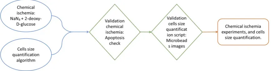
[image:15.595.97.531.411.526.2]Before starting with the chemical ischemia experiments and cell area analysis, we validated both the chemical method chosen and the in-home made algorithm. We started by validating the chemical ischemia protocol, checking that no apoptosis was induced. Then we acquired pictures of some microbeads with known diameter, and applied the size assessment algorithm. In this way we tested the functionality of the algorithm. Following, we proceed with the assessment of cell swelling (Figure 2.1).
Figure 2.1: Flow chart of the study. After choosing the ischemic chemical model and the method for cells size quantification, it was necessary to verify their functionality. The first step was to validate the chemical ischemia method checking that no apoptosis was induced. Following we checked that the implemented script was recognizing the objects and calculating their actual area. To do so we acquired images of microbeads with known size. After the validation experiments were done, we started the chemical ischemia experiments and implemented the script to analyse cells area.
6 CHAPTER2. MATERIALS AND METHODS
2.1 Cell preparation
Cortical neurons, collected on the day of birth from Wistar rats, were used in this study. The cortex was isolated from the brain and sliced in small pieces. Trypsin treatment was applied to help cells detaching from each other. Following, cells were dissociated by trituration and plated on coverslips in 24-well plates. Incubated for 2h using DMEM medium. Subsequently, the DMEM medium was replaced by 500µl of R12 medium. Cells were stored in an incubator under standard conditions (36◦C,
80% humidity, 5% CO2). In addition, in order to maintain the necessary level of nutri-ents in every well, half of the medium was replaced with fresh medium twice a week. The experiments conducted were in accordance with the Dutch law and approved by the Dutch committee on animal use (Project number: AVD110002016802).
In total 38 coverslips were used: eight were used to validate the chemical is-chemia protocol, and thirty for swelling assessment.
2.2 Image acquisition setup
Two different setups were used for images acquisition: One for the validation of the algorithm for cell-size assessment, and one for both the validation of chemical ischemia protocol and for assessment of cell swelling experiments.
2.2.1 Setup to validate the algorithm for cell-size assessment
2.3. ALGORITHM FOR CELL SIZE ASSESSMENT 7
2.2.2 Setup to validate chemical ischemia protocol and for
assess-ment of cell swelling
In all the chemical ischemia experiments, we took fluorescent images of cells. For this purpose, a Nikon inverted microscope supplied with TMD-EF equipment, was used [19]. This set-up utilizes a mercury lamp and a low-pass filter (wave length ≤520nm), exiting the green and red fluorophores used in this study. After adjusting the focus, images were taken automatically at fixed time intervals (every 30s). The automatic acquisition was operated by LabView (National Instruments, Austin, TX), with a fixed number of images acquired and a fixed time interval between the images. Additionally, the camera was controlled by DigiCamControl (Massachusetts Institute of Technology, Boston, MA) software, allowing to set the exposure time and shutter speed. We used a 10x objective lens resulting in a pixel size of 0,19µm. The shutter speed was set to 1/6ms and the exposure time to 1s.
2.3 Algorithm for cell size assessment
8 CHAPTER2. MATERIALS AND METHODS
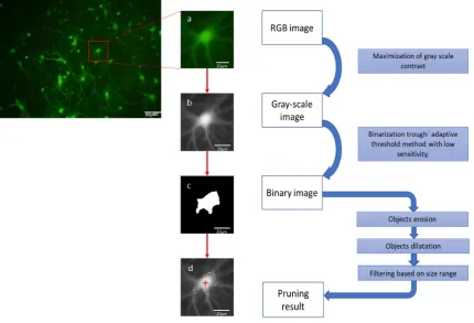
Figure 2.2: Scheme summarizing the main steps followed by the size quantifica-tion algorithm. Loading the fluorescent image (a), transforming it in a grayscale image, applying maximization of the contrast(b), obtaining a binary image (c) by applying the adaptive threshold method. The fi-nal result (d) is obtained after applying morphological operation on the binary image, plus size range-based band-pass filter. The process is applied to all cells, present in the image, at the same time and not at a singular cell level.
RGB to grayscale image. We checked that in the red (R) and blue (B) channels there were no information. Then the RGB image was transformed into a grayscale image (g). To better extract and segment features the grayscale image was
nor-malized. The minimum (ming) and maximum (maxg) value, of the grayscale image
were calculated. These were used for the maximization of the contrast.
M axContrast = (g−ming)×( 255
2.3. ALGORITHM FOR CELL SIZE ASSESSMENT 9
Binary image. Images were binarized by applying the Bradley’s method, as an adaptive threshold filtering. It computes a threshold value for each pixel taking in consideration the local average value of intensity in the surrounding pixels [20]. In addition, to reduce the background noise, it was important to set a value of sensitiv-ity. The sensitivity is a parameter indicating how many, of the lighter pixels, should be considered as foreground objects. Thus, the lower the sensitivity the less noise will be present in the image. The default value given in MATLABis 0,5. Starting from this value we lowered it to various values. These was done because, when set to 0,5, a lot of noise was still taken in account. We also tried to go lower than 0,2, but that brought to the elimination of some relevant objects. For these reasons 0,2 was chosen as the most suitable parameter.
Pruning the binary image. Binary images were pruned using mathematical morphology. To eliminate irrelevant details on cells boundaries, the erosion oper-ation was implemented. It eliminates all the objects smaller than a selected struc-turing element, which in this case was a circle with a radius of 2,5µm [21]. Subse-quently dilatation was utilized to preserve the details on the desired objects using a slightly smaller circle (radius=1,9µm) [21]. An additional filter was then applied. This filter selects only objects with sizes in a specified range (area going from 36,46µm2 to 1444µm2), based on the estimated dimension of cells, determined experimentally from the acquired image [21]. Subsequently, we calculated the number of withe pix-els belonging to each cell and their estimated center of mass.
10 CHAPTER2. MATERIALS AND METHODS
Defining swollen cells. If the area values, collected after the starting of is-chemia, were in ascending order, the cell was considered as a swollen cell. Then, because of the presence of noise, an additional check was needed. We calculated the mean value from the baseline images (all images acquired before chemical is-chemia) and the maximum value obtained during the ten minutes acquisition time. Then we determined the ratio, for all the detected cells. Ratios >1,1 indicated cell swelling, and 100*(Ratio-1) indicated the percentage of increase compared to the baseline. In the end the parameters taken in consideration for the analysis were:
• Total number of recognized cells.
• Number of swollen cells.
• Ratio indicating maximum area increase.
• Time point corresponding to maximum area increase.
• Growing index, defined as ratio between individual cell area and their baseline area at each time point after the ischemia started.
2.4 Chemical ischemia
2.4. CHEMICAL ISCHEMIA 11
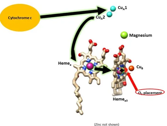
Figure 2.3: Electron transfer from cytochrome c oxidase to oxygen. The electrons pass from the cytochrome c to the two Cua (represented by light blue spheres), then they consequently transfer to the Hemea(purple sphere on the left) and to the Hemea3(purple sphere on the right). In the end, as last passage, the electrons transfer to the oxygen molecule (red sphere) [25].
During anoxic conditions, in presence of glucose, neurons are still able of in-creasing glycolysis, an oxygen-independent metabolic pathway that produces ATP in low amounts [26]. To simulate complete ischemia, it is important to either re-move glucose or use a glycolysis blocker. Based on existing literature analysis, we chose to apply a glycolytic inhibitor, 2-deoxy-D-glucose (2-DG) [4,14]. Therefore, administration of sodium-azide (10mM concentration) and 2-deoxy-D-gluocse (5mM concentration) mimics ischemiain vitro. Chemical ischemia was induced in 3 weeks
12 CHAPTER2. MATERIALS AND METHODS
2.5 Experiments
2.5.1 Validation of chemical ischemia protocol
To verify that the chemical ischemia method used did not induce apoptosis in cells, we used eight coverslips divided in two groups:
• Ischemia group: 4 coverslips containing the cells incubated with sodium-azide and 2-deoxy-D-glucose.
• Control group: 4 coverslips containing the cells incubated with the solvents used to dissolve NaN3and 2-deoxy-D-glucose (water and PBS respectively).
To differentiate between apoptotic and death cells, we added 2 staining solutions: Caspase 3/7 to visualize apoptic cells, and propidium iodide (PI), to visualize dead cells. The Caspase 3/7 is a fluorogenic substrate for activated caspase 3 and 7. In general, the presence of a four amino acid peptide (DEVD) inhibits the possibility of the dye to bind to cells DNA, so the substrate is non fluorescent. However, when apoptosis occurs, the dye is able of giving a green fluorescent response because the DEVD peptide is cleaved. Meanwhile, the PI is a red-fluorescent nuclear and chromosome counterstain. This dye is unable to diffuse into living cells or to cross intact plasma membrane. For this reason, PI is used to stain dead cells.
Once the staining solutions were applied, coverslips were placed under the Nikon inverted microscope to take fluorescent images during 10 minutes (time period in which NaN3 and 2-deoxy-D-glucose were shown to be effective [23]). Images were collected every 30 seconds. The sequence of images was analysed using MATLAB (The Mathworks, Inc., Natick, MA, USA) [27]. The script used is counting the to-tal number of green objects (apoptotic cells), and the number of red objects (dead cells). The number of apoptotic cells was analysed to validate the chemical ischemia protocol.
2.5.2 Validation of algorithm for cell-size assessment
2.5. EXPERIMENTS 13
2.5.3 Assessment of cell swelling
To analyse possible cell swelling induced by chemical ischemia, three groups of experiments were considered:
• Ischemia group: 10 coverslips with cells under chemical ischemia using sodium-azide with 2-deoxy-D-glucose.
• Solvents group: 10 coverslips in which just the solvent of sodium-azide and 2-deoxy-D-glucose (respectively water and PBS) were added to the culture medium.
• Control group: 10 coverslips in normal medium condition.
14 CHAPTER2. MATERIALS AND METHODS
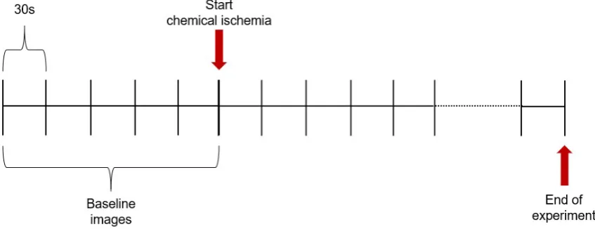
Figure 2.4: Schematic representation of images acquisition. Each line corresponds to a single image. While the space in between the lines is representative of the time interval
2.5.4 Statistical analysis
Chapter 3
Results
3.1 Validation of chemical ischemia protocol
[image:25.595.100.530.527.683.2]The data about the number of apoptotic cells, in both the ischemia and the control group, were not normally distributed. No statistically significant differences were found, among the experiments in each group, (p>0,09). Then, we checked if there were differences between the chemical ischemia group and the control group. No significant differences were found between the two groups (p> 0,25). In Figure 3.1 it is illustrated the trend over the time of the number of apoptotic cells.
Figure 3.1: Apoptosis results. Example of apoptotic cells during ischemia induced with soduim azide and 2-deoxy-D-glucose. The number of apoptotic cells (2), identified by yellow circles, is constant during the 10 minutes of ischemia.
16 CHAPTER3. RESULTS
3.2 Validation of algorithm for cell size assessment
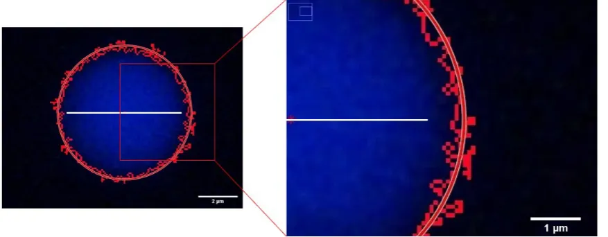
[image:26.595.68.507.243.414.2]The diameters and area data calculated for each image were tested for normal-ity. In both cases, the results obtained per image were normally distributed (p> 0,20). There was no statistically significant difference between the areas calculated from different images (p>0,90). At this point the averages of the beads diameters length and area were calculated (diameter: 6,174µm ± 0,03µm; area: 29,9µm2 ± 0,25µm2).
3.3. ASSESSMENT OF CELL SWELLING 17
3.3 Assessment of cell swelling
3.3.1 Swollen and non-swollen cells
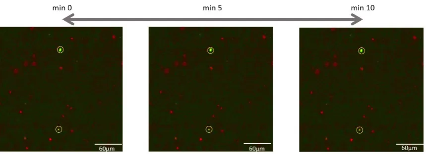
[image:27.595.100.530.251.367.2]In the ischemia group, cells were divided into swollen and non-swollen cells. We checked possible differences between the maximum area ration for swollen and non-swollen cells. The results obtained showed a statistically significant difference between the two groups (Mann-Witney test, p < 0.001). Figure 3.3 is showing an example of swollen cell.
Figure 3.3: Area increase following chemical ischemia. Images corresponding to the beginning of ischemia, the time in which we have the maximum area increase and the end of the 10 minutes incubation (one single swollen cell is taken as example).
18 CHAPTER3. RESULTS
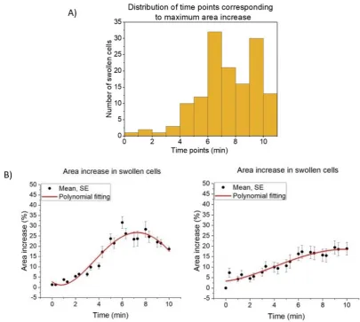
Figure 3.4: Differences in swelling. In panel A the graph is showing how many swollen cells reached their maximum increase in a specific time point. All swollen cells, in the ten experiments, were taken in consideration. In panel B the two graph, obtained from two different experiments, are showing the difference in the area increase trend over the time. In Ap-pendix C it is possible to find graphs corresponding to each experiment.
3.3.2 Group comparison
3.3. ASSESSMENT OF CELL SWELLING 19
Chapter 4
Discussion
In the present study we aimed at analysing more in-depth cell swelling in an in vitro model that mimics ischemic conditions. It is necessary to study mechanisms
leading to necrotic cell death, to understand whether there may be possibilities for future improvements in stroke treatments. This will possibly result in a lower bur-den for stroke survivors, considering that right now the core area is to the center of irreversible brain damage. Of course, there are plenty of difficulties in treating this region, among which the most relevant one is that necrotic death follows within minutes after an ischemic stroke and patients usually don’t make it to the hospital in that time. The mechanism may be more relevant for patients with post-anoxic coma.
The first step is to find a way to quantify cell dimensions. For this reason, we worked on an algorithm to recognize cells and automatically quantify their areas in the x-y plane. Based on previous literature we decided to mimic ischemic stroke conditions chemically using sodium-azide and 2-deoxy-D-glucose. After verifying that this procedure induced no apoptosis, and validating a size quantification script, we observed cell swelling in ∼21% of all cells within 5 to 10 min after the induction of chemical ischemia. The increase in the area was about the 20% of the starting value.
4.1. VALIDATION OF CHEMICAL ISCHEMIA PROTOCOL 21
4.1 Validation of chemical ischemia protocol
One of the main differences between the penumbra and core area in an ischemic stroke is related to the type of cell death [28]. While apoptosis dominates in the penumbra, in the core cells are affected by necrosis [28]. Previous studies have addressed the chosen chemical method, NaN3 together with 2-deoxy-D-glucose, to simulate ischemic stroke in vitro. These two chemicals are capable of simulating
ischemia, thanks to their ability of blocking ATP production and mimic low glucose circumstances [5] [17] [14] [22] [24]. We verified earlier observations that sodium-azide did not induce apoptosis, to ensure that the protocol really simulated core effects [23]. Although most cultures contained a few apoptotic cells, this number did not increase during experiments. Despite the relative low sample size, we saw clearly no difference in the number of apoptotic cells in cultures undergoing chemical ischemia compared to the control group. Thus, we have confidence in concluding that the protocol did not induce undesired penumbra-like effects.
4.2 Validation of algorithm for cell size assessment
The algorithm, implemented to automatically quantify cell dimensions, was validated analysing images of microbeads with known diameter. The obtained results showed that there is an overestimation in the calculated dimaeters and area data compared to the expected ones (repectively error of about 3,5% and 5%). This outcome might be explained by the presence of blur around the edges. Since we are considering three dimensional objects, with rounded borders, when the light is reaching the bor-ders the reflection might cause some blur. Thus, when an image is collected the pixels surrounding the objects edges are slightly lighter than the background. That is why the script is considering them part of the microbeads area (Figure 3.2).
22 CHAPTER4. DISCUSSION
To determine the possible size dependency of overestimation, it will be necessary to use also beads of different sizes. To verify that overestimation in practice induced only minor errors, it would be useful to repeat these experiments with larger beads with green fluorescence. In addition, because of the impossibility of using the same setup adopted for the swelling experiments, further analysis should be done to check possible influences coming from the setup itself. Moreover, it could be, that the blur is also depending, on the fluorescence of the objects, and its response to light. Furthermore, it is important to consider that the parameters adopted, for filtering the objects in the images, are depending on the lens magnification chosen. Thus if the magnification change, the parameters needs to change as well.
4.3 Chemical ischemia effects
4.3. CHEMICAL ISCHEMIA EFFECTS 23
Chemical ischemia is inducing cell swelling, but in two-dimensional images, this was not visible in all cells during the first 10 minutes after the onset of chemical ischemia. In the other cells swelling might have occurred later, but with the experi-mental protocol adopted it was not possible to follow the cultures for more than 10 minutes. This was due to the loss of CO2 and cooling of the cells. The observation that only a fraction of all cells showed swelling might reflect differences in vulnera-bility between cell types. Previous studies already addressed differences in swelling between neurons and glia cells [30] [31] [32] [34] [33] [35] [36]. Some of them sug-gested that, even under anoxic conditions, astrocytes are still swelling more than neurons [34]. This is possibly related to the presence of aquaporins. Furthermore, an interesting finding is that also the time course of swelling differed between cells. This might be related to the different cell type as well. Further analysis needs to be done in order to confirm the real presence of differences in how cells swell (Ap-pendix C).
24 CHAPTER4. DISCUSSION
4.4 Further research
To better understand and analyse cell swelling, it is necessary to differentiate the different cell types. We are currently working on staining neurons and astrocytes in different colours to investigate differences in vulnerability to chemical ischemia. The idea is to apply the AAV2 m-cherry virus (AAV2 AAV-hSyn-hChR2(H134R)-mCherry), which is bringing the mCherry protein to expression, giving a red color to neurons in fluorescence. Until now we weren’t able to acquire images in which both living neurons and astrocytes could be distinguished. It happened that, when the virus is used together with the CellTracker green, the red color is covered by the green. In the image in fact we can only see everything in green. This might be related to the low concentration of the virus used. It will be necessary then to try an higher concentration. Moreover, unfortunately, the inverted microscope adopted is not emitting the necessary excitation wave length required by the mCherry protein. A different setup needs to be used.
Chapter 5
Conclusions
In this study we studied cell swelling under chemical ischemia conditions as occur in the core of a brain infarct. An algorithm was created to quantify changes over time in the area of cells, in the horizontal plane. Under ischemic conditions around ∼21% of all cells showed an increasing area. The area of the swollen cells reached a maximum increase of 20% of their baseline value. However, further studies should assess what happens at the volume level, to determine to what extent changes in the x-y plane are representative of three dimensional volume changes.
Bibliography
[1] S. P. Monteiro, J. Covelo, M. Levers, G. Hassink, J. le Feber, and M. Frega, “Ischemic stroke: Treatments to improve neuronal functional recovery in vitro,” in pHealth 2019: Proceedings of the 16th International Conference on Wear-able Micro and Nano Technologies for Personalized Health 10-12 June 2019, Genoa, Italy, vol. 261, p. 313, IOS Press, 2019.
[2] R. A. Crouch, “Neuroprotection from induced glutamate excitotoxicity by,” chan-nels, vol. 72, no. 4, pp. S15–S48, 2013.
[3] J. Hofmeijer and M. J. van Putten, “Ischemic cerebral damage: an appraisal of synaptic failure,”Stroke, vol. 43, no. 2, pp. 607–615, 2012.
[4] D. Liang, S. Bhatta, V. Gerzanich, and J. M. Simard, “Cytotoxic edema: mecha-nisms of pathological cell swelling,”Neurosurgical focus, vol. 22, no. 5, pp. 1–9,
2007.
[5] E. Bandera, M. Botteri, C. Minelli, A. Sutton, K. R. Abrams, and N. Latronico, “Cerebral blood flow threshold of ischemic penumbra and infarct core in acute ischemic stroke: a systematic review,” Stroke, vol. 37, no. 5, pp. 1334–1339,
2006.
[6] A. M. Kaufmann, A. D. Firlik, M. B. Fukui, L. R. Wechsler, C. A. Jungries, and H. Yonas, “Ischemic core and penumbra in human stroke,”Stroke, vol. 30, no. 1,
pp. 93–99, 1999.
[7] T. L. Rothstein, “The role of evoked potentials in anoxic–ischemic coma and se-vere brain trauma,”Journal of Clinical Neurophysiology, vol. 17, no. 5, pp. 486–
497, 2000.
[8] B. C. Campbell, C. B. Majoie, G. W. Albers, B. K. Menon, N. Yassi, G. Sharma, W. H. van Zwam, R. J. van Oostenbrugge, A. M. Demchuk, F. Guillemin, et al.,
“Penumbral imaging and functional outcome in patients with anterior circula-tion ischaemic stroke treated with endovascular thrombectomy versus medical therapy: a meta-analysis of individual patient-level data,” The Lancet Neurol-ogy, vol. 18, no. 1, pp. 46–55, 2019.
28 BIBLIOGRAPHY
[9] O. A. Berkhemer, P. S. Fransen, D. Beumer, L. A. van den Berg, H. F. Lingsma, A. J. Yoo, W. J. Schonewille, J. A. Vos, P. J. Nederkoorn, M. J. Wermer, et al.,
“A randomized trial of intraarterial treatment for acute ischemic stroke,” New England Journal of Medicine, vol. 372, no. 1, pp. 11–20, 2015.
[10] S. P. Kloska, M. Wintermark, T. Engelhorn, and J. B. Fiebach, “Acute stroke magnetic resonance imaging: current status and future perspective,” Neurora-diology, vol. 52, no. 3, pp. 189–201, 2010.
[11] K. M. Busl and D. M. Greer, “Hypoxic-ischemic brain injury: pathophysiology, neuropathology and mechanisms,” NeuroRehabilitation, vol. 26, no. 1, pp. 5–
13, 2010.
[12] R. L. Rungta, H. B. Choi, J. R. Tyson, A. Malik, L. Dissing-Olesen, P. J. Lin, S. M. Cain, P. R. Cullis, T. P. Snutch, and B. A. MacVicar, “The cellular mechanisms of neuronal swelling underlying cytotoxic edema,”Cell, vol. 161, no. 3, pp. 610–
621, 2015.
[13] K. Dijkstra, J. Hofmeijer, S. A. van Gils, and M. J. van Putten, “A biophysi-cal model for cytotoxic cell swelling,” Journal of neuroscience, vol. 36, no. 47,
pp. 11881–11890, 2016.
[14] H. Cimarosti and J. M. Henley, “Investigating the mechanisms underlying neu-ronal death in ischemia using in vitro oxygen-glucose deprivation: potential involvement of protein sumoylation,”The Neuroscientist, vol. 14, no. 6, pp. 626–
636, 2008.
[15] B.-M. Mackert, F. Staub, J. Peters, A. Baethmann, and O. Kempski, “Anoxia in vitro does not induce neuronal swelling or death,” Journal of the neurological sciences, vol. 139, no. 1, pp. 39–47, 1996.
[16] G. E. Lang, P. S. Stewart, D. Vella, S. L. Waters, and A. Goriely, “Is the donnan effect sufficient to explain swelling in brain tissue slices?,”Journal of The Royal Society Interface, vol. 11, no. 96, p. 20140123, 2014.
[17] P. M. Holloway and F. N. Gavins, “Modeling ischemic stroke in vitro: status quo and future perspectives,”Stroke, vol. 47, no. 2, pp. 561–569, 2016.
[18] E. i. Instructions, “” nikon microscope, eclipse 50i eclipse 55i,”
[19] E.-F. ATTACHMENT, “” tmd-ef,”
BIBLIOGRAPHY 29
[21] J. Pang, N. ¨Ozkucur, M. Ren, D. L. Kaplan, M. Levin, and E. L. Miller, “Automatic neuron segmentation and neural network analysis method for phase contrast microscopy images,”Biomedical optics express, vol. 6, no. 11, pp. 4395–4416,
2015.
[22] M. Chen and J. M. Simard, “Cell swelling and a nonselective cation channel regulated by internal ca2+ and atp in native reactive astrocytes from adult rat brain,”Journal of Neuroscience, vol. 21, no. 17, pp. 6512–6521, 2001.
[23] R. Selvatici, M. Previati, S. Marino, L. Marani, S. Falzarano, I. Lanzoni, and A. Siniscalchi, “Sodium azide induced neuronal damage in vitro: evidence for non-apoptotic cell death,”Neurochemical research, vol. 34, no. 5, pp. 909–916,
2009.
[24] J. Harvey, S. Hardy, and M. Ashford, “Dual actions of the metabolic inhibitor, sodium azide on katp channel currents in the rat cri-g1 insulinoma cell line,”
British journal of pharmacology, vol. 126, no. 1, pp. 51–60, 1999.
[25] A. Slusser, “Cytochrome oxidases.”
[26] N. Koschmieder Jørgensen, S. F. Petersen, I. Damgaard, A. Schousboe, and E. K. Hoffmann, “Increases in [ca2+] i and changes in intracellular ph during chemical anoxia in mouse neocortical neurons in primary culture,” Journal of neuroscience research, vol. 56, no. 4, pp. 358–370, 1999.
[27] D. T. di Bordonia, “Prolonged inactivity is associated with neuronal apoptosis: activation may improve recovery,” 2019.
[28] B. Puig, S. Brenna, and T. Magnus, “Molecular communication of a dying neu-ron in stroke,”International journal of molecular sciences, vol. 19, no. 9, p. 2834,
2018.
[29] K. Takata, T. Matsuzaki, and Y. Tajika, “Aquaporins: water channel proteins of the cell membrane,” Progress in histochemistry and cytochemistry, vol. 39,
no. 1, pp. 1–83, 2004.
[30] R. D. Andrew, M. W. Labron, S. E. Boehnke, L. Carnduff, and S. A. Kirov, “Physi-ological evidence that pyramidal neurons lack functional water channels,” Cere-bral Cortex, vol. 17, no. 4, pp. 787–802, 2006.
30 BIBLIOGRAPHY
[32] F. Sachs and M. V. Sivaselvan, “Cell volume control in three dimensions: Wa-ter movement without solute movement,” The Journal of general physiology,
vol. 145, no. 5, pp. 373–380, 2015.
[33] Y. Chen and R. A. Swanson, “Astrocytes and brain injury,” Journal of Cerebral Blood Flow & Metabolism, vol. 23, no. 2, pp. 137–149, 2003.
[34] N. H¨ubel and G. Ullah, “Anions govern cell volume: a case study of relative astrocytic and neuronal swelling in spreading depolarization,”PloS one, vol. 11,
no. 3, p. e0147060, 2016.
[35] T. Takano, G.-F. Tian, W. Peng, N. Lou, D. Lovatt, A. J. Hansen, K. A. Kasischke, and M. Nedergaard, “Cortical spreading depression causes and coincides with tissue hypoxia,”Nature neuroscience, vol. 10, no. 6, p. 754, 2007.
[36] C. Petito, W. Pulsinelli, G. Jacobson, and F. Plum, “Edema and vascular perme-ability in cerebral ischemia: comparison between ischemic neuronal damage and infarction,” Journal of Neuropathology & Experimental Neurology, vol. 41,
Appendix A
Appendix A
A.1 Algorithm: M
ATLAB
script
The first step is to transform the RGB image (I) in grayscale image (g).
On the grayscale image, we applied the normalization of the data, trough the maxi-mization of the contrast.
32 APPENDIXA. APPENDIX A
Following we transformed the grayscale image in a binary image. This was done by the application of the adaptive threshold filter, for which sensitivity is an impor-tant parameter. In addition we applied two morphological operations in order to not consider irrelevant objects (erosion and dilatation).
Because of the presence of additional noise in the background, one more filter was applied based on size range.
Then we found the edges and plot them on the grayscale image.
Appendix B
Appendix B
B.1 Stock solutions
Sodium-azide preparation:
1. We weighted 62.2 mg of sodium-azide in a 1ml plastic, sterile, tube under the flow hood.
2. We calculated the amount of water needed in order to have a solution 0.5M.
• We went under the flow hood again and I inserted 5ml of water in a 10ml sterile tube.
• From that tube We took 0.957 ml and put them into the 1ml tube contain-ing the sodium-azide powder.
• Then We rinsed a bit inside the 1ml tube until the sodium-azide powder was completely diluted.
3. At the end, after cleaning the flow hood, the stock solution was stored in the fridge and the remaining sodium-azide placed back in the storage box.
2-deoxy-D-glucose preparation:
1. 4mg of 2-deoxyglucose were weighted in a 1ml tube.
2. Then we took 0.05ml of PBS and put them into the tube to dissolve the powder, resuspending few times.
3. Once the solution was ready it was placed back in the fridge.
34 APPENDIX B. APPENDIX B
CellTracker Green preparation:
1. Take the 50ug tube with the cell tracker out of the freezer and let it defrost for few minutes. Also take the DMSO box out of the cabinet
2. Then put the cell tracker tube and the DMSO under the flow hood.
3. At this point take 107,6ul of DMSO and put them in the cell trackers tube to create a 1mM solution.
Appendix C
Appendix C
C.1 Chemical ischemia results: Ischemia group.
C.1.1 experiment 1
Date 04−10−2019
Age 15 days
[image:45.595.94.509.293.645.2]Total number of cells 105 Number of swollen cells 21 Averaged area increase 14,3%
Figure C.1: On the left, average of area increase following chemical ischemia, at each time point. The graph is representing the trend of the area cal-culated on swollen cells. On the right, representation of time point in which each swollen cell reaches its maximum area increase.
36 APPENDIX C. APPENDIX C
C.1.2 experiment 2
Date 08−10−2019
Age 19 days
[image:46.595.70.484.89.402.2]Total number of cells 69 Number of swollen cells 8 Averaged area increase 15%
C.1. CHEMICAL ISCHEMIA RESULTS: ISCHEMIA GROUP. 37
C.1.3 experiment 3
Date 10−10−2019
Age 21 days
[image:47.595.92.522.88.408.2]Total number of cells 197 Number of swollen cells 59 Averaged area increase 29,9%
38 APPENDIX C. APPENDIX C
C.1.4 experiment 4
Date 11−10−2019
Age 22 days
[image:48.595.68.481.87.399.2]Total number of cells 68 Number of swollen cells 10 Averaged area increase 41%
C.1. CHEMICAL ISCHEMIA RESULTS: ISCHEMIA GROUP. 39
C.1.5 experiment 5
Date 16−10−2019
Age 27 days
[image:49.595.94.509.87.405.2]Total number of cells 75 Number of swollen cells 28 Averaged area increase 32%
40 APPENDIX C. APPENDIX C
C.1.6 experiment 6
Date 16−10−2019
Age 27 days
[image:50.595.64.479.85.401.2]Total number of cells 65 Number of swollen cells 10 Averaged area increase 17,2%
C.1. CHEMICAL ISCHEMIA RESULTS: ISCHEMIA GROUP. 41
C.1.7 experiment 7
Date 17−10−2019
Age 14 days
[image:51.595.96.511.84.406.2]Total number of cells 148 Number of swollen cells 26 Averaged area increase 24,3%
42 APPENDIX C. APPENDIX C
C.1.8 experiment 8
Date 18−10−2019
Age 15 days
[image:52.595.64.489.91.401.2]Total number of cells 81 Number of swollen cells 26 Averaged area increase 15,3%
C.1. CHEMICAL ISCHEMIA RESULTS: ISCHEMIA GROUP. 43
C.1.9 experiment 9
Date 01−11−2019
Age 15 days
[image:53.595.92.515.84.408.2]Total number of cells 79 Number of swollen cells 19 Averaged area increase 23,8%
44 APPENDIX C. APPENDIX C
C.1.10 experiment 10
Date 03−11−2019
Age 17 days
[image:54.595.60.488.87.404.2]Total number of cells 113 Number of swollen cells 16 Averaged area increase 16,5%
![Figure 1.1: Representation of ischemic stroke [10]](https://thumb-us.123doks.com/thumbv2/123dok_us/9630472.465542/12.595.138.433.226.399/figure-representation-of-ischemic-stroke.webp)
![Figure 1.2: Mechanisms inducing cell swelling [12]](https://thumb-us.123doks.com/thumbv2/123dok_us/9630472.465542/13.595.178.450.91.354/figure-mechanisms-inducing-cell-swelling.webp)