warwick.ac.uk/lib-publications
Original citation:
Shreejith, Shanker and Fahmy, Suhaib A.. (2015) Extensible FlexRay communication
controller for FPGA-based automotive systems. IEEE Transactions on Vehicular Technology,
64 (2). pp. 453-465.
Permanent WRAP URL:
http://wrap.warwick.ac.uk/86742
Copyright and reuse:
The Warwick Research Archive Portal (WRAP) makes this work by researchers of the
University of Warwick available open access under the following conditions. Copyright ©
and all moral rights to the version of the paper presented here belong to the individual
author(s) and/or other copyright owners. To the extent reasonable and practicable the
material made available in WRAP has been checked for eligibility before being made
available.
Copies of full items can be used for personal research or study, educational, or not-for profit
purposes without prior permission or charge. Provided that the authors, title and full
bibliographic details are credited, a hyperlink and/or URL is given for the original metadata
page and the content is not changed in any way.
Publisher’s statement:
© 2015 IEEE. Personal use of this material is permitted. Permission from IEEE must be
obtained for all other uses, in any current or future media, including reprinting
/republishing this material for advertising or promotional purposes, creating new collective
works, for resale or redistribution to servers or lists, or reuse of any copyrighted component
of this work in other works.
A note on versions:
The version presented here may differ from the published version or, version of record, if
you wish to cite this item you are advised to consult the publisher’s version. Please see the
‘permanent WRAP url’ above for details on accessing the published version and note that
access may require a subscription.
Extensible FlexRay Communication Controller
for FPGA-Based Automotive Systems
Shanker Shreejith
Student Member, IEEE
and Suhaib A. Fahmy
Senior Member, IEEE
Abstract—Modern vehicles incorporate an increasing number of distributed compute nodes, resulting in the need for faster and more reliable in-vehicle networks. Time-triggered protocols like FlexRay have been gaining ground as the standard for high-speed reliable communication in the automotive industry, marking a shift away from the event-triggered medium access used in Controller Area Networks (CAN). These new standards enable the higher levels of determinism and reliability demanded by next generation safety critical applications. Advanced applications can benefit from tight coupling of the embedded computing units with the communication interface, thereby providing functionality beyond the FlexRay standard. Such an approach is highly suited to implementation on reconfigurable architectures.
This paper describes an FPGA-based communication con-troller which features configurable extensions to provide func-tionality that is unavailable with standard implementations or off the shelf devices. It is implemented and verified on a Xilinx Spartan 6 FPGA, integrated with both a logic-based hardware ECU and a fully fledged processor-based ECU. Results show that the platform-centric implementation generates a highly efficient core in terms of power, performance and resource utilisation. We demonstrate that the flexible extensions help enable advanced applications that integrate features like fault-tolerance, timeliness and security, with practical case studies. This tight integration between the controller, computational functions and flexible extensions on the controller enables enhancements that open the door for exciting applications in future vehicles.
Index Terms—Field programmable gate arrays; automotive systems; networks.
I. INTRODUCTION
Modern high-end vehicles incorporate one hundred or more embedded computing units which implement advanced capa-bilities like auto-park, pedestrian detection with auto-brake and other safety or comfort features. These algorithms perform complex processing on data gathered from a network of sensors, to produce control sequences for distributed actua-tors. The communication bandwidth and quality of service required for such advanced electronic control units (ECUs) exceeds the capabilities of the event-triggered Controller Area Network (CAN) protocol, that has been pervasive in au-tomotive systems until now. Moreover, next generation in-vehicle systems, specifically in electric in-vehicles that have a high level of automation, demand higher determinism, leading
Copyright (c) 2013 IEEE. Personal use of this material is permitted. However, permission to use this material for any other purposes must be obtained from the IEEE by sending a request to [email protected]. S. Shreejith is with the School of Computer Engineering, Nanyang Tech-nological University and TUM CREATE, Singapore
S. A. Fahmy is with the School of Computer Engineering, Nanyang Technological University, Singapore
e-mail:{shreejit1, sfahmy}@ntu.edu.sg Manuscript received ; revised
to the widespread adoption of time-triggered communication schemes and protocols like FlexRay and time-triggered Eth-ernet [1]. FlexRay is gaining ground as a de-facto commu-nication standard for safety-critical functions like drive-by-wire, cruise control and adaptive braking systems, while also facilitating communication for non-critical ECUs.
Though time-triggered networks like FlexRay provide higher determinism and communication bandwidth, increas-ing proliferation of embedded computincreas-ing units increases the associated communication overheads and power consumption, which can degrade overall system performance. Typically, each ECU has a discrete communication controller to manage its access to the network. We show that by closely coupling the controller with the ECU and extending the predefined communication framework, advanced and intelligent embed-ded compute units with enhanced capabilities like fall-back and fault-tolerance can be designed. This scheme enhances the overall quality and performance of the system. However, such evolutions and extensions of the protocol cannot be im-plemented using off-the-shelf controllers or platform agnostic solutions, and require a modular flexible implementation, that is ideally implemented in reconfigurable logic. Moreover, re-configurable technology enables us to merge the controller and multiple applications on the same device, while preserving the necessary isolation between them, and partial reconfigurability can be exploited to reduce power consumption further [2].
In this paper, we present an architecture-optimised FlexRay communication controller (CC) which integrates configurable extensions that augment the CC’s capabilities beyond those defined by the FlexRay standard. The controller provides enhancements to the datapath, like programmable width time-stamping, data filtering, header insertion and processing func-tions, which are abstracted away from the host function. Our flexible architecture can be used to design advanced ECUs on reconfigurable hardware, that consume less power and offer increased consolidation, while providing enhanced capabilities that are impossible to implement using standard controllers or IP cores. We also quantify the potential of the proposed controller using case studies based on existing and evolving automotive applications that are safety-critical and data-intensive. Our experiments show that advanced features like high-speed mode switching for fault-tolerant ECUs, low-latency data handling for high performance gateways, time-liness and security for messages can be efficiently achieved by integrating such extensions within the controller datapath, rather than offloading them to the processing logic.
speci-fication and protocol enhancements described in the literature, and related work in this area. Section III details the controller architecture. Implementation results and comparison to other implementations are provided in Section IV. In Section V, we present case studies using the customisable extensions, and show the benefits of implementing advanced features this way, with a discussion of the approach in Section VI. Finally, we conclude the paper and outline future work in Section VII.
II. RELATEDWORK
The move towards time-triggered network standards in automotive systems has been driven by the more advanced requirements imposed by advanced mission-critical and com-fort features in future vehicles. Widespread event triggered networks like CAN (controller area network) fail to address the requirements of such applications.
TT-CAN is an extension of the CAN protocol that enables time-triggered operation by enforcing a slot-based structure, while retaining backwards compatibility with standard CAN. However, TT-CAN suffers from dependability issues and lim-ited bandwidth, and thus it did not gain widespread adoption. Some research sought to overcome these limitations through hardware extensions on the network controller [3].
In recent years, FlexRay has emerged as the standard for time-triggered communication in the automotive domain. However, most recently, new hardware developments have seen time-triggered Ethernet emerge as a possible replacement for FlexRay, though standard communication protocols are still under development. The enhancements we present in this paper can be similarly applied to other time-triggered standards, though we use FlexRay to demonstrate the concepts within a realistic, certifiable environment.
A. The FlexRay Protocol
The FlexRay protocol is developed and standardised by the FlexRay consortium, and has since been adopted by various automotive companies in production vehicles [4]. These ve-hicles are complaint with the FlexRay AUTOSAR Interface Specification Standard [5], which is the industry standard for the software specification of FlexRay nodes, by which any controller implementation must comply.
The fundamental element of the media access scheme in the FlexRay protocol is the communication cycle, which is repeated over time, as shown in Fig. 1. Each cycle is comprised of four segments [6]:
• The Static Segmentwhich uses a static slot-based access
mechanism and is used to send critical data in a deter-ministic manner. Any ECU can send a frame of data in the one (or more) slot(s) assigned to it. The slot width is fixed across all nodes on the network.
• The Dynamic Segment which uses a dynamic slot-based access scheme enabling communication of event triggered data of arbitrary length. The slot width is dynamic, depending on the amount of data that needs to be transmitted, and access to the medium is controlled by priorities assigned to the ECUs.
Cycle 0 Cycle 1 ... Cycle 63
Static Segment Dynamic Segment Symbol Window NIT
[image:3.612.316.563.51.150.2]Slot 1 Slot 2 ... Slot n Slot 1 Slot 2 ... Slot k
Fig. 1: The FlexRay communication cycle.
A 1 A 2
B 1
B 2
C 1 C 2
D 1 D 2
(a) Active Star
A 1 A 2
B 1
B 2
C 1 C 2
D 1 D 2
(b) Switch
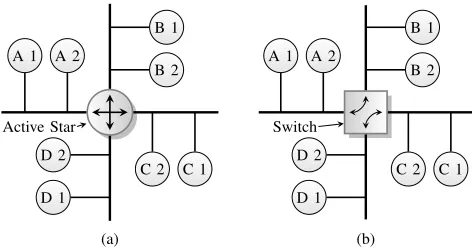
Fig. 2: A standard (a) and switched (b) FlexRay network topology.
• The Symbol Window which is used to transmit special symbols like the “wake-up” pattern used to wake-up sleepingnodes to initiate communication.
• Network Idle Timewhich is the idle period used by nodes to make clock adjustments and align and correct the global view of time to maintain synchronisation. A typical FlexRay-based ECU integrates a discrete (or embedded) Communication Controller (CC) and the compu-tational function, which is usually implemented as a software algorithm on a processor to provide flexibility and upgradabil-ity. The ECU can communicate over the bus, through the CC, by transmitting framed data in the slot(s) assigned to it in the static or dynamic segments.
Multiple nodes may share the same slot in different cycles, as in the case of odd/even cycle multiplexing where one set of nodes is assigned slots in all odd cycles whereas another set of nodes (which may include some from the first set) is assigned slots in all even cycles. This scheme of cycle-level slot multiplexing can lead to higher overall bandwidth utilisation. Fig. 2(a) shows a typical network setup, where node
B2may send data to nodeA1 in slot 1 of cycle 1 while node
A1may reply in slot 1 of cycle 2. Theactive staris an active repeater that passes information from one branch to all other branches.
[image:3.612.321.557.185.309.2]as shown in Fig. 2(b), while node B2 may be sending data to node A1 in slot 1 of cycle 1, node D1 might be sending data to nodeC2in the same slot and the switch, knowing the schedule, connects the corresponding nodes through the switch fabric. Utilising slot multiplexing and branch parallelism, each slot within a cycle may have different destinations and thus different switch configurations.
Research on FlexRay networks has been approached from diverse directions in the literature. In [10], the authors high-light challenges like physical-layer design, cycle and schedule design, and selection of termination, sync and startup nodes which were all simpler design considerations for FlexRay’s predecessor, CAN.
B. Scheduling
Much work has been done on scheduling communication on the shared bus. Optimisation of the static and dynamic segment of the FlexRay protocol has been widely addressed in [11], [12] and [13], [14], [15], among others. [16] presents a detailed survey of scheduling algorithms and provides a comparison be-tween optimisation strategies like simulated annealing, genetic, hybrid-genetic and probabilistic approaches applied by various algorithms. Given a set of communication requirements, all algorithms try to optimise the number of communication slots and cycles that are required to schedule the different messages, satisfying all requirements. The optimisation in most cases is to find the minimum number of communication slots that can solve the problem, hence consuming minimum bandwidth. Alternatively, the problem can be formulated to maximise the number of unused slots, which provides flexibility for future expansion.
C. Network Level Optimisations
The work in [17] discusses an approach to improve the energy efficiency of a FlexRay controller by allowing it to be controlled by an intelligent communication controller (ICC). The ICC, which takes over bus operations from the ECU when the latter goes to sleep, prevents the ECU from being woken by erroneous transmissions allowing the node to achieve higher power efficiency. The proposed architecture and its validation are also discussed in the paper, using a proprietary implementation of the FlexRay communication controller that is not available to the research community. Similarly, the work in [18] describes the architecture of an FPGA-implementation of the FlexRay controller with add-on features to aid functiadd-onal verificatiadd-on. The features are primarily aimed at a verification framework and hence do not point in the direction of optimisations or enhancements for improving node/network functionality beyond standard implementations.
D. Controller Implementation
[19] is the only work to discuss the implementation of a FlexRay communication controller on reconfigurable logic. The work discusses the protocol operations control mod-ule, which controls the actions of the core modules of the
communication controller. However, no specific details about hardware architecture are presented, and the implementation is designed purely to implement the existing specification, with no new features. [20], [21] also describe implementation of the FlexRay Communication Controller using the specification and description language (SDL) as the platform and later translation to hardware using Verilog. Their work approaches the protocol from a high level of abstraction and hence does not discuss hardware design details or architectural optimisa-tions. A comprehensive outline of the FlexRay Bus Guardian specification and approaches to implement it on FPGAs have also been discussed in [22], [23].
Bosch and Freescale both offer implementations of the FlexRay controller that can be mapped to a wide range of platforms [24], [25]. These are largely platform independent, suitable for implementing on ASICs or FPGAs. However, they are not optimal for implementation on reconfigurable hardware, since they do not fully utilise the heterogeneous resources available in the fabric. For instance, the E-Ray IP core from Bosch, which is a dual channel controller, does not directly instantiate FPGA primitives like DSP Blocks or Block RAMs but uses general purpose logic to implement these functions.
By efficiently utilising these hardware primitives, we can build custom controllers which are more efficient for archi-tecture specific implementations, while leaving aside logic for implementing functional components of the ECU. This approach results in limited portability between platforms, but superior utilisation and power efficiency for FPGA-based ECU implementations. Portability is also becoming less of an issue as FPGA manufacturers standardise hardware blocks across all their device families in a given generation. For example, the DSP48E1 primitive is available on all 7-series FPGAs from Xilinx, as well as the Zynq ARM-FPGA platform.
We aim, through our work, to enable a number of investiga-tions in the space of FlexRay on reconfigurable hardware. We focus on providing a flexible communication controller which features rich extensions for enhanced applications, architecture optimisations for low device utilisation, providing considerable savings in terms of area and power. The objective is to show how an FPGA-centric implementation can result in interfaces that provide advanced capabilities and power efficiency for FPGA-based in-vehicle systems.
III. ARCHITECTUREDESIGN
FlexRay CC
Controller Host Interface
PLB/AXI Interface
Control, Status &Configuration
Data Store (Tx/Rx)
Protocol Engine
PMM CS
MIL Channel A
MIL Channel B CHI Bus
PE Bus
Tx En Tx D
Rx D Rx DTx DTx En
FlexRay Bus Driver Channel A
[image:5.612.73.277.55.275.2]FlexRay Bus Driver Channel B To Host
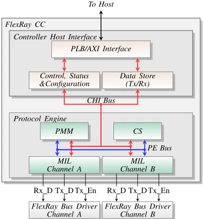
Fig. 3: Architecture of custom Flexray communication controller.
Communication Controller and Bus Driver independently and configures them appropriately at startup or during runtime.
A. Communication Controller
The FlexRay CC switches between different operating states, based on network conditions and/or host commands, ensuring conditions defined by the FlexRay protocol are met at all times. The CC architecture, as shown in Fig. 3, comprises the Protocol Engine (PE) which implements the protocol behaviour, and the Controller Host Interface (CHI) which interfaces to the host ECU.
The CHI module communicates with the host and handles commands and configuration parameters for the FlexRay node. These parameters are defined for the particular cluster the node is operating on, and are initialised during the node’s configuration phase. The CHI feeds the current state and operational status to the host for corrective action if necessary. There are transmit and receive buffers and status registers for the data-path to isolate control and data flow. The CHI may also incorporate clock domain crossing circuitry to enable the different interfaces to work in distinct clock domains.
The Clock Synchronisation (CS) and Medium Interface Layers (MIL) submodules of the Protocol Engine implement specific functions of the protocol, which are controlled and coordinated by the Protocol Management Module (PMM). These sub-modules support multiple modes of operation and can alter their current operating mode in response to changes in any of the parameters, error conditions, or host commands. The PMM ensures mode changes are done in a way that complies with the FlexRay specifications. The Medium Interface Layer handles the transmission and reception of data over the shared bus. It encodes and decodes data, controls medium access and processes decoded data to ensure adherence to protocol specifications. The CS module generates the local node-clock, synchronised to the global view of time. It measures deviation
in the node clock on a per-cycle basis so that it stays synchronised with other nodes in the cluster.
Timing in a FlexRay node is defined in macroticks and microticks. Microticks measure the granularity of the node’s local internal time and are derived from the internal clock of a node. A macrotick is composed of an integer number of microticks. The duration of each local macrotick should be equal within all nodes in the cluster. The FlexRay protocol uses a distributed clock correction mechanism, whereby each node individually adjusts its view of time by observing the timing information transmitted by other nodes. The adjustment value is computed using a fault-tolerant midpoint algorithm. A combination of rate (frequency) and offset (phase) correction mechanisms are used to synchronise the global time view of different nodes. These corrections must be applied in the same way at all nodes and must fulfil the following conditions:
1) Rate correction is continuously applied over the entire cycle.
2) Offset correction is applied only during the NIT in an odd cycle and must finish before the start of the next communication cycle.
3) Rate correction is computed once per double cycle, following the static segment in an odd cycle. The calculation is based on values measured in an even-odd double cycle.
4) Calculation of offset correction takes place every cycle, but is applied only at the end of odd cycle.
Rate correction indicates the number of microticks that need to be added to the configured number of microticks per cycle and may be negative, indicating that the cycles should be shorter. Offset corrections indicates the number of microticks that need to be added to the offset segment of the network idle time and may also be negative.
The FlexRay bus supports two independent channels for data transmission and reception. The transmission rate can be set at 2.5 Mbps, 5 Mbps or 10 Mbps. The protocol also defines multiple bus access mechanisms, in the form of static slots for synchronous time-triggered communication and dynamic slots for burst mode event-triggered (priority-based) data transfer. Special symbols can be transmitted within thesymbol window, like wake-up during operation (WUDOP) and collision avoidance symbols (CAS). During the network interval time, all nodes synchronise their clock view with the global clock view so that they stay synchronous. Each trans-mitted bit is represented using 8 bit-times to ensure protection from interference. At the receiving end, these are sampled and majority voted to generate a voted bit. Transmission and reception must be confined to slot-boundaries and transmission (or reception) across slot-boundaries is marked as a violation. The node should transmit only on slots that are assigned to it (either in the static or dynamic segments). Each node is assigned a keyslot, which it uses to transmit startup or synchronisation frames (along-with data).
B. Implementation and Optimisations of Custom CC
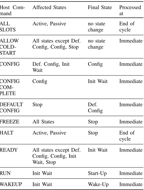
TABLE I: Commands from Host that affect CC Operating Modes.
Host Com-mand
Affected States Final State Processed at
ALL SLOTS
Active, Passive no state change
End of cycle
ALLOW COLD-START
All states except Def. Config, Config, Stop
no state change
Immediate
CONFIG Def. Config, Init Wait
Config Immediate
CONFIG COM-PLETE
Config Init Wait Immediate
DEFAULT CONFIG
Stop Def.
Config
Immediate
FREEZE All States Stop Immediate
HALT Active, Passive Stop End of cycle
READY All states except Def. Config, Config, Init Wait, Stop
Init Wait Immediate
RUN Init Wait Start-Up Immediate
WAKEUP Init Wait Wake-Up Immediate
changes in the CC and MIL submodules, and describes the different operating modes of the node, as depicted in Fig. 4. These mode changes can be triggered by host commands or by internal and/or network conditions encountered by the node. Table I describes the different commands issued by the host and how the operation of the CC is modified in response. As can be seen, certain commands demand an immediate response from the controller, while others are to be applied at specific points within the communication cycle. This distinction makes the control flow more complex than the case of a straight-forward finite state machine (FSM).
The FlexRay protocol allows a cluster and its associated nodes to switch to sleep mode to conserve power. When any node needs to start communication on the network, a wakeup sequence is triggered by the host by putting the CC into wakeup state. In the wakeup state, the node tries to awaken a sleeping network by transmitting a wake-up-pattern (WUP) on one channel. Sleeping nodes decode this pattern and trigger a node wakeup. Nodes which have dual channel capability then trigger a wakeup on the other channel to complete a cluster-wide wakeup. The node cannot, however, verify the wakeup trigger at all connected nodes, since WUP has no mechanism to communicate the ID of the nodes that have responded. The nodes then follow the startup procedure to initialise communication on the cluster. The startup operation also caters for re-integration of a node onto an active network. To do so, the node must start its local clock so that it is
Def. Config
Config
Init
Wait Wakeup
Startup Active Passive
Stop *
Config Command
Config
Done CommandConfig Wakeup Command
Wakeup complete Ready Command
Run Command
Integration Success Ready
Command Sync
Error
Sync Ok Halt Command or Critical Error
Freeze Command
Fig. 4: Flexray CC Modes of Operation.
Protocol Management
uCode ROM
Wake Up
PMM Main
Start
Up Shared Resources Addr
Gen Host Commands
Node-Network Conditions
Control Signals PE in
CHI in
Sys Clk
Sys Rst
PE out
CHI out
Fig. 5: Protocol Management module architecture.
synchronised with the network time.
[image:6.612.57.294.81.392.2]Clock Sync
CSP SM
MTG
CSS SM uT Timer
MT Timer
((A−B)∗C+D)%E CAM EVEN
Channel A Slot ID & Deviation
Channel B Slot ID & Deviation CAM ODD
Channel A Slot ID & Deviation
Channel B Slot ID & Deviation
A B C D E Port A
Port B Port A
Port B
PE in
CHI in
Sys Clk Sys Rst
uT Clk MT Clk
PE out
[image:7.612.57.301.52.217.2]CHI out
Fig. 6: Clock Sync module architecture.
In our design, the PMM also encapsulates Wakeup and Startup. Combining the operations of WUP and SUP with the operations at each state of PMM results in a hierarchical structure, as in Fig. 5, with the combined state encodings stored in the microcoded ROM. Combining the two functions into the same module also allow us to share resources between the two operations, which are not required concurrently, using simplified control flow. Since CS and MIL are also controlled by WUP and SUP for the associated wake-up and start-up operations, integrating them with the PMM results in centralised control for all operating conditions, simplifying interfaces to the submodules. The responses to different con-ditions or stimuli is now reduced to the process of generating appropriate addresses for the ROM, similar to the program counter implementation on a standard processor. The ROM is efficiently implemented using distributed memory (LUTs) because of its small size.
Fig. 6 shows a simplified architecture of the CS module in our design. The CS module generates the clock, computes the deviations of the generated clock from the distributed timing information and applies corrections. The CS module is comprised of 2 concurrent operations (or submodules): firstly, the MTG process which controls the cycle counter and the macrotick counters and applies the rate/frequency and offset/phase correction values; and secondly, the Clock Synchronisation Process (CSP) that performs the initialisation at cycle start, the measurement and storage of deviation values during the cycle and computes the offset and rate correction values. In addition, the CSS module is responsible for starting a synchronous clock when the CC tries to integrate into either an active network or initiate communication on an idle network. The CSP state machine controls and co-ordinates the operations of the CS module by interacting with the CSS and MTG submodules.
During Startup, the CSS process monitors the arrival time of the even synchronisation frames and generates the global reference time by computing the initial Macrotick value as
Macrotick = (pMacroInitialOffset+gdStaticSlot
×(ID−1)) modgMacroPerCycle,
Stat. Dyn. Sym. NIT Stat. Dyn. Sym. NIT Stat. Dyn. Sym. NIT
even cycle (2n) odd cycle (2n+1) even cycle (2n+2) optional
rate correction rate correction rate correction
MTG
measure O measure O R
CSP
compute compute
[image:7.612.313.564.59.166.2]offset
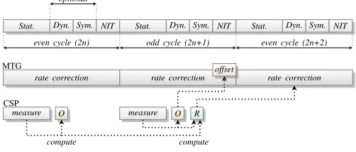
Fig. 7: Rate and offset computation by MTG and CSP.
−7
31 44
50 26 −14
−49
−49 −14 −7
26 31
44
50
(−14 + 44)/2
= 15 Deviation
Values
[image:7.612.339.556.193.277.2]sort
Fig. 8: Fault tolerant midpoint illustration for seven deviation values.
wherepMacroInitialOffset,gMacroPerCycle, andgdStaticSlot are FlexRay parameters. The computation is implemented using cascaded DSP48A1 slices, whose inputs are multiplexed between channels A and B to handle startup requests from either channel. If a subsequent odd frame arrives within the predefined window, the integration attempt is flagged as successful by the CSS module and the CSP commands the MTG state machine to start the Macrotick clock (MTClk) using the computed Macrotick value for this channel. The MTG then generates the Macrotick clock from the Microtick clock (uTClk) using the configured parameter values.
Fig. 7 shows the clock deviation computation for each cycle, once the CC successfully integrates onto the network. The measuring cycle refers to the duration of the static segment, where sync-nodes transmit synchronisation frames which are used to compute rate and offset corrections. During each measurement cycle, the node measures the deviation of time of arrival registered at the node from the calculated time of arrival of the synchronisation frame, which is stored in memory. At the end of measurement phase, the node computes the offset and rate correction factors from the stored values using a fault-tolerant midpoint algorithm. The operation is depicted in Fig. 8, for a cycle that recorded seven deviation values. The real challenge here is that a network may be configured without dynamic and symbol window segments. Hence the offset and rate computations have to be completed consuming a minimum number of cycles to ensure that correction values are available to be applied at the network interval time segment.
ID RAM
A(B) ID
Channel A Dev. Store
Channel B Dev. Store write if found→ID location:
else→new location
Min. deviation for each ID
Upper pipe
Lower pipe
valid count +
midpoint deviation
[image:8.612.335.540.54.222.2]content addressable memory structure
Fig. 9: CAM organisation and fault tolerant mid-point computation for offset correction.
deviation values and the computation of mid-point correction values. As a frame is received, its ID is used to address the slotID RAM, the output of which is used as the address for the deviation store, mimicking a content-addressable memory. The deviation from the expected arrival time of sync frames to their actual arrival time is stored in the deviation store. The upper and lower pipes perform dynamic sorting (descending and ascending) as and when the deviation values are replayed from the store, at the end of the cycle. Dynamic sorting is implemented using a FIFO structure and multiple comparators. Hierarchical comparison is performed from top to bottom (bottom to top) in the upper (lower) pipe. At any level, if the input value is greater (less) than the existing values at that level, the input value is pushed into the FIFO at that level.
For each ID, the multiplexer chooses the minimum deviation among the two channels, in the case of offset computation, and the difference between the corresponding channels in a pair of cycles, in the case of rate computation. The mid-point deviation is the average deviation over the corresponding stages in upper and lower pipe, the stage chosen depending on the number of valid deviation values stored. The MacroTick Generation module uses the computed mid-point deviation values to make corrections to the node’s view of time. Utilising the tagging established by the content-addressable memory and the pipelined architecture, the mid-point computation can be efficiently implemented at system clock rate to meet pro-tocol requirements. A more conventional architecture would require a higher clock rate for this computation. Architectural optimisation also enables us to utilise fewer resources while maximizing performance.
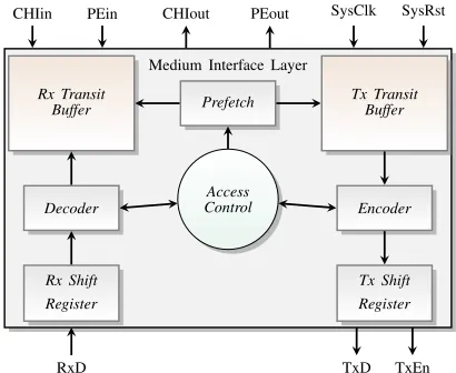
The MIL instantiates independent transmit and receive tran-sit buffers to manage temporary storage of a frame, as shown in Fig. 10. The MIL ensures that medium-access occurs only at slots assigned to the node. The access control state machine handles the bus access, depending on the current slot counter value and slot segment. The access control logic generates and maintains the slot counter and the slot segment, which are used by other modules in the CC. Within each slot, the logic generates control signals called action points, which mark points at which transmission can start (in static and dynamic slots) or end (in dynamic slots).
The signals trigger the encoding logic to start transmission of frame in the transmit buffer, provided the current slot is
Medium Interface Layer
Access Control
Prefetch Tx TransitBuffer Rx Transit
Buffer
Encoder
Tx Shift Register Decoder
Rx Shift Register
TxD TxEn RxD
[image:8.612.53.296.56.176.2]CHIin PEin CHIout PEout SysClk SysRst
Fig. 10: Medium Interface Layer architecture.
allocated to this node. The data to be transmitted is moved to the transmit buffer over a 32 bit data bus. If no data is available for transmission, the node transmits a null frame. The module also handles encoding and serial transmission of data (at the oversampled rate) to be transmitted in the current slot. Decoder functionality is also integrated into this module, which performs bit-strobing, majority-voting, byte-packing and validation of received data at the end of the slot. The transmit interface is implemented using shift registers with gated clocks. This allows us to provide multiple functions with the same set of registers: encode and transmit data bytes, control signals, and symbols. The shift register reads each byte from the transmit buffer, encodes it within the shift register and pushes it to the transmit line at the transmit clock, along with the transmit control signals. At the receiving interface, sampling, bit-strobing and edge synchronisation are implemented using a sequence of shift-register modules: one set samples the data and produces a majority voted bit every cycle, and the second set performs byte-packing of the data. This system offers the advantage of simpler control and higher throughput. The byte-packed data is written into the receive transit buffers. As and when protocol errors or violations are detected (like reception crossing boundary points), appropriate flags are set locally, which are used to validate the data at the slot boundary. At the end of the current slot, the flags are checked to signal valid data, which can then be written into the receive data memory in the host-interface.
enable prefetching and addressing using the slot-cycle-channel complex, as required by the protocol.
Two such MILs are instantiated within the controller to support independent dual channel operation. These modules may transmit and receive data in the same slots, as configured by the host. To facilitate this, we have implemented a config-urable scheduler, which can be configured for priority access (Channel A over B or vice versa) or first-come, first-served mode. High word-length interconnects are used between the data store in host interface and transit buffers within the MIL module to ensure low-latency prefetch and write-back for both channels. Using such an architecture, the prefetching can be handled at system clock rates, without high latency. The physical layer can be configured to support multiple bit-rates of 2.5 Mbps, 5 Mbps or 10 Mbps. The usage of shift register-based encoder/decoder modules simplifies the logic requirements for handling multiple bit-rates.
The interface to the host processor is designed to be compatible with the Processor Local Bus (PLB) interface and AMBA Advanced eXtensible Interface 4 (AMBA AXI4) stan-dards, two of the widely used high-performance low-latency peripheral interconnects for system-on-a-chip (SoC) designs. The host interface supports parameterised widths and a wide range of system and interrupt configurations to provide a rich interface to the host processor (or logic). The control path comprising the command, status and configuration registers are isolated from the datapath and implemented as a register stack. Data corresponding to each cycle, slot, and channel is addressed using an indirect addressing technique. The data pointer is stored at an address determined by the cycle-slot-channel complex. This allows us to use true dual-port Block RAM modules and simpler address generation as opposed to the complex FIFO-based schemes used by existing controllers. Another advantage is that the memory can be configured as a cyclic buffer resulting in an indefinite memory space, as opposed to the limited memory space available in a FIFO-based scheme. The memory space is dynamically allocated at the end of each slot that is configured as a receive slot, only if valid data has been received, thus optimising memory usage. Asynchronous FIFOs are instantiated between the host inter-face and the control/data stores, enabling the host interinter-face to run at a clock speed independent of the PE. Using such a low-level design paradigm, we are able to leverage FPGA resources within the modules of the FlexRay Controller, thereby saving the remaining area for host implementation.
C. Controller Datapath Extensions
Traditional controllers depend on the host processor to read the received data and determine the usefulness of it. The controller issues a data interrupt, to which the processor responds with a status register read followed by a data read request, subsequently receiving the data. These overheads are wasted in the case of frames with irrelevant data (like obsolete or untimely data) or multi-cycle data frames where the processor cannot process the received fragment until more data is available. In the case of critical data frames like error state that require immediate attention, the latency introduced
by the traditional scheme limits the performance of safety-critical systems which rely on host-triggered recovery. With custom extensions, such exceptions can be handled at the controller, which processes the information and informs the host processor (using interrupts). The host retains absolute control, but is not involved in the low-level processing, which is handled instead by the configurable extensions. Fig. 11 describes the functioning of such extensions on the receive-path of our controller.
On the receive path, the extensions can monitor the received data for matching FlexRay message ID, application-based custom headers or timestamp information, contained in the data segment of the FlexRay frame. The FlexRay message ID can be used for application/user defined communication in dynamic segment data frames. An interesting use-case is to embed the error status of the ECU into the message ID, which can trigger a fault-recovery procedure in safety-critical units. Application specific headers may be embedded into the data segment in any frame. Such headers convey information about the data contained in the frame, like sequence number and length, and are particularly useful in the case of large data transfers which are accomplished as multi-cycle transactions on the FlexRay bus. Information in the headers can be used by the controller to re-pack the multi-cycle data. The header processing extensions on the receive path can look for such information and re-organise the segmented data and present it as a single transaction to the host.
Similarly, the timestamp validation extension can be config-ured to reject frames which are obsolete or untimely. On the transmit path, these extensions can insert relevant headers and timestamp information, as configured. Timestamp resolution is configurable, with a finest resolution of one macrotick and maximum length of four bytes. The header is entirely user configurable, and can be matched at the receiver by programming the corresponding registers.
Such extensions on the controller can help extend the functionality and overcome the inherent limitations of the FlexRay network, and are impossible to achieve on discrete controllers. Our pipelined architecture in the transmit and receive paths allows us to add this functionality with no additional latency. Standardising such extensions, automotive networks like FlexRay can be enhanced to implement a data-layer segment that provides security against replay attacks (us-ing timestamps) and a standard methodology to communicate the health state of ECUs (using headers) [26]. Though such enhancements can be handled by the application in software, this would incur additional processing latency and unwanted complexity at the software level (like timing synchronisation).
IV. IMPLEMENTATIONRESULTS
Voting Window
Fle
xRay
Bus
Byte Packer
Transit Memory Slot-Cycle
Filter
Traditional Scheme Custom Extensions
Msg ID filter
Appl. header processing (Data Segment)
Timestamp validation
Decision Block
Receive Data Store
Host processor
Process Data Assigned
Slot-Cycles
Match
Valid Frame
Interrupt
Data read
Critical msg? Multi-cycle msg?
Invalid timestamp? Interrupt (Data/Control) Critical?
Multi-cycle?
[image:10.612.66.553.53.239.2]Stale?
[image:10.612.61.289.289.476.2]Fig. 11: Receive path extensions on custom CC versus traditional schemes.
TABLE II: FlexRay node parameters.
Parameter Value
Number of Cycles 64
Cycle Duration 5 ms
Number of Static Slots 62
Static Slot duration 65 (macroticks) Payload Length (Static) 21 words
Number of Dynamic Slots 10 (max) Symbol Window duration 139 (macroticks)
NIT duration 208 (macroticks)
Sample Clock 12.5 ns
Keyslot ID Assigned Slot 7
Transmission slots Slot 7 in cycles 32 and 62
bus within the FPGA, using captured raw bus transactions from a real FlexRay network (using Bosch E-Ray controllers) communicating using a pre-defined FlexRay schedule; these are stored in on-board memory. The information is replayed to create a cycle accurate replica of transactions on the bus. Our CC is plugged into this FlexRay bus, and configured with the same FlexRay parameters. Table II shows a specific set of parameters which was used for our experiments.
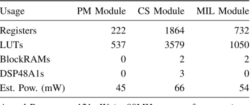
Table III details the resource utilisation of the individual modules of the controller and the power estimates generated by the Xilinx XPower Analyser tool, using activity information from simulation. We have configured the core to support all extensions on the transmit and receive path; a two-byte data header and a four-byte timestamp. The maximum achievable frequency for this configuration was 88 MHz. The core is initialised with parameters using a logic-based host-model over a PLB/AXI interface. The actual power measured using a power supply probe during operation in hardware is also shown.
Table IV compares the resource utilisation of our imple-mentation against the platform agnostic E-Ray IP core on the
TABLE III: CC Implementation on hardware.
Usage PM Module CS Module MIL Module
Registers 222 1864 732
LUTs 537 3579 1050
BlockRAMs 0 2 2
DSP48A1s 0 3 0
Est. Pow. (mW) 45 66 54
Actual Power 121mW (at 80MHz system frequency)
same Altera Stratix-II device. For the purpose of comparison, the consolidated utilisation on a Xilinx Spartan 6 is also shown in the same table. It can be observed that the hardware centric approach results in much better utilisation of the het-erogeneous resources, leading to a compact implementation. The design can also be easily ported to other Xilinx and Altera devices, and to other platforms with a little more effort. The resource utilisation and optimisations that we have achieved in comparison with the platform agnostic E-Ray core is significant enough to justify the somewhat reduced portability. With DSP inference disabled, our implementation consumed 8282 LUTs and 5248 Registers (on the Stratix-II), which is still less than the E-Ray core. Another advantage is that the power consumption at full operation on a Spartan 6 device is below the power consumed by typical stand-alone controller chips like the Infineon CIC-310, which uses the E-Ray IP module [27] and consumes about 150 mW in normal operating mode.
[image:10.612.313.563.292.397.2]TABLE IV: Comparison of implementations.
Utilisation
E-Ray[24] Proposed Implementation
Extentions Disabled Enabled
Altera Stratix II Xilinx Spartan 6
Registers 7754 4966 4910 5612
LUTs 12780 7856 7978 8767
BRAMs 23×M4K 33×M4K 5×9k + 12×18k
5×9k + 13×18k
DSPs — 12×9-bit 3×DSP48A1
Microblaze Interrupt
Controller Radix-2
FFT
CFAR
DPR
System Interfaces
FlexRay Interface
System Memory
Traffic Generator
BUS A
JTAG RS232 Sensor
[image:11.612.55.296.71.365.2]Data
Fig. 12: Integrated ECU function on Spartan-6 FPGA.
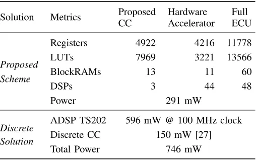
and is built using Xilinx FFT IP cores and pipelined logic which performs target detection using a constant false alarm rate (CFAR) scheme [28]. The test data generates 1024 data points every 30 ms, which are transformed to the frequency domain by the FFT module. The CFAR module performs detection on the frequency domain data using multi-stage pipelined logic and writes results into the dual-port RAM. The processor is then interrupted, and it consolidates the data over a configurable number of cycles. The controller is configured with parameters defined in Table II. Thus at cycles 32 and 62, consolidated results are sent on the FlexRay bus. Table V details the resource utilisation and power consumption measured during operation in hardware. Such an application would otherwise require specialised DSP processors, since the latency cannot be met by software implementation on a general purpose processor [28]. Similar performance can be obtained by interfacing high performance DSP devices like the Analog Devices ADSP-TS202S [29] with a standalone FlexRay controller like the Infineon CIC-310 or Freescale S12XF [30], but the node would consume much higher power overall than the integrated FPGA implementation. The key advantage here is that integrating ECU functionality and the network interface on the same device only increases power usage marginally, and this interface can be shared between multiple functions on the same FPGA.
[image:11.612.53.298.75.362.2]MicroBlaze offers a low power, low throughput processing option for sensor applications. Alternatively, hybrid platforms like the Xilinx Zynq can be used for more compute intensive and real-time applications since they offer a more powerful
TABLE V: Spartan-6 implementation of ECU on Chip.
Solution Metrics Proposed
CC
Hardware Accelerator
Full ECU
Proposed Scheme
Registers 4922 4216 11778
LUTs 7969 3221 13566
BlockRAMs 13 11 60
DSPs 3 44 48
Power 291 mW
Discrete Solution
ADSP TS202 596 mW @ 100 MHz clock
Discrete CC 150 mW [27]
Total Power 746 mW
hard ARM processor. By using AXI-4 for communication between the CC and the host, our design can be used with the ARM in the Zynq (consuming 5612 Registers, 8685 LUTs and 2 DSP48E1s) or with a MicroBlaze soft processor, or a custom hardware ECU.
V. CASESTUDIES
We now present three distinct case studies that showcase the effectiveness of the custom extensions in the context of existing or proposed automotive applications. In each use case, we observe that the application can leverage the intelligence built into the controller, leading to smarter and more efficient systems when compared to standard implementations.
A. Error Detection and Fall-Back for Safety Critical Systems Safety-critical systems employ redundant or fall-back modes, which enable minimum guaranteed functionality, even in the presence of hardware/software faults. One of the critical parameters in such a system is the time taken to switch to fall-back mode once a fault has been identified. For this experiment, we model a brake-by-wire system comprising two MicroBlaze ECUs on the FlexRay network; the brake sensor ECU, which interfaces to the sensor modules, and the actuator ECU, which issues commands to the braking system. Each ECU incorporates fall-back logic which is triggered when a fault-status message is received. These status messages are generated by centralised fault detection logic that monitors bus transactions for unsafe commands/data. The sensors and actuators are modelled using memories: sensor data is gen-erated from a Sensor BRAM, and commands are pushes to the Actuator BRAM. The sensor ECU combines inputs from the different sensor interfaces periodically and passes it over the FlexRay bus to the processing ECU. The processing ECU uses this data to compute commands and issues them to the actuators. Both ECUs run software routines on the popular FreeRTOS platform. A simplified model of the test setup is shown in Fig. 13.
FPGA
ECU1 ECU2
ECU3
Sensor1
Sensor2
Sensor3
Actuator1
Actuator2
FlexRay
t0 t1 t2
t4
t3
msg1
[image:12.612.332.542.52.176.2]msg2
Fig. 13: Test setup for brake-by-wire system.
0 0.2 0.4 0.6 0.8 1 1.2
·104
SA RT Hardw
are
3,540
9,050 180
Processing Time (ns)
Fig. 14: Latency distribution for interrupt-based critical data processing.
be issued to actuator ECU over the FlexRay bus. The fault-detector logic detects the error and transmits the error code in the next slot assigned to it. A normal controller decodes this message, passes it to the MicroBlaze processor, where the data is processed to trigger fall-back mode. The latency from the transmission of the error message to the triggering of fall-back mode is largely determined by the interrupt-based data passing mechanism used in off-the-shelf controllers. Even for an RTOS-based (real time) system, this latency can be significant, and was measured at an average of 9.05ms for our implementation, as illustrated in Fig. 14.
By moving such critical data processing to the controller, it becomes possible to significantly reduce this delay and enhance the determinism of the system. To quantify this, a processing extension that detects packets on a user-configured slot with a user-specified data header is enabled on the CC. On detecting this combination, the controller can either process the remaining data for specific patterns, or trigger an interrupt. In this particular experiment, it is configured to process the critical error flags and the consecutive error numbers to decide whether to trigger fall-back mode. This generates a direct interrupt to the MicroBlaze processor and enables fall-back mode, resulting in a faster and more consistent turnaround time (average 50×faster than RTOS), as shown in Fig. 14.
We have also repeated the experiment using the Xilinx standalone (SA) OS, the lightweight minimalistic OS for MicroBlaze. It can be observed from Fig. 14 that though the simplified standalone OS results in lower average interrupt latencies than the RTOS, it results in a larger spread of latencies.
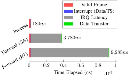
0 0.2 0.4 0.6 0.8 1
·104
Forw ard(R
T) Forw
ard(SA) Process
9,285ns
3,780ns
180ns
Time Elapsed (ns) Valid Frame Interrupt (Data/TS)
IRQ Latency Data Transfer
Fig. 15: Timestamp processing at interface.
B. Time-Awareness for Messages
A major security risk in time-triggered systems like FlexRay is the lack of time-awareness for messages. By monitoring bus transactions, an external agent can easily employ simple replay attacks, flooding the bus with stale data, as described in [31]. The FlexRay protocol leaves this vulnerability to the higher layer applications to manage. In our controller, the transmit path allows messages to be optionally time-stamped to make the message time-aware, at the cost of increased payload size. By inserting the header and timestamp within the data segment of the FlexRay frame, it is transparent to other FlexRay controllers present on the network, ensuring interoperability with off-the-shelf controllers. With timestamps enabled, the receive path can be configured to automatically drop frames which are outside an allowed time window. This creates a basic security layer at each ECU, which can be augmented further by incorporating encryption/decryption logic in the datapath.
An interesting use-case is in high-performance gateways that move data between network clusters. With traditional interfaces, messages arriving from each interface will be for-warded to the switch logic, which decides whether to forward the data to its destination or drop it because it has expired. By building intelligence into the controller, the the validity of data can be determined before it is forwarded to the switching logic. We modify the experimental setup in Section 13 to model a a gateway configured to discard untimely data, either at the processing logic (MicroBlaze), mimicking off-the-shelf interfaces, or at the interface using our enhanced controller extensions. Our tests show that the interface can process the timestamp and discard the message within 180 ns of frame reception. A standard approach consumes a further 3.6 and 9.1us on average, for standalone (SA) and RTOS (RT) respectively, as shown in 15, since the data must be processed by the host.
C. Handling Volume Data at Interfaces
[image:12.612.66.287.56.196.2]0 10 20 30 40 50 60
SAOf f RT Of
f SA On RT On
63.4us
53.8us
27.4us
25.0us
Processor Time Consumed (us) IRQ Latency 64 beat Transfer Subseq. IRQ Lat.
[image:13.612.332.541.53.200.2]Subseq. Burst
Fig. 16: Data re-packing for multi-cycle data transfers.
packing/re-packing to the controller interface, the processing logic can overlap the computation with data reception, en-abling it to run at lower frequencies and hence consume lower power.
To demonstrate this, we use the experimental setup for the radar-based cruise control ECU, described earlier in Sec-tion IV. The data from the radar sensor is received over the FlexRay bus in bursts of 256 bytes, the maximum payload size defined by FlexRay standard. The MicroBlaze processor runs the standalone (SA) OS from Xilinx. In a normal design, the processor is interrupted each time a block of data is received. The processor responds with the first data read request 12ms (worst-case) after receiving the interrupt, with the burst read consuming a further 3.84ms. This is repeated over four cycles to complete the data transfer, cumulatively consuming 63.36ms.
We then test the same application with en extension that allows the controller to intelligently buffer the entire frame in a buffer, only interrupting the processor at the end of the transaction. This enables the processor to issue back-to-back reads from the controller completing the entire data movement in 27.36ms from the reception of the interrupt. To provide a balance between multi-cycle and single-cycle data, the design has been constrained to handle up to four data cycles at full payload size. To support larger data sizes, larger buffer memories must be added to the the controller, resulting in higher device utilisation, however, this may be a tolerable cost for some ECUs, and the CC architecture supports it.
The experiment was also repeated using the FreeRTOS -based (RT) software, which provided better determinism than the standalone OS, resulting in a lower worst-case interrupt latency, as shown in Fig. 16.
VI. DISCUSSION
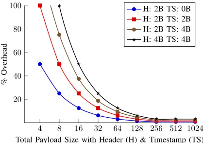
The FlexRay protocol does not define the usage of headers within the data segment, which is entirely dependent upon user implementation. While the usage of headers and time-stamps within data provides the aforementioned advantages, it may result in significant payload overheads for small data sizes, while also limiting the payload capability of a FlexRay frame. Fig. 17 compares the overheads associated with different configurable values for the application header and timestamp, as a function of the payload size. As can be observed, at lower payload sizes, the inclusion of a timestamp and application
4 8 16 32 64 128 256 512 1024 20
40 60 80 100
Total Payload Size with Header (H) & Timestamp (TS)
%
Ov
erhead
[image:13.612.71.284.53.177.2]H: 2B TS: 0B H: 2B TS: 2B H: 2B TS: 4B H: 4B TS: 4B
Fig. 17: Overheads for including headers and timestamps.
header results in large overheads, but for large payload sizes, the penalty paid is very small. Beyond the maximum payload size of256bytes, additional data has to be handled as multi-cycle transactions, causing the curve to flatten out for higher payload sizes. Since the application header and timestamp data is inserted within the data segment of the FlexRay frame, it is transparent to other FlexRay controllers on the network, ensuring interoperability with standard controllers.
We have purposefully designed the controller’s architecture to coexist with ECU functions on the same FPGA. Doing so allows us to leverage the computational capabilities of FPGAs for implementing ECU functions, while no longer requiring a discrete network controller. We can also incorporate partial reconfiguration to allow multiple applications to interface with the bus through a single controller and to define fault-tolerant ECUs for safety-critical functions [32].
Furthermore, timestamps and data processing capabilities within the controller can also be used extensively for func-tional validation of novel applications, architectures and net-work features. On a large enough FPGA like the Virtex-7, we can integrate up to 10 ECUs, network controllers, and the actual network to create a validation platform (replicating an actual car network) for functional verification [33].
VII. CONCLUSION
We aim to investigate extending this controller for use with partial reconfiguration to provide flexible use of the FPGA fabric, enabling further sharing of communication resources between ECUs. We intend to develop intelligent FlexRay nodes and switches on reconfigurable hardware that are energy efficient and allow us to explore more advanced network setups. Finally, the principles demonstrated in this paper are also applicable to other time-triggered interfaces, and we hope to explore this for time-triggered Ethernet.
REFERENCES
[1] S. Chakraborty, M. Lukasiewycz, C. Buckl, S. Fahmy, N. Chang, S. Park, Y.Kim, P. Leteinturier, and H. Adlkofer, “Embedded Systems and Software Challenges in Electric Vehicles,” inProc. Design, Automation and Test in Europe (DATE) Conference, 2012.
[2] S. Shreejith, S. A. Fahmy, and M. Lukasiewycz, “Reconfigurable Computing in Next-Generation Automotive Networks,”IEEE Embedded Systems Letters, vol. 5, No. 1, pp. 12–15, 2013.
[3] I. Sheikh, M. Hanif, and M. Short, “Improving information throughput and transmission predictability in Controller Area Networks,” inProc. International Symposium on Industrial Electronics (ISIE). IEEE, 2010, pp. 1736–1741.
[4] J. K¨otz and S. Poledna., “Making FlexRay a Reality in a Premium Car,” inProc. of the SAE International, 2008.
[5] Specification of FlexRay Interface Version 3.2.0, AUTOSAR Std. [Online]. Available: http://www.autosar.org
[6] FlexRay Communications System, Protocol Specification Version 2.1 Revision A, FlexRay Consortium Std., December 2005. [Online]. Available: http://www.flexray.com
[7] P. Milbredt, B. Vermeulen, G. Tabanoglu, and M. Lukasiewycz, “Switched FlexRay: Increasing the Effective Bandwidth and Safety of FlexRay Networks,” inProc. Conference on Emerging Technologies and Factory Automation (ETFA), 2010.
[8] T. Schenkelaars, B. Vermeulen, and K. Goossens, “Optimal Scheduling of Switched FlexRay Networks,” inProc. Design, Automation and Test in Europe (DATE) Conference, 2011.
[9] M. Lukasiewycz, S. Chakraborty, and P. Milbredt, “FlexRay Switch Scheduling - A Networking Concept for Electric Vehicles,” inProc. Design, Automation and Test in Europe (DATE) Conference, 2011. [10] T. Forest, A. Ferrari, G. Audisio, M. Sabatini, A.
Sangiovanni-Vincentelli, and M. Di Natale, “Physical Architectures of Automotive Systems,” in Proc. Design, Automation and Test in Europe (DATE) Conference, 2008.
[11] M. Lukasiewycz, M. Glaß, J. Teich, and P. Milbredt, “FlexRay Schedule Optimization of the Static Segment,” inProc. International Conference on Hardware/Software Codesign and System Synthesis (CODES+ISSS), 2009.
[12] K. Schmidt and E. G. Schmidt, “Message Scheduling for the FlexRay Protocol: The Static Segment,”IEEE Transactions on Vehicular Tech-nology, vol. 58, No. 5, pp. 2170–2179, 2009.
[13] E. G. Schmidt and K. Schmidt, “Message Scheduling for the FlexRay Protocol: The Dynamic Segment,” IEEE Transactions on Vehicular Technology, vol. 58, No. 5, pp. 2160–2169, 2009.
[14] J. J. Nielsen and H. P. Schwefel, “Markov Chain-based Performance Evaluation of FlexRay Dynamic Segment,” inProc. International Work-shop on Real Time Networks, 2007.
[15] B. Kim and K. Park, “Probabilistic Delay Model of Dynamic Message Frame in FlexRay Protocol,”IEEE Transaction on Consumer Electron-ics, vol. 55, Issue 1, pp. 77–82, 2009.
[16] X. HeI, Q. Wang, and Z. Zhang, “A Survey of Study of FlexRay Systems for Automotive Net,” inProc. International Conference on Electronic and Mechanical Engineering and Information Technology, 2011. [17] C. Schmutzler, A. Lakhtel, M. Simons, and J. Becker, “Increasing energy
efficiency of automotive E/E-architectures with Intelligent Communi-cation Controllers for FlexRay,” inProc. International Symposium on System on Chip (SoC), 2011.
[18] J. Sobotka and J. Novak, “FlexRay controller with special testing capabilities,” inProc. International Conference on Applied Electronics (AE), 2012, pp. 269–272.
[19] J. Y. Hande, M. Khanapurkar, and P. Bajaj, “Approach for VHDL and FPGA Implementation of Communication Controller of FlexRay Controller,” inProc. International Conference on Emerging Trends in Engineering and Technology, ICETET, 2009.
[20] Y.-N. Xu, Y. E. Kim, K. J. Cho, J. G. Chung, and M. S. Lim, “Implementation of FlexRay Communication Controller Protocol with Application to a Robot System,” inProc. IEEE International Conference on Electronics, Circuits and Systems (ICECS), 2008.
[21] Y.-N. Xu, I. Jang, Y. Kim, J. Chung, and S.-C. Lee, “Implementation of FlexRay Protocol with an Automotive Application,” inProc. Inter-national SoC Design Conference (ISOCC), 2008.
[22] P. Szecowka and M. Swiderski, “On Hardware Implementation of FlexRay Bus Guardian Module,” inProc. International Conference on Mixed Design of Integrated Circuits and Systems (MIXDES), 2007. [23] G. N. Sung, C. Y. Juan, and C. C. Wang, “Bus Guardian Design for
Au-tomobile Networking ECU Nodes Compliant with FlexRay Standards,” inProc. International Symposium on Consumer Electronics, 2008. [24] Product Information : E-Ray IP Module, Robert Bosch GmbH, July
2009.
[25] FRCC2100 : Product Brochure, Freescale FlexRay Communications Controller Core, IPextreme, Inc.
[26] S. Shreejith and S. A. Fahmy, “Enhancing Communication On Auto-motive Networks Using Data Layer Extensions,” inProc. International Conference on Field Programmable Technology (FPT), 2013, pp. 470– 473.
[27] SAK-CIC310-OSMX2HT, FlexRay Communication Controller Data Sheet, Infineon Technologies AG, June 2007.
[28] J. Saad, A. Baghdadi, and F. Bodereau, “FPGA-based Radar Signal Processing for Automotive Driver Assistance System,” inProc. Interna-tional Symposium on Rapid System Prototyping, 2009.
[29] F. Greg, “EE170 : Estimating Power for the ADSP-TS202S Tiger-SHARC Processors,” Analog Devices, Tech. Rep., 2006.
[30] MC9S12XF512 Reference Manual, Rev.1.20 ed., Freescale Semiconduc-tors, Nov 2010.
[31] I. Rouf, R. Miller, H. Mustafa, T. Taylor, S. Oh, W. Xu, M. Gruteser, W. Trappe, and I. Seskar, “Security and privacy vulnerabilities of in-car wireless networks: a tire pressure monitoring system case study,” in
Proc. USENIX Conference on Security, 2010.
[32] S. Shreejith, K. Vipin, S. A. Fahmy, and M. Lukasiewycz, “An Approach for Redundancy in FlexRay Networks Using FPGA Partial Recon-figuration,” in Proc. Design, Automation and Test in Europe (DATE) Conference, 2013, pp. 721–724.
[33] S. Shreejith, S. A. Fahmy, and M. Lukasiewycz, “Accelerating Validation of Time-Triggered Automotive Systems on FPGAs,” inProc. Interna-tional Conference on Field Programmable Technology (FPT), 2013, pp. 4–11.
Shanker Shreejith(S’13) received the B.Tech
de-gree in electronics and communication engineering from University of Kerala, India, in 2006.
From 2006 to 2008, he was an FPGA design and development engineer. From 2008 to 2011, he was a scientist at the Vikram Sarbhai Space Centre, Trivan-drum, under the Indian Space Research Organisation (ISRO). Since 2011, he has been a Ph.D. candidate at the School of Computer Engineering, Nanyang Technological University, Singapore, working on reconfigurable computing in automotive systems.
Suhaib A. Fahmy (M’01, SM’13) received the
M.Eng. degree in information systems engineering and the Ph.D. degree in electrical and electronic engineering from Imperial College London, UK, in 2003 and 2007, respectively.
From 2007 to 2009, he was a Research Fellow at Trinity College Dublin, and a Visiting Research Engineer with Xilinx Research Labs, Dublin. Since 2009, he has been an Assistant Professor with the School of Computer Engineering at Nanyang Technological University, Singapore. His research interests include reconfigurable computing, high-level system design, and computational acceleration of complex algorithms.