Effect of Microstructural Refinement on Ductility Deterioration
of High Silicon Ferritic Spheroidal Graphite Cast Iron Caused by Cyclic Heating
Hung-Mao Lin
*1, Truan-Sheng Lui
*2and Li-Hui Chen
Department of Materials Science and Engineering, National Cheng Kung University, Tainan 701, Taiwan, R.O. China
This investigation applies cyclic heating and cooling to elucidate the effect of microstructural refinement on the tensile elongation deterioration of ferritic spheroidal graphite cast iron. In order to eliminate the oxidation factor, the cyclic heating/cooling test was performed in a
1:330:133Pa ambient vacuum atmosphere with cyclic heating at a maximum temperature of 1023 K. Severe embrittlement accompanied by intergranular fracture occurred after the ferritic spheroidal graphite cast iron was subjected to a certain number of heating and cooling cycles. A fair amount of inevitable inclusion particles were found to agglomerate in the eutectic cell boundary region, and so the cyclic heating induced embrittlement can be recognized to be strongly dependent on the solidification cooling rate of the materials. Based on experimental evidence, the cracking evolution can be divided into three steps: (1) crack initiation from the vicinity of the eutectic cell boundary at the surface, (2) crack linking and major crack formation, and (3) major crack inward extension. Cyclic heating cracks are mainly initiated at the eutectic cell boundary where a fair amount of MgO inclusions dispersed, and consequently propagated along the annealed eutectic cell boundary. While investigating the plastic deformation behaviors around the above mentioned MgO inclusions pertaining to the crack initiation and crack propagation, typical etch pit evidence was observed in the vicinity of the cell boundary area.
(Received March 4, 2003; Accepted May 8, 2003)
Keywords: cyclic heating, solidification cooling rate, ferritic spheroidal graphite cast iron, etch pit, tensile elongation deterioration
1. Introduction
Spheroidal graphite (SG) cast iron has been applied as a heat resistant components, such as guide plates for hot rolling equipment, aluminum casting related ingot molds or exhaust manifolds etc.1–3) In these cases, SG cast iron components periodically operate at an elevated temperatures of up to 1173 K and, in particular, are subjected to cyclic thermal shocks from heating/cooling.4) High silicon spheroidal graphite cast iron was often used as one of the most promising candidate alloys for these components due to its castability, low oxidation and wear resistance.5,6)Based on our earlier investigations, a steeper temperature gradient will induce severe thermal stress on such a component and cracks will appear within very short heating cycles even without any external load. However, a repetitive thermal cycle will cause deterioration in the mechanical properties of cast iron. This has been confirmed as a common phenomenon that has been described as the thermal fatigue fracture problem for many alloys.7)Various fracture behaviors have been clarified that are strongly dependent on the microstructural features of each sample, and some common factors include thermal conductivity, thermal-expansion coefficient, Young’s mod-ulus and structural stability.1–7)
For ferritic SG cast iron in our previous studies, MgO inclusions generally tended to cluster in the eutectic cell-wall region. This was the dominant factor causing a deterioration in tensile properties after the specimen suffered a cyclic heating process.8–14)In this case, in spite of the tensile tested be performed at room temperature, ductility deterioration caused by intergranular fracture was identified. This raises the questions of how the dispersed MgO inclusions affect the intergranular fracture behavior, and the effect of the eutectic cell wall morphology during these severe cyclic heating/
cooling processes on reliability. Consequently, the tensile ductility deterioration of a high silicon spheroidal graphite cast irons after being subjected to cyclic heating was investigated, with special emphasis on the refining effect of the morphology related to the dispersion of MgO inclusions that inevitably distributed at the solidificational boundary of eutectic cells.
2. Experimental Procedure
The chemical compositions of the high silicon ferritic SG cast irons used in this study are listed in Table 1. Samples were prepared by melting high-purity pig iron, ferro-silicon, and low-carbon silicon steel in a high frequency induction furnace. After using Fe–45 mass% Si–8 mass% Mg– 2.5 mass% RE ferro-silicon alloy as spheroidizer and Fe– 75 mass% Si alloy for inoculation, then the melt was cast into Y-shaped iron mold and sand molds respectively (Fig. 1) to vary the solidification rate. The ferritization procedure followed a typical two-stage isothermal treatment, in which all specimens were maintained at 1203 K for 3 hours, then furnace cooled to 1093 K for a second isothermal holding of 5 hours and finally furnace cooled to room temperature. The image analyzer (Inspectron software) gathered quantitative analysis data, as shown in Table 2, and the optical micro-structure of each specimen, as shown in Fig. 2. To reveal the morphology of eutectic cell walls, specimens were electro-chemically etched in Morries solution (25 g CrO3: 133 cm3
glacial acetic acid: 7 cm3 H
2O) with a constant applied
[image:1.595.303.550.755.783.2]voltage of 5 volts. The electro-chemically etched micro-structure of each specimen is shown in Fig. 3.
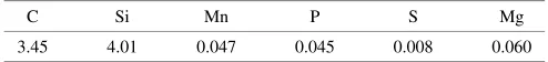
Table 1 Chemical composition of the SG cast irons used in this study.
C Si Mn P S Mg
3.45 4.01 0.047 0.045 0.008 0.060
*1Graduate Student, National Cheng Kung University.
*2Corresponding author: E-mail: [email protected] 2003 The Japan Institute of Metals
To investigate the deterioration rate of tensile properties after the material suffered a certain numbers of heating cycles, the specimens were alternately heated in a vacuum furnace (pressure1:330:133Pa) for 8 minutes to prevent oxidation. However, all specimens were then rapidly cooled in water (2985K). After a certain number of thermal
cycles, tensile testing was performed at room temperature with an initial strain rate of 3:3103s1. In addition,
10 mm15 mm50 mmsquare shape specimens were also used to examine the crack initiation site and the propagation path. For the purpose of identifying the microstructural evolution in the vicinity of thermal cracks, electrochemical etching with Morris solution,15–20) was applied to acquire etching pits in the specific locations.
Tensile fracture surfaces were examined with a Scanning Electron Microscope (SEM), Energy Dispersive Spectro-scopy (EDS), and a Scanning Auger Microprobe (SAM) to detect the fracture morphology. Furthermore, in order to verify the degree of segregation on the intergranular fracture
[image:2.595.46.292.63.243.2]Fig. 1 The dimension of Y-shaped sand mold and permanent mold.
Table 2 Quantitative data of area fraction of nodule graphite (Ag), average
inter-spacing (Sg), graphite nodule size (Dg), average grain size of ferrite
matrix (Df) and mean size of cell wall region (De).
Specimens Ag(%) Sg(mm) Dg(mm) Df(mm) De(mm2)
S-L 14.5 75.3 46 43 9500 S-M 14.3 68.5 38 38 8200 S-S 13.9 40.5 25 34 2560
M 13.2 28.6 18 31 670
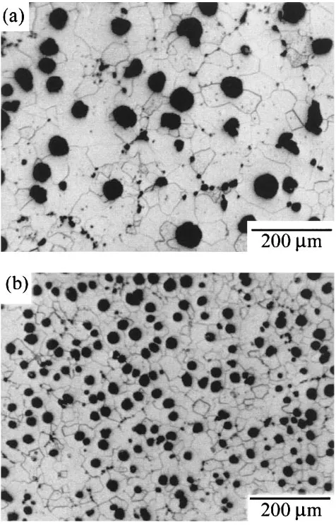
Fig. 2 Optical micrographs of the test specimens after ferritization: (a) S-L and (b) M.
[image:2.595.306.550.105.169.2] [image:2.595.311.543.201.584.2] [image:2.595.50.288.296.668.2]surface, a group of pre-notched specimens were also cyclically heated to the identical cycle number for subsequent
in-situfracture testing in the SAM chamber at 223 K prior to SAM analysis.
3. Results
3.1 Effect of solidification cooling rate on the variation of eutectic cell morphologies
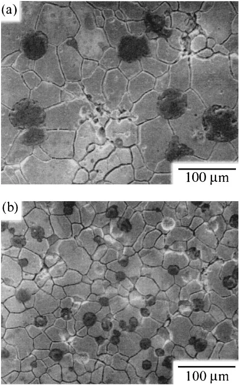
From previous investigations,8–10)it is clear that the tensile properties of SG cast iron at elevated temperatures are strongly dependent on the feature of the eutectic cell morphology. Figure 3 shows the electrochemically-etched ferritic SG cast iron, the morphology of the eutectic cell wall is marked by arrows. According to observations of the microstructure using scanning electron microscopy (SEM), as depicted in Fig. 4, many etched pits and inclusions can be found in a narrow zone of eutectic cell wall. It should be noted that the width of this cell wall zone is reduced significantly as the solidification rate increases, and a distinct change on the number of inclusion particles can be detected. As we see in Fig. 4, a slower solidification cooling rate led to a coarser eutectic cell size resulting in a thicker eutectic cell wall. Furthermore, the MgO inclusions are likely to cluster or
disperse in the cell wall region, increasing the possibility of intergranular cracks appearing in the earlier stage of heating cycles. This will be discussed later. For quantitative comparison, Fig. 5 shows the relationship between nodule size and mean size of cell wall region. The mean size of the cell wall region could be significantly refined by increasing solidification cooling rate.
3.2 Effect of microstructural refinement on tensile ductility deterioration after cyclic heating
The tensile elongation data before cyclic heating testing are shown in Fig. 5. Worthy of notice is the specimen tensile tested at 673 K.9,13,14)For these specimens, the intergranular fracture surface varied according to the eutectic cell wall
Fig. 4 SEM images of the electrochemically etched specimens: (a) S-L and (b) M.
20
25
30
35
40
45
50
15
Nodule Size,
D
g/
µ
m
0
4
8
12
16
20
Elongation (%)
Room Temperature
673K
R.T
673K
C+IG C+IG
D+IG
IG
(a)
0
2000 4000 6000 8000 10000
Mean Size of Cell Wall,
De
/
µ
m
20
4
8
12
16
20
Elongation (%)
Room Temperature
673K
R.T
673K
C+IGC+IG
D+IG IG
(b)
Fig. 5 (a) the graphite nodule size (Dg) of the specimen vs. tensile
elongation of the specimens has tested at room temperature (R.T) and at 673 K; (b) the tensile elongation of the specimens has tested at room temperature (R.T) and at 673 K as a function of mean size of cell wall region (De). (D: dimple fracture, C: cleavage fracture and IG: intergranular
[image:3.595.323.528.76.534.2] [image:3.595.51.287.380.761.2]region size. On the other hand, only cleavage and dimple fracture pattern could be observed when the specimen was tensile tested at room temperature.
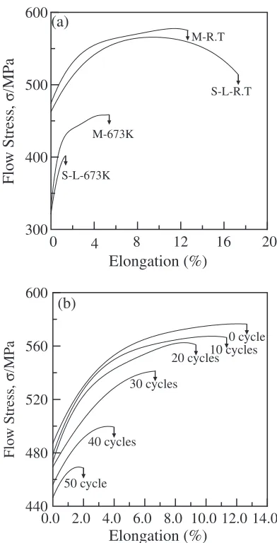
The effect of microstructural refinement on the tensile properties of ferritic SG cast iron at room temperature after the material suffered a certain number of heating cycles can be seen in Fig. 6, which shows a typical example of M specimen. It is clear that the deterioration in tensile properties can be induced with increased heating cycles. Figure 7 depicts the relationship between tensile data and the number of thermal cycles, In particular, the specimens with coarser eutectic cell wall region size show a remarkable intergranular fracture surface, even the specimen tensile tested at room temperature (Fig. 8). Tensile elongation data significantly decreases as the number of heating cycles is increased.
According to definition, the deterioration rate of tensile elongation after cyclic heating is given as deterioration rate =
1 ðMcycles=M0Þ, where M0 is the tensile elongation before
cyclic heating;Mcyclesis the tensile elongation after a certain
number of thermal cycles. As can be seen from Fig. 9, the deterioration rate can be improved by microstructural refinement resulting from increasing the solidification cool-ing rate. Based on the tensile data, as shown in Figs. 7 and 9,
however, the deterioration rate can be easily evaluated through a tensile test before or after the specimens suffered from a certain number of heating cycles. Thermal fatigue life could be predicted, if the tensile elongation data and its relationship with heating cycles could be understood quanti-tatively.
The deterioration in elongation after cyclic heating testing can be correlated with the change in microstructural feature caused by a slower solidification cooling rate. EDS spectra data obtained from the vicinity of the eutectic cell boundary region where marked inclusion particles are present, as indicated in Fig. 10(a), have confirmed these inclusion particles on the eutectic cell wall (region A) are mainly composed of magnesium, phosphorus, oxygen and cerium, as shown in Fig. 10(b). Moreover, Fig. 10(c) can clarify the secondary dimple void on the intergranular fracture facets (region B). These voids consist simply of magnesium and oxygen peaks. The location of those voids is comparatively far from the central region of the eutectic cell boundary. However the secondary dimple voids on the facets tend to disappear in the intergranular facet (region C), though distinct magnesium and oxygen peaks can still be detected (as shown in Fig. 10(d)).
From the features mentioned above, it is reasonable to suggest that the microstructural evolution of heat resistant SG cast iron is closely related to the solidification cooling rate and subsequent variations of MgO inclusion, as well as the magnesium segregation in the annealing grain boundaries.
3.3 Crack initiation and propagation after cyclic heat-ing
As can be seen in Fig. 11, cracks initiated in the central region among nodular graphite after the specimens suffered a certain numbers of heating cycles. The effects of micro-structural refinement on the crack initiation feature of ferritic spheroidal graphite cast iron under above mentioned cyclic heating test were examined. Though most of the cracks initiated from MgO inclusion particles, the average size of an initial crack reduced as the solidification cooling rate of the samples increased, as shown in Figs. 11(a) and (b). As the number of heating cycles increased, individual cracks tended to link up with each other for further propagation (Fig. 11(c)). However, the development of major cracks during tensile deformation was strongly dependent on the solidificational microstructure.
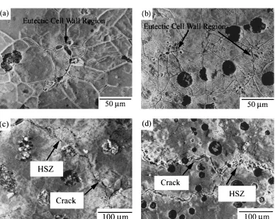
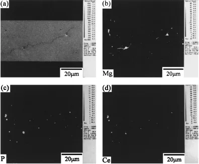
Figure 12 shows a cyclic heating induced crack. Figs. 12(c) and (d) show the locus of the cracking. The composition locus of cell boundaries can be correlated with the data, as seen in Fig. 13(a). Electron probe micro-analyser analysis (EPMA) implies the path of an inclusion-induced crack should be correlated to the presence of magnesium, oxygen and phosphorus containing inclusions. Also, the locus of an intergranular crack as shown in Figs. 13(b)–(d), is a consequence of atomic magnesium segregation and magne-sium oxides in both the annealed ferritic grain boundaries and solidification grain boundaries. From Fig. 5, it is clearly seen that the solidification cooling rate will affect the micro-structure of eutectic cell boundaries. The electrochemically etched feature can be easily identified by comparing the results of Fig. 3. This comparison also implies that
micro-0 4 8 12 16
Elongation (%)
20 300 400 500 600Flo
w Stress,
σ/
MP
a
(a)
M-R.T S-L-R.T M-673K S-L-673K0.0 2.0 4.0 6.0 8.0 10.0 12.0 14.0
Elongation (%)
440 480 520 560 600 Flo w Stress, σ / MP a(b)
50 cycle 40 cycles 30 cycles20 cycles10 cycles 0 cycle
[image:4.595.71.267.71.455.2]Fig. 8 The morphology of the S-M specimen fractured surface tensile tested before cyclic heating at (a) room temperature; (b) 673 K; after (c) 10 cycles and (d) 20 cycles.
0 10 20 30 40 50 Number of Cycles
60 350
400 450 500 550 600
UTS,
σ
/
MP
a
S-L S-M S-S M
(a)
0 10 20 30 40 50 Number of Cycles
60 320
360 400 440 480 520
Y
ield Stress,
σ
/
MP
a
S-L S-M S-S M
(b)
0 10 20 30 40 50 Number of Cycles
60 0
4 8 12 16 20
Elongation (%)
S-L S-M S-S M (c)
[image:5.595.115.485.80.764.2] [image:5.595.104.496.416.733.2]structural refinement is an important factor in improving tensile properties that results from suppressing intergranular fractures.
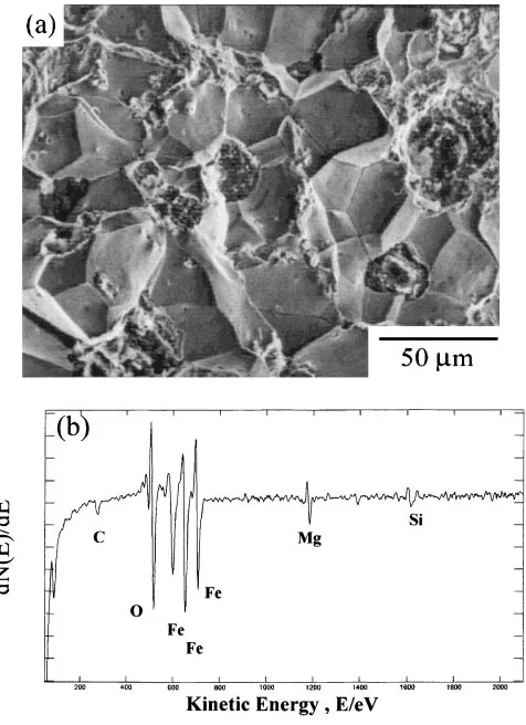
Furthermore, an S-L sample with coarse microstructure which suffered an identical number of heating cycles was used anin-situfracture test at 223 K. Figure 14(a) reveals a similar intergranular fracture pattern to that shown in Fig. 10 accompanied by a fair amount of inclusion particles. The
fractography feature corresponds to the inclusion particles (region A), the secondary dimple voids (region B) and the smooth intergranular facets (region C). From the SAM spectra of the flat-grain facet shown in Fig. 14(b), evidently, a certain amount of oxygen, silicon and magnesium containing segregation can be detected at the smooth grain boundaries. From Fig. 15(a), owing to the Auger peaks of magnesium detected on the inclusion particles, which are actually the sites of oxidation state of magnesium, it is reasonable to suggest that there is a shift in the kinetic energy. The evidence shown in Figs. 15(b) and (c) can be further compared to Fig. 15(a) to verify a shift of kinetic energy of magnesium in different oxidation states. Therefore, it is easy to distinguish the intergranular facet with secondary dimple void intergranular facets from smooth facets.
4. Discussion
The agglomerated MgO particles serve as the crack initiation sites. The cracks may propagate intergranularly depending on the agglomerated MgO inclusions content and magnesium segregating concentration, and so denser cluster-ing inclusions of the cell wall, which increase the chance of crack nucleation, is the major factor leading to the elongation deterioration. When a specimen is subjected to repeat heating/cooling cycles, the MgO particles will serve as a crack-initiation site, due to the localized stress concentration. The crack propagation evidence in Figs. 11 and 12 reveal a typical propagation path along the eutectic cell boundaries between the graphite nodules, where the thermally induced deformation cumulatively increases with the number of thermal cycles.
0
10
20
30
40
50
Number of Cycles
60
0
20
40
60
80
100
Elongation Det. (%)
S-L S-M S-S M
[image:6.595.53.286.71.294.2]Fig. 9 Plot of deterioration of tensile elongation against the number of thermal cycles after cyclic heating tested between room temperature and 1023 K for the test materials.
[image:6.595.139.459.484.740.2]Fig. 11 Cracks initiation and propagation feature after cyclic heating with 1023 K by vacuum furnace: (a) crack initiation sites; (b) crack initiating from an inclusion particle, detect from (a); (c) crack propaga-tion path.
[image:7.595.105.493.412.721.2]The specimens suffered cyclic heating and performed an impact test in the vacuum chamber and as shown in Fig. 14, an Auger microprobe was conducted to further analyze the inclusion particles, the facets with secondary dimple voids and smooth facets on the intergranular fracture facets. The obtained impact fracture morphology (Fig. 14) is very similar to the tensile fracture (Fig. 10), for the purpose to identify the inclusions. However, in this investigation, the cracks initiated from MgO inclusions in eutectic cell walls. According to Sofue et al.,21,22) nonmetallic inclusions found in SG cast iron were primarily magnesium compounds; these inclusions also tended to precipitate in the vicinity of the eutectic cell-wall region. In our previous reports, it has also been confirmed that the inclusion particles are mainly composed of magnesium, phosphorous, oxygen and cerium. The location of the inclusion particles at the eutectic cell wall is possibly the major factor for the embrittlement of intergra-nular fracture.
For clarification, an experimental technique has been used to identify the localized plastic deformation in the vicinity of crack paths. Hahn and coworks15) have applied an etching technique to reveal the fatigue crack plastic zone in the interior of Fe–3Si steel. In this investigation, as can be seen from Figs. 12(a) and (b), two different regions can be recognized. The light-etching regions next to the crack have experienced larger plastic strains, and these regions can be recognized as eutectic cell walls. Based on other etch-pit studies on fatigue cracks of Fe–Si steel,16)this light etching
region can be identified as a cyclic plastic deformation zone. Consequently, the etching zone as shown in Figs. 12(c) and (d) in this investigation also can be identified as a high strain zone (HSZ). Figs. 12(a) and (b) indicate that the HSZ area tends to increase as the mean eutectic cell size and number of thermal cycles increases. Therefore, the thermally induced stress and strain actually tend to concentrate on the eutectic cell boundary region due to inclusion particles.
[image:8.595.100.496.73.399.2]On the other hand, thermally induced deformation cumu-latively increases with the number of thermal cycles. Notably, the inclusion particles in the eutectic cell walls will serve as crack initiation sites due to the localized stress concentration. Moreover, the number of inclusion particles clustering in eutectic cell wall regions tends to increase as the solidification cooling rate decreases, consequently causing the deterioration in ductility. In addition, intergranular fractures, as shown in Figs. 8(b) and (d), occurred for specimens tensile tested at both an elevated temperature (673 K) and room temperature (suffered cyclic heating). The relationship between these two test conditions should be examined more carefully.
5. Conclusions
(1) An increase solidification cooling rate of ferritic SG cast iron leads to a reduction in the number of inclusion particles and a decrease in the segregation of grain boundaries which contribute to improved intergranular embrittlement.
(2) The presence of magnesium, phosphorus and cerium-containing oxide inclusions at the eutectic cell bound-aries, and the segregated magnesium atoms in the annealed ferritic grain boundaries, are very closely related to the formation of oxide inclusions during cyclic heating. The embrittlement of tensile specimens due to cyclic heating depends strongly on the variation of the solidification cooling rate.
(3) The tensile elongation of SG cast iron tends to decrease as the number of thermal cycles increases. The ductility deterioration rate will be promoted as the graphite nodule size, which is related to the eutectic cell size, is increased.
(4) Thermal cracking behavior can be divided into three steps: (1) crack initiation from the surface, (2) crack linking and major crack formation, and (3) major crack inward extension.
Acknowledgements
This work was financially supported by the National Science Council of Taiwan for which we are grateful (Contract No. NSC 91-2216-E-006-054).
REFERENCES
1) Y. J. Park, R. B. Gundlach and J. F. Janowak: AFS Trans.95(1987) 267–272.
2) C. P. Cheng, S. M. Chen, T. S. Lui and L. H. Chen: Metall. Trans. A.
28A(1997) 325–333.
3) C. P. Cheng, T. S. Lui and L. H. Chen: Metall. Trans. A.30A(1999) 1549–1558.
4) K. Ro¨hrig: AFS Trans.87(1979) 75–88.
5) J. F. Janowak, J. D. Crawford and K. Ro¨hrig: Casting Eng./Foundry World.14(1982) 32–41.
[image:9.595.52.290.71.399.2]6) W. Fairhurst and K. Ro¨hrig: Foundry Trade J.146(1979) 657–681. 7) S. C. Lee and L. C. Weng: Metall. Trans. A.22A(1991) 1821–1831. Fig. 15 SAM spectra of magnesium element on the different region after
in-situimpact test in vacuum: (a) region A, (b) region B and (c) region C. Fig. 14 (a) The fracture surface of the specimen cyclic heating at 1023 K
[image:9.595.312.541.72.527.2]8) F. T. Shiao, T. S. Lui and L. H. Chen: Int. J. Cast Metals Res.10(1997) 301–311.
9) F. T. Shiao, T. S. Lui and L. H. Chen: Metall. Trans. A.30A(1999) 1775–1784.
10) F. T. Shiao, T. S. Lui and L. H. Chen: Int. J. Cast Metals Res.14(2001) 137–145.
11) Y. Iwabuchi, I. Kobayashi, H. Narita and T. Takenouch: J. Japan Found. Eng. Soc.68(1996) 209–215.
12) M. Takanezawa, Y. Kobayashi and Y. Tomota: J. Japan Found. Eng. Soc.69(1997) 41–48.
13) S. F. Chen, T. S. Lui and L. H. Chen: Cast Metals.6(1994) 199–203. 14) S. F. Chen, T. S. Lui and L. H. Chen: Metall. Trans. A.25A(1994)
2305–2309.
15) G. T. Hahn, P. N. Mincer and A. R. Rosenfield: Exp. Mech.11(1971) 248–253.
16) G. T. Hahn, P. N. Mincer and A. R. Rosenfield: Metall. Trans.3(1972) 1189–1202.
17) K. Tanaka, M. Hojo and Y. Nakai: Mater. Sci. Eng.55(1982) 85–96. 18) Y. Waku, T. Masumoto and T. Ogura: Trans., JIM24(1983) 849–857. 19) Y. Birol: Metallography21(1988) 77–90.
20) Y. Birol: J. Mater. Sci.23(1988) 2079–2086.