Disintegration process in disc crushers
P. Vaculík, J. Maloun, L. Chládek, M. Přikryl
Department of Technological Equipment of Buildings, Faculty of Engineering,
Czech University of Life Sciences Prague, Prague, Czech Republic
Abstract
Vaculík P., Maloun J., Chládek L., Přikryl M., 2013. Disintegration process in disc crushers. Res. Agr. Eng., 59: 98–104.
Grinding or crushing hard raw materials is usually a primary operation which precedes the follow-up technological processes in a number of industrial sectors. A great variety of machines using different principles of fragmentation are employed in the technology of pulverization. The food industry uses roller mills, in which the main process is the shear grinding. In the animal feed industry impact machines known as hammer mills are often used. In recent years, mills have been employed that use their frontal edges for grinding or crushing during the rotation of one of two adjacent discs. The modern design disc machines used for grinding grain have resulted from long development and their opera-tion has a relatively low noise level with reduced dust. The separaopera-tion process that occurs in the gap between the active edges of the discs can be described as shear grinding and is currently the subject of attention which is focused on the specific energy consumption and fractional composition of the product of grinding.
Keywords: grinding process; grinding discs; trajectory of grist fragments; logarithmic spiral
In all of the mentioned methods of separation the material is exposed to normal and shear stresses. Frictional forces are also significantly involved in the grinding process. The amount of energy consumed depends on the manner in which it is passed to the separated particles, the resulting product structure and the properties of the material being ground. As a consequence of the above dependence, the same structure of the product from the same starting raw material can be obtained by exerting different levels of specific energy consumption depending on the method of milling and effectiveness of the grinding equipment. The relationships between the specific energy consumption and the structure of the product of grinding are the fundamental pillars of the theory of the grinding process. Interest in the detailed knowledge of the grinding processes is motivated by effort to contribute to finding ways
leading towards other additional specific energy consumption savings.
The views on the issue of handling solid materials vary considerably. One of many interesting views on the interpretation of the phenomena resulting during the grinding process is, for example, the use of stochastic models (Zueva et al. 2010).
MATERIAL AND METHODS
changes in the distance between the active faces of the grinding discs (the so called grinding joints) and the rear disc, rotating in the horizontal axis.
The active grinding surfaces of both discs are provided with grooves. During the rotation at an-gular velocity ω, after the grist enters into the gap at the beginning of the grinding joint, gradual grind-ing occurs of both the particles (grains) and their fragments, which, at the same time, move on the disc surfaces along a trajectory that has not been discussed in detail yet.
At the same setting of the basic kinematic and ge-ometric parameters (angular velocity ω, the grind-ing joint h, grist volumetric flow rate Q, etc.), all particles and their fragments move along the path-ways of the same shape, i.e. the same curves.
The perpendicular force which is created by the drive power P is crucial for this disintegration pro-cess:
P = M × ω (W) (1) where:
P – drive power (W)
M – driving torque for the actual grinding (N.m) ω – angular velocity of the rotating disk (1/s)
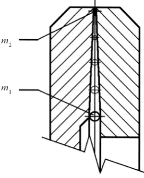
After the grist enters between the active surfaces of the discs, this force generates the tangential, cen-trifugal and Coriolis forces, and their reactions: fric-tion forces, the destructive (disintegrafric-tion) power and the inertia force (Feynman et al. 2011) (Fig 1).
The problem associated with monitoring the status and behaviour of selected particles (single grains) is complicated by the ever-shrinking char-acteristic dimension (and thus its mass, i.e. changes
m1 on m2), which runs from the input radius to the output from the grinding surfaces.
Trajectories of the gradually separated particles of the processed grain are formed under the effect of the above mentioned forces which can be de-fined as follows (Feynman et al. 2011):
Fn=rM
mean
(N) (2)
where:
Fn – perpendicular force created by the disc station (N) M – driving torque for the actual grinding (N.m) rmean – mean radius of the active part of a disc (m)
The tangential force is a projection of the force Fn to the tangent of the trajectory curve in the moni-tored point:
Fγ= Fn cos π
2− γ ⎛ ⎝⎜ ⎞⎠⎟
(N) (3)
where:
Fn – perpendicular force created by the disc station (N) Fγ – resultant effect of perpendicular and centrifugal
forces acting on the curve track (N)
γ – angle between the curve tangent and the vector at a point (°)
Centrifugal force Fo, with which the fragments mass m reduces along the trajectory s:
Fo = m × r × ω (N) (4) where:
Fo – centrifugal force (N) m – particle mass (kg) r – radius forces (m)
ω – angular velocity of the rotating disk (1/s)
Angular velocity of the rotating disk speed ω for n = const. and ω = const.:
ω = 2π × n (1/s) (5) where:
ω – angular velocity of the rotating disk (1/s) n – frequency of rotation (1/s)
Due to its orientation, the Coriolis force FC caus-es an additional component of friction T:
FC = 2m × ω × vrel (N) (6) where:
[image:2.595.90.232.550.725.2]FC – Coriolis force (N) m – particle mass (kg) Fig. 1. Movement of particles (fragments) – cross section
m1 – initial mass of particle (kg), m2 – final mass of particle (kg) m1
ω – angular velocity of the rotating disk (1/s)
vrel – relative (secondary) speed of a fragment along the vector from the entry to the periphery (m/s)
Friction force:
T = N × f (N) (7) where:
T – friction force (N) N – perpendicular force (N)
f – coefficient of grist friction on the surface of discs (–)
TC= FC × f = 2m × ω × vrel (N) (8) where:
TC – supplementary component of fiction force, i.e. fric-tion force due to Coriolis force (N)
FC – Coriolis force (N)
f – coefficient of grist friction on the surface of discs (–) m – particle mass (kg)
ω – angular velocity of the rotating disc (1/s)
vrel – relative (secondary) speed of a fragment along the vector from the entry to the periphery (m/s)
The destructive force is defined using the follow-ing equation:
Fdest = τdest × S (N) (9) where:
Fdest – destruction force (N)
τdest – destructive tension between the shear strengths of grain (Pa)
S – cross section of grain: kx2 (m2)
For the inertia force FSthe following equation is valid:
FS =m×aγ=m×dvγ
dt (N) (10)
where:
FS – inertial force (N) m – particle mass (kg)
aγ – tangential acceleration (m/s2)
vγ – tangential velocity of a grist fragment along a trajec-tory formed by a logarithmic spiral trajectrajec-tory (m/s) t – time (s)
The force of gravity G or its surface effects are ig-nored here, due to the orientation of the axis of rota-tion in the horizontal posirota-tion. The strength of gravity (its components) in the upper halves of the discs acts against the grist leaving the grinding surfaces of discs:
G = m × g (N) (11) where:
G – gravitation force (N) m – particle mass (kg)
g – acceleration due to gravity (m/s2)
In the lower half an opposite phenomenon occurs. It is obvious that the forces exerted in the vertical plane cancel each other, thus creating an asymmetry of forces and moments relative to the axis of rotation.
In general, the above can be expressed by this vector relationship (Simmons 1996; Guzman 2003; Feynman at al. 2011):
Fn + Fo + Fdest – FS – T –TC = 0 (N) (12) where:
Fn – perpendicular force created by the disc station (N) Fo – centrifugal force (N)
Fdest – destruction force (N) FS – inertial force (N) T – friction force (N)
TC – supplementary component of fiction force, i.e. friction force due to Coriolis force (N)
On the curve trajectory s the perpendicular force Fn acts together with the centrifugal force Fo. This results in a joint Fγ lying on a tangent to the trajec-tory of the curve, which is followed by a fragment of grist during the grinding process. This happens only on the curve which always forms a constant angle with its vectors.
The friction force T increases with the degree of the particles separation between the discs because the perpendicular force N (pressure on the active edges of discs) increases. This is caused by the total volume of the fragments always being greater than the volume of the original particle (grain).
An additional component of the friction force TC arises from the Coriolis acceleration orientation, which operates within the meaning of the drifting movement. The destructive force Fdest is directly proportional to the transverse cross-section of the particle (fragment), which also decreases in size proportionally along the trajectory.
Fig. 2 also outlines the aspects of the kinematic motion of fragments along the curve’s path.
Generally, the vector relation holds:
vγ = vo + vrel (m/s) (13) where:
vo – peripheral speed (m/s)
vrel – relative (secondary) speed of a fragment along the vector from the entry to the periphery (m/s)
where the following is valid for the circumferential velocity:
vo= rmean × ω (m/s) (14) where:
vo – peripheral speed (m/s)
rmean – mean radius of the active part of a disc (m) ω – angular velocity of the rotating disk (1/s)
The outlined analysis of the forces and the speed (acceleration) of the particles (Fig. 2) is based on the assumption of their movement along the tan-gents which form a constant angle with the vectors of the curve (the path trajectory). This curve, whose radius r grows exponentially as the angle increases, is the logarithmic spiral.
The logarithmic spiral, being a trajectory of the fragments pulverized on the active surfaces of the disc crushers, has the following basic properties. The spiral winds around a fixed point. Polar
co-ordinates, in which the pole O and the polar axis x provide the base, are used for its analytical for-mulation. Each its point in the plane is determined by vector r, i.e. by the distance of a point from the pole and by the angle ϕ, which is the vector’s
devia-tion from the polar axis (Simmons 1996; Guzman 2003; Banchoff, Lovett 2010).
The logarithmic spiral is defined by the polar (Toriccelli) equation (Holliday-Darr 1998; Guz-man 2003; Banchoff, Lovett 2010):
r = a × ebϕ (15)
where:
r – logarithmic spiral vector length, i.e. distance of a point from the pole (m)
a, b – logarithmic spiral constants (–) e – base of natural logarithms (–)
ϕ – angle which is a deviation of a vector from the
polar axis (°)
It is also true that: r2
r1
=a×ebϕ2
a×ebϕ1 =eb
[image:4.595.106.512.89.292.2]ϕ (16)
Fig. 2. Action of forces and kinematics of disc grinding
Fdest – destruction force (N), FN – perpendicular force created by the disc station (N), Fo – centrifugal force (N), FS – inertial force (N), Fγ –resultant effect of perpendicular and centrifugal forces acting on the curve track (N), G – gravitation force (N), N – perpendicular force (N), T – friction force (N), TC – supplementary component of fiction force, i.e. friction force due to Coriolis force (N), g – acceleration due to gravity (m/s2), h – grinding joint (mm), m – particle mass (kg), r
mean – mean radius
of the active part of a disc (m), vγ – tangential velocity of a grist fragment along a trajectory formed by a logarithmic spiral trajectory (m/s), vo – peripheral speed (m/s), vrel – relative (secondary) speed of a fragment along the vector from the entry to the periphery (m/s), x – characteristic size of a particle (fragment) (m), γ– the angle between the curve tangent and the vector at a point (°), τdest – destructive tension between the shear strengths of grain (Pa), ω – angular velocity of the rotating disk (1/s)
where:
r1, r2 – vectors of a logarithmic spiral, i.e. of the dis-tance of a point from the pole (m)
a, b – logarithmic spiral constants (–) e – base of natural logarithms (–)
ϕ1,ϕ2 – angles which is a deviation of a vector from the
polar axis (°)
For the construction of a logarithmic spiral (Ta-ble 1) it is necessary to define the above mentioned constants a and b, where a determines the begin-ning of the spiral and b causes the change in the radius (length) of the spiral. The rp vector lengths form a geometric sequence:
an = a1 × qn–1 (17)
where:
a – logarithmic spiral constants (–)
n – n-th member of geometric sequence (–) q – quotient of geometric sequence (–)
The following is valid for the tangent angle γ, formed by a vector and a tangent for a given point (rp; φ):
tgγ= drr dϕ
and thus γ=arctg drr
dϕ
=arctg 1
b
(18 and 19) For
b → 0 is
Fn=rM
mean
Fγ= Fn
cos⎛⎝⎜π2− γ⎞⎠⎟
FS=m×aγ=m×
dvγ
dt
r2
r1
=a×eb× ϕ2 a×eb× ϕ1=eb
× ϕ
tgγ= drr dϕ
γ=arctg drr
dϕ
=arctg 1
b ∞ → b 1 arctg 1
b→ π2
dr
dϕ=a×b×eb× ϕ=b×r
s= (x)2+(y)2 0
ϑ
∫
dt2
2 ( )
) (x + y
and arctg 1
b→ π2 (20–22)
where:
γ – angle between the curve tangent and the vector at a point (°)
r – logarithmic spiral vector length, i.e. distance of a point from the pole (m)
ϕ – angles which is a deviation of a vector from the
polar axis (°)
b – logarithmic spiral constants (–)
π – spiral shape is therefore approaching a circle
The tangent angle γ is at each point of a given spi-ral the same, because the parameter b is constant.
The total length of the spiral s is finite and it changes in a computing relationship with a b ex-ponent, that is, exponentially, with the constant
parameter a determining the distance of the begin-ning of the spiral from its pole.
A logarithmic spiral equation expressed para-metrically:
x = r × cos t = a × ebt × cos t (23) y = r × sin t = a × ebt × sin t (24) where:
x, y, t – parameters of the logarithmic spiral (–)
r – logarithmic spiral vector length, i.e. distance of a point from the pole (m)
a, b – logarithmic spiral constants (–) e – base of natural logarithms (–)
The change in the radius (length) of the spiral is expressed by the derivation:
dr
dϕ=a×b×eb
ϕ=b×r
(25 and 26)
where:
r – logarithmic spiral vector length, i.e. distance of a point from the pole (m)
ϕ – angle which is a deviation of a vector from the
polar axis (°)
a, b – logarithmic spiral constants (–) e – base of natural logarithms (–)
The length of the logarithmic spiral can be deter-mined when we choose any point A at a distance rp from the spiral’s pole, whose position is given by the polar coordinates r and υ. The length of the spi-ral is determined from its beginning to the point A by using the relationship (Guzman 2003; Ban-choff, Lovett 2010):
s= (x)2+(y)2 0
ϑ
∫
dt (27)where:
s – length of a logarithmic spiral (m)
x, y, t – parameters of the logarithmic spiral (–)
by integration over the entire curve.
If we consider the parameter t to be time then
[image:5.595.63.533.103.138.2](x)2+(y)2
Table 1. The total length per unit of the logarithmic spiral s with the changing exponent b
b (–) 0.1 0.2 0.3 0.4 0.5 0.6 0.7 0.8 0.9 1.0
expresses the size of the instantaneous velocity of the movement and it is therefore possible to state:
s= v(t)dt
α β
∫
(28)where:
s – length of a logarithmic spiral (m)
α, β – angles defining the points of a logarithmic spiral in determining its length (°)
v – instantaneous velocity (m/s) t – time (s)
First, the derivation of parametric equations has to be stipulated:
x=a×b×ebt×cost−a×ebt×sint
(29)
y=a×b×ebt×sint+a×ebt×cost
(30) where:
x, y, t – parameters of the logarithmic spiral (–) a, b – logarithmic spiral constants (–) e – base of natural logarithms (–)
then the following has to be calculated
(x)2+(y)2=(a×b×ebt)2+(a×ebt)2=a2×e2bt×(b2+1)
(31) where:
x, y, t – parameters of the logarithmic spiral (–) a, b – logarithmic spiral constants (–) e – base of natural logarithms (–)
RESULTS AND DISCUSSION
In general, the following applies for the length of the element of the curve:
(ds)2 = (dx)2 + (dy)2 (32)
where:
s – length of a logarithmic spiral (m)
x, y – parameters of the logarithmic spiral (–)
Therefore, after substitution it will be:
(ds)2=⎡⎣(x)2+(y)2⎤⎦(dt)2
(33) where:
s – length of a logarithmic spiral (m)
x, y, t – parameters of the logarithmic spiral (–)
and then the differential of the arc of the curve will be given by the relationship:
ds= (x)2+(y)2 dt
(34) where:
s – length of a logarithmic spiral (m)
x, y, t – parameters of the logarithmic spiral (–)
And the total length will be determined by in-tegration over the entire logarithmic curve, as al-ready shown above (Guzman 2003; Banchoff, Lovett 2010):
s= (x)2+(y)2 dt 0
ϑ
∫
= a×ebt (b2+1)0
ϑ
∫
dt=a×ebϑ × b2+1b =
b2+1
b ×r
(35 and 36)
where:
s – length of a logarithmic spiral (m)
x, y, t – parameters of the logarithmic spiral (–) e – base of natural logarithms (–)
r – logarithmic spiral vector length, i.e. distance of a point from the pole (m)
Increasing the efficiency of separating processes still appears to be an ongoing task. Theoretical anal-ysis of energy requirements of disintegration pro-cesses must continue to be verified experimentally. Experiments carried out on the machines used in factory plants cannot provide sufficiently accurate and therefore reproducible results. The presented theory of motion of particles and their fragments on active disc surfaces and the resulting relation-ships and conclusions have already been prelimi-narily confronted with laboratory experiments. For this purpose, a measuring apparatus capable of determining the relationships between the above described variables with very good accuracy was assembled in the laboratory of the Department of Technological Equipment of Buildings, Technical Faculty, Czech University of Life Sciences Prague, using an upgraded test stations dynamometer DS 546-4 /V (MEZ a.s., Vsetín, Czech Republic).
CONCLUSION
So far, the measurements and obtained partial results have provided preliminary confirmation of the good efficiency of the separating shear process that takes place in disc mills and also have indicat-ed a corresponding agreement with the presentindicat-ed theoretical assumptions. A more detailed presenta-s= (x)2+(y)2 dt
0
ϑ
∫
= a×ebt (b2+1) 0ϑ
∫
dt=a×ebϑ × b2+1b = b
2+1
tion of the results of laboratory experiments car-ried out so far on disc machines is beyond the in-tended scope intention of the authors, as conceived in this publication.
References
Banchoff F.T., Lovett T.S., 2013. Differential Geometry of Curves and Surfaces. Wellesley, A.K. Peters Ltd.: 200. Feynman R.P., Leighton B.R., Sands M., 2011. The
Feyn-man Lectures on Physics, Boxed Set: The New Millennium Edition. 1st Ed. New York, Basic Books: 552.
Guzman A., 2003. Derivatives and Integrals of Multivariable Functions. 1st Ed. Boston, Birkhäuser: 329.
Holliday-Darr K.A., 1998. Applied Descriptive Geometry. 2nd Ed. Independence, Delmar Cengage Learning: 416.
Simmons G., 1996. Calculus With Analytic Geometry. 2nd Ed.
McGraw-Hill Science/Engineering/Math: 887.
Zueva G.A., Padokhin V.A., Ditl P., 2010. Stochastic mod-els of solid particles grinding. Acta Polytechnica, 50: 70–75.
Received for publication May 25, 2012 Accepted after corrections December 10, 2012
Corresponding author:
Ing. Petr Vaculík, Ph.D., Czech University of Life Sciences Prague, Faculty of Engineering,