Effects of Substrate Temperature and Oxygen Pressure
on Crystallographic Orientations of Sputtered Nickel Oxide Films
Hao-Long Chen
1;*, Yang-Ming Lu
2, Jun-Yi Wu
2and Weng-Sing Hwang
11
Department of Materials Science and Engineering, National Cheng Kung University, Tainan, Taiwan 70101 R. O. China
2Department of Electronics Engineering & Nano Technology Research and Development Center, Kun Shan University of Technology,
Yung-Kang City, Tainan Hsien, 71003 Taiwan, R. O. China
Nickel oxide (NiO) films with NaCl-type structure were deposited onto Corning glass substrates at different substrate temperatures by radio-frequency (RF) magnetron sputtering under an RF power of 200 W. The resulting films were analyzed by grazing-incidence X-ray diffraction, ultrahigh resolution scanning electron microscopy (HR-SEM) and high-resolution transmission electron microscopy (HR-TEM). The relationships among the gas ratio of O2, substrate temperature, preferred orientation and microstructure of the NiO films were investigated.
Those films deposited at a substrate temperatures of 303 or 473 K with the ratio of oxygen varying from 0 to 100% displayed a (111) preferred orientation. At the substrate temperature of 673 K, while the (111)-orientated film was obtained under a low ratio of oxygen (<50% O2), a (200)
preferred orientation was developed under 100% oxygen. All the films have a columnar structure with the growth direction perpendicular to the surface. The origin of the preferred orientations is also discussed.
(Received April 25, 2005; Accepted September 26, 2005; Published November 15, 2005)
Keywords: nickel oxide, reactive sputtering, crystallographic orientation
1. Introduction
Nickel oxide (NiO) thin films with NaCl-type structure have recently drawn considerable attention because they are important in several scientific and technological applications. They exhibit excellent chemical stability, as well as optical, electrical and magnetic properties. They have been employed as an antiferromagnetic material,1) p-type transparent
con-ducting films,2) a material for electrochromic display
de-vices,3) and a part of functional sensor layers in chemical
sensors.4)Furthermore, (100)- and (111)-oriented NiO films
can be used as buffer layers that are deposited on oxide films with other orientations, such as c-axis-oriented perovskite-type ferromagnetic films and superconducting films,5–7)
because they are chemically stable and the oxygen ion lattice constant of NiO is similar to that of the oriented oxide films. Such films have been fabricated using various physical and chemical vapor deposition techniques, including spray pyrolysis,8,9) electron beam evaporation,10) pulsed laser deposition,11) plasma-enhanced chemical vapor deposi-tion1,12)and reactive sputtering.3,13,14)Reactive sputtering is the most widely used among these methods. The dependence of film properties on sputtering parameters has been studied extensively.12,15–18) Many reference data and studies12,15–18)
have indicated that superior electric and optical properties of NiO films can be obtained by reactive sputtering in a pure oxygen atmosphere in the range 0.1–1 Pa and using a heated substrate.
Controlling the crystallographic orientation and surface roughness of the films is very important in using NiO films as buffer layers. Fujiiet al.1)have prepared NaCl-type NiO films
on glass substrates at 673 K using plasma-enhanced metal organic chemical vapor deposition (PE-MOCVD). The (111) and (100) preferred orientations of NiO films were controlled by changing oxygen flow rates. Sato et al.2) have also
reported that NiO thin films deposited in an atmosphere with an oxygen content of over 20% by RF magnetron sputtering yielded two weak diffraction peaks from the (111) and the (200) planes. Wanget al.9)have prepared NiO nanosize thin films with a (200) preferred orientation on Si(111) substrates by pulsed ultrasonic spray pyrolysis. Ryu et al.14) have observed that the NiO films deposited on Si(100) substrates at room temperature with different ratios of oxygen to argon in the atmosphere by RF magnetron sputtering were (100)-oriented in a pure argon atmosphere while (111)-(100)-oriented in an oxygen atmosphere. Kang et al.19) have prepared NiO
films using nickel dicyclopentadienyl with oxygen at various temperatures and different oxygen flow rates by chemical vapor deposition. The (111)-orientated NiO films were formed at low deposition temperatures (<548K), while the (100)-orientated NiO films were formed at high deposition temperatures (>548K). Other researchers have observed this variation of orientation from (111) to (100) with the increase in the substrate temperature for other metallic oxide films (TiO2, ZnO and In2O3:SnO2) prepared by reactive magnetron sputtering.20–22)In this work, the (100)- and (111)-oriented NiO films with a thickness of approximately 200 nm were grown on Corning 1737 glass substrates by reactive radio-frequency (RF) magnetron sputtering under various ratio of oxygen to argon in the atmosphere. The effect of substrate temperature on the crystallographic orientation and microstructure of the films are described, and the origin of the preferred orientation is discussed as follows.
2. Experimental Methods
Nickel oxide films were deposited on a Corning 1737 using a 0.7 mm thick glass substrate by RF magnetron sputtering from an NiO target with a purity of 99.99%. The ratio of oxygen to argon for the sputtering gases was set at either 0, 50 or 100%. The distance between the target and the substrate was approximately 80–85 mm. Then the chamber was *Corresponding author, E-mail: [email protected]
evacuated to a pressure of under 4104Pa before deposition. Sputtering deposition was subsequently per-formed under a gas pressure of 1 Pa while the RF power was maintained constant at 200 W. The substrate was kept at a temperature ranging from 303 to 673 K and the thickness of the films was about 200 nm. A conventional stylus surface-roughness detector (Alpha-step 200) was used to measure the thickness of the films. Then the crystal structure of the deposited films was identified by grazing-incidence X-ray diffraction (GIXRD) using a Rigaku D/MAX 2500 multi-purpose X-ray thin film diffractometer with monochromatic high-intensity CuK radiation ( ¼0:15418nm). The mi-crostructure was observed using ultrahigh resolution trans-mission electron microscope (HR-AEM, Hitachi model HF-2000 field-emission transmission electron microscope) and FEG-TEM (Philips Tecnai F30 Field Emission Gun Trans-mission Microscope). The surface morphology was observed using a ultrahigh resolution scanning electron microscope (HR-SEM, Hitachi S4100). Finally, the chemical composi-tions of the films were examined by X-ray photoelectron spectroscopy (XPS) using a VG ESCA210 electron spectro-scope.
3. Results and Discussion
The crystal structure of the as-deposited NiO film was identified to be polycrystalline. The thicknesses of the films under investigation were consistently around 200 nm. The X-ray diffraction patterns of the films deposited at the substrate temperature from 303 to 673 K with the ratio of 100% O2 are shown in Fig. 1. The diffraction peaks were identified and compared with those of the standard 2 theta peaks on a JCPDS card (Bunsenite, NaCl-type structure, 2003 JCPDS database No. 89-7130). The films exhibited a (111) preferred orientation at a low substrate temperature (303 K). The preferred orientation gradually changed from (111) to (200) as the substrate temperature increased. Finally, the films exhibited a (200) preferred orientation when the substrate temperature reached 673 K.
The preferred orientation of a particular crystal plane of polycrystalline film can be expressed as.23)
TCðhklÞ ¼
IðhklÞ
IoðhklÞ 1
N
P IðhklÞ
IoðhklÞ
ð1Þ
whereTCðhklÞis the texture coefficient of the specific (hkl) plane;IðhklÞis the measured intensity;IoðhklÞis the relative intensity factor taken from the 2003 JCPDS database No. 89-7130, and N is the number of XRD peaks considered. The reflections from the (111), (200) and (220) planes were observed in all films. Therefore, the variation of texture coefficient (TC) can be used to demonstrate the effect of substrate temperature on preferred orientation. TheTCvalue is unity when the crystal orientation is random and no preferred orientation exists. The TC value exceeds unity when the film has a preferred orientation and most of its grains are orientated in the same direction with their (hkl) planes parallel to the film surface.
Figure 2 shows the TC variation with substrate temper-ature. It can be seen that theTC(111) decreases from 1.79 to 0.24 as the substrate temperature increases from 303 to 673 K. Conversely, theTC (200) changes from 0.08 to 2.33 while TC (220) gradually decreases from 1.03 to 0.43. The films deposited at low deposition temperatures (<473K) exhibit a (111) preferred orientation while at high deposition temperatures (>473K), they exhibit a (200) preferred orientation.
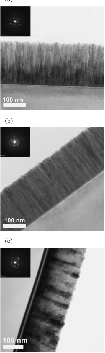
Figure 3 shows SEM micrographs of the surfaces and Fig. 4 shows TEM micrographs of the cross sections. All the films exhibit a columnar structure with the growth direction perpendicular to the surface. Previous reports1,2,9,14,19)have
suggested that the NiO film texture depends on both the oxygen content in the film and the deposition temperature. Figure 5 shows results of a quantitative XPS analysis of the films deposited at different substrate temperatures. The oxygen content is linearly decreased from 49 to 47 at% while the nickel content is increased from 51 to 53 at% as the substrate temperature is increased from 303 to 673 K.
Figure 6(a) shows X-ray diffraction patterns of the films deposited at the substrate temperature of 303 K with different
Fig. 1 X-ray diffraction patterns of NiO films deposited at different substrate temperatures in an atmosphere of pure oxygen (100% O2).
[image:2.595.54.281.573.758.2] [image:2.595.311.540.574.757.2]ratios of oxygen to argon. The film deposited in pure argon atmosphere shows (111) and (200) peaks while the films deposited in different fractions of oxygen show (111), (220) and (311) peaks. The peak intensity of (111) increases with
an increasing ratio of oxygen. Figure 6(b) shows patterns from films deposited at a substrate temperature of 673 K with different fractions of oxygen to argon. The films deposited in Ar (0% O2) and 50% O2 show dominating (111) peak.
(a)
(b)
(c)
Fig. 3 Scanning electron micrographs of NiO films prepared at different substrate temperatures: (a) 303 K, (b) 473 K, (c) 673 K.
(a)
(b)
(c)
[image:3.595.58.277.76.682.2] [image:3.595.338.516.81.677.2]However, as the fraction of oxygen increases to 100%, the preferred orientation is changed from (111) to (200).
[image:4.595.54.283.73.254.2]The variation of the texture coefficient (TC), as shown in
Fig. 7, represents the effect of substrate temperature and ratio of oxygen to argon on the preferred orientation. At 303 K, the
TC(111) slightly changes from 1.71 to 1.90 when the ratio of oxygen to argon increases while theTC(200) decreases from 0.76 to 0.08. At 673 K, theTC(111) initially increases from 1.59 to 2.08 when the ratio of oxygen to argon increases from 0 to 50%. However, TC(111) abruptly drops to 0.24 while
TC(200) increases from 0.68 to 2.33 under the ratio of 100% O2. Therefore, a (200) preferred orientation is developed at the deposition temperature of 673 K with 100% O2.
The variation of the crystallographic orientation against substrate temperature and sputtering gas can be reasoned as follows.
The crystal orientation of the film is controlled by the nucleation and growth of the grains.23)The crystallographic orientations of NiO films are affected by the arrangement of O2 under the pure oxygen atmosphere at low substrate temperatures (<473K) and the low ratio of oxygen (<50% O2) at a deposition temperature of 673 K. Ni2þ and O2,
Fig. 5 Compositions of NiO films deposited at different substrate temper-atures determined by Quantitative XPS analysis.
(a)
(b)
Fig. 6 X-ray diffraction patterns of NiO films deposited at substrate temperatures of (a) 303 K and (b) 673 K with different ratios of O2to Ar.
(a)
(b)
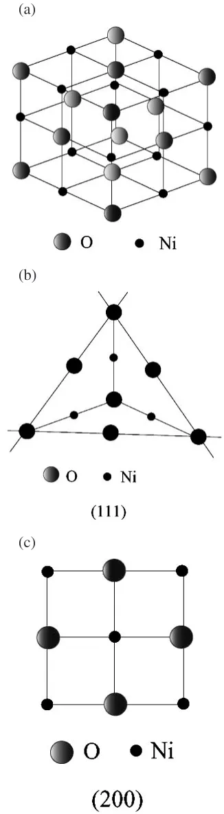
[image:4.595.311.541.75.497.2] [image:4.595.53.285.300.702.2]which are produced by sputtering process, collide separately onto the growing film surface.1)The radius of O2(0.140 nm) is larger than that of Ni2þ (0.069 nm). In order to minimize the surface energy of the growing NiO film, O2 must be arranged in the most densely packed plane; (111), as shown in Fig. 8(b). Therefore, the preferred orientation is (111) under the pure oxygen atmosphere at low substrate temper-atures (<473K) and the low ratio of oxygen (<50% O2) at a high substrate temperature of 673 K. However, under pure oxygen atmosphere at a high deposition temperature of 673 K, Ni2þand O2collide onto the growing NiO film at the same time. They are then arranged in the (100) plane in order to minimize the surface energy as shown in Fig. 8(c). Therefore, the preferred orientation is (100) under pure oxygen atmosphere at a high substrate temperature of 673 K. As suggested by Ventrice, Jr., repulsive forces exerted between oxygen ions and electrostatic energy of Ni–O pairs significantly contributes to the formation of NiO.24) The
surfaces of any ionic or partly ionic crystal have been identified by Tasker25)as type I, II, or III. In type I surfaces,
the stacking plane is neutral and composed of both anions and cations at a stoichiometric ratio, resulting in no dipole perpendicular to the surface. Type II surfaces contain a series of charged planes. They make a symmetric repeat unit that has no net dipole perpendicular to the surface. Type III charged surfaces have a dipole moment in the repeat unit perpendicular to the surface.26)
When the NiO film is deposited under the low temperature or the low ratio of oxygen at high temperature, Ni2þand O2 collide separately onto the growing film surface and not enough energy or oxygen is provided for the Ni2þand O2to recombine. It is more likely for the film to be formed with non-stoichiometric ratio, which is electrostatically polar. According to Fisher,27)the surface of the (111) crystal plane
of NiO is a Type III surface in Tasker’s scheme.25)It can then
be understood that (111) will be the preferred orientation under the low sputtering temperature or the low ratio of oxygen at high temperature.
When the NiO film is deposited under high temperature, Ni2þand O2collide onto the growing NiO film at the same time. It is more likely for the film to be formed with stoichiometric ratio, which is electrostatically neutral. Ac-cording to Fisher,27)the surface of the (200) crystal plane of NiO is a Type I surface in Tasker’s scheme.25)It can then be understood that (200) will be the preferred orientation under the high sputtering temperature.
In this study, the (111) oriented NiO films were developed at different deposition temperatures with different ratios of oxygen to argon. As an exception, the (200)-oriented NiO films were formed at the deposition temperature of 673 K and under the ratio of 100% O2. These results are in accordance with the deduction discussed above.
4. Conclusion
The nickel oxide (NiO) films were deposited at different deposition temperatures with different ratios of oxygen to argon by radio-frequency (RF) magnetron sputtering under an RF power of 200 W. Those films deposited at a substrate temperature of 303 and 473 K, respectively, with a ratio of
oxygen ranging from 0 to 100%, has displayed a (111) preferred orientation. For films deposited at substrate temper-ature of 673 K, the (111)-orientated NiO film was obtained under a low ratio of oxygen (<50% O2), the (200) preferred orientation was developed under a ratio of 100% oxygen. The
(a)
(b)
(c)
[image:5.595.343.506.73.665.2]cross section of TEM micrographs indicated the NiO films had a columnar structure perpendicular to the surface of the NiO film.
Acknowledgments
The authors would like to thank the National Science Council of Taiwan for financially supporting this research under Contract No. 2216-E-006-013 & NSC93-2216-E-168-006.
REFERENCES
1) E. Fujii, A. Tomozawa, H. Torii and R. Takayama: Jpn. J. Appl. Phys. 35(1996) L328–L330.
2) H. Sato, T. Minami, S. Takata and T. Yamada: Thin Solid Films236 (1993) 27–31.
3) M. Kitao, K. Izawa, K. Urabe, T. Komatsu, S. Kuwano and S. Yamada: Jpn. J. Appl. Phys.33(1994) 6656–6662.
4) H. Kumagai, M. Matsumoto, K. Toyoda and M. Obara: J. Mater. Sci. Lett.15(1996) 1081–1083.
5) J. Yang, D. Q. Shi, C. Park, K. J. Song, R. K. Ko, H. Z. Liu and H. W. Gu: Physica C412–414(2004) 844–847.
6) T. Maeda, S. B. Kim, T. Suga, H. Kurosaki, Y. Toyotaka, Y. Yamada, T. Watanabe, K. Matsumoto and I. Hirabayashi: Physica C357–360 (2001) 1042–1045.
7) S. S. Lee, D. G. Hwang, C. M. Park and J. R. Rhee: J. Appl. Phys.81 (1997) 5298–5300.
8) P. Puspharajah, S. Radhakrishna and A. K. Arof: J. Mater. Sci.32 (1997) 3001–3006.
9) S. Y. Wang, Wei Wang, W. Z. Wang and Y. W. Du: Mater. Sci. Eng. B 90(2002) 133–137.
10) A. Agrawal, H. R. Habibi, R. K. Agrawal, J. P. Cronin, D. M. Roberts, C. P. R’Sue and C. M. Lampert: Thin Solid Film221(1992) 239–253. 11) M. Tanaka, M. Mukai, Y. Fujimori, M. Kondoh, Y. Tasaka, H. Baba
and S. Usami: Thin Solid Films281–282(1996) 453–456.
12) E. Fujii, A. Tomozawa, S. Fujii, H. Torii, M. Hattori and R. Takayama: Jpn. J. Appl. Phys.32(1993) L1448–L1450.
13) H. Matsueda and B. L. Averbach: Mater. Sci. Eng.23(1976) 131–134. 14) H. W. Ryu, G. P. Choi, W. S. Lee and J. S. Park: J. Mater. Sci. Lett.39
(2004) 4375–4377.
15) O. Kohmoto, H. Nakagawa, F. Ono and A. Chayahara: J. Magn. Magn. Mater.226–230(2001) 1627–1630.
16) Y. M. Lu, W. S. Hwang and J. S. Yang: Surf. Coat. Technol.155(2002) 231–235.
17) Y. M. Lu, W. S. Hwang, J. S. Yang and H. C. Chuang: Thin Solid Films 420–421(2002) 54–61.
18) I. Hotovy´, J. Huran, L. Spiess, J. Liday, H. Sitter and Sˇ. Hasˇcˇı´k: Vacuum69(2003) 237–242.
19) J. K. Kang and S. W. Rhee: Thin Solid Films391(2001) 57–61. 20) L. J. Meng, M. Andritschky and M. P. dos Santos: Thin Solid Films223
(1993) 242–247.
21) L. J. Meng, M. Andritschky and M. P. dos Santos: Vacuum45(1994) 19–22.
22) L. J. Meng and M. P. dos Santos: Thin Solid Films322(1998) 56–62. 23) D. Walton: Philos. Mag.7(1962) 1671–1679.
24) C. A. Ventrice, Jr., Th. Betrams, H. Hannemann, A. Brodde and H. Neddermeyer: Phys. Rev. B49(1994) 5773–5776.
25) P. W. Tasker: J. Phys. C: Solid State Phys.12(1979) 4977–4984. 26) P. M. Oliver, G. W. Watson and S. C. Parker: Phys. Rev. B52(1995)
5323–5329.