© 2019, IRJET | Impact Factor value: 7.211 | ISO 9001:2008 Certified Journal | Page 6910
Design and Fabrication of Air breathing Solid Oxide Fuel Cell and its
performance testing using Hydrogen gas
1
V. Savithiri,
2R. Pradeep,
3K. Praveen Krishna
1Department of Mechanical Engineering, St. Joseph’s Institute of Technology, Chennai-600119, Kanchipuram
District, Tamilnadu, India.
Email: [email protected], Contact Number: +91944987557, *Corresponding Author
2Department of Mechanical Engineering, St. Joseph’s Institute of Technology, Chennai-600119, Kanchipuram
District, Tamilnadu, India.
Email: [email protected], Contact Number: +919176851973
3Department of Mechanical Engineering, St. Joseph’s Institute of Technology, Chennai-600119, Kanchipuram
District, Tamilnadu, India.
Email: [email protected], Contact Number: +918939306730
ABSTRACT - The main objective of this project is to
produce power by solid oxide fuel cell. The reason for this alternative means of power producing is to eliminate the over exploitation of fossil fuels. By the availability of Hydrogen, which is abundantly present across the globe it is easier to supply fuel for power generation. The main benefit of opting for SOFC is that its ability to intake various Hydrocarbons in their gaseous gas as fuel. Solid oxide fuel cell (SOFC) is an electrochemical device, based on an oxide ion conducting electrolyte, which converts chemical energy of a fuel (such as hydrogen or a hydrocarbon) into electricity at temperatures from about 550o to 1000o C. SOFC offers certain advantages over lower temperature fuel cells, notably its ability to use CO as fuel rather than being poisoned by it, and high grade exhaust heat for combined heat and power, or for combined cycle gas turbine applications.
Keywords- SOFC, energy, hydrogen, Voltage, air-breathing.
1.INTRODUCTION
A fuel cell is an electrochemical device that converts the chemical energy of a reaction (between fuel and oxidant) directly into electrical energy. The basic physical structure, or building block, of a fuel cell
consists of an electrolyte layer in contact with a porous anode and cathode on either side. In a typical fuel cell, gaseous fuels are fed continuously to the anode (negative electrode) and an oxidant (i.e. oxygen from air) is fed continuously to the cathode (positive electrode) The electrochemical reactions take place at the electrodes to produce an electric current. A fuel cell should not be confused with secondary batteries (accumulators). The battery (primary) is an energy storage device. The maximum energy available is determined by the amount of chemical reactant stored within the battery itself. The battery will cease to produce electrical energy when the chemical reactants are consumed (i.e. discharged). In a secondary battery, the reactants are regenerated by recharging, which involves putting energy into the battery from an external (electricity) source. The fuel cell, on the other hand, is an energy conversion device that theoretically has the capability of producing electrical energy for as long as fuel and oxidant are supplied to the electrodes.
2. LITERATURE SURVEY
© 2019, IRJET | Impact Factor value: 7.211 | ISO 9001:2008 Certified Journal | Page 6911 used directly, through internal reforming or even
direct oxidation. This provides a key entry strategy for fuel-cell technology into the current energy economy. Present development is mainly based on the yttria-stabilized zirconia (YSZ) electrolyte. The most commonly used anode materials are Ni/YSZ cermets, which display excellent catalytic properties for fuel oxidation and good current collection, but do exhibit disadvantages, such as low tolerance to sulphur and carbon deposition when using hydrocarbon fuels, and poor redox cycling causing volume instability. Here, we report a nickel-free SOFC anode, La0.75Sr0.25Cr0.5Mn0.5O3, with comparable electrochemical performance to Ni/YSZ cermets. The electrode polarization resistance approaches 0.2 Ω cm2 at 900 °C in 97% H2/3% H2O. Very good performance is achieved for methane oxidation without using excess steam. The anode is stable in both fuel and air conditions, and shows stable electrode performance in methane. Thus both redox stability and operation in low steam hydrocarbons have been demonstrated, overcoming two of the major limitations of the current generation of nickel zirconia cermet SOFC anodes.
3. MATERIALS
3.1 NICKEL OXIDE
Nickel Oxide is the most common anode catalyst, and its low cost has led to its wide usage. It has a high electronic conductivity and a low ionic conductivity, making it necessary to employ a Ni/YSZ mixture in the anode to increase the triple phase boundary area conducive for electrochemical reactions. Further a NiO/YSZ mix improves adhesion of the anode to the YSZ electrolyte as the coefficients of thermal expansion are in close order compared to pure nickel.
3.1 YITTRIUM STABILIZED ZIRCONIA
Yttria stabilized zirconia is mainly used for the electrolyte due to its ability to Conduct oxide ions and also in the anode as the electrolyte component along with an electronic conductor to induce mixed ionic electronic conduction (MIEC) properties. YSZ is
a ceramic material, and its oxide ion conducting properties are prominent in a temperature range of 600o C to 1000°C
3.2 LANTHANUM STRONTIUM MANGANITE
Lanthanum strontium manganite is the most common cathode catalyst in today’s SOFCs and is often known to be employed as a composite cathode with the electrolyte component YSZ. It is reported that thin LSM electrodes display low MIEC properties as a result of reduction in resistance to oxygen ion transport. Yang et al. experimentally found that LSM/YSZ composites sintered at 1400°C for 12 hours formed an insulating lanthanum zirconate layer (La2Zr2O7) which was detrimental to the SOFC
operation.
3.3 SILVER AND NICKEL MESH
Silver is used for cathode current collection. It can be used in place of more expensive gold or platinum, but should not be used in fuel cells above 800°C operating temperatures as temperatures at the cell may rise above the melting point of silver.
Nickel Metal Mesh is used for anode current collection. It is most often coated with nickel ink or paste for best contact with the anode. Oxidizing conditions should be avoided.
4. METHODOLOGY AND PROCESSES
4.1PREPARATION OF NiO/YSZ CERMET
Nickel is the most common anode catalyst, and its low cost has led to its wide usage. It has a high electronic conductivity and a low ionic conductivity, making it necessary to employ a Ni/YSZ mixture in the anode to increase the triple phase boundary area conducive for electrochemical reactions. Further a Ni/YSZ mix improves adhesion of the anode to the YSZ electrolyte as the coefficients of thermal expansion are in close order compared to pure nickel.
Commercial NiO was mixed with 8YSZ (8 mol % Y2O3 Fully Stabilized ZrO2) in the ratio 1:1, under
© 2019, IRJET | Impact Factor value: 7.211 | ISO 9001:2008 Certified Journal | Page 6912 mixed with Iso-propyl alcohol which acts as a binder.
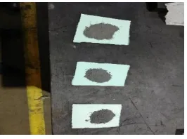
[image:3.612.73.206.202.301.2]The solution was placed on a heater at 150°C for 2 hours and was also subjected to continuous stirring by using a magnetic stirrer to obtain a uniform mixture. The powder formed was then cooled back to room temperature and weighed according to the requirements for press forming.
Figure 1: NiO/YSZ Cermet
4.2PRESS FORMING
In press forming, a pair of tools called a “die” is mounted inside a press and then a material (such as metal) is placed inside the die. The press then applies high pressure (3000 tons of force or higher on large presses) and the material is formed to match the shape of the die. In other words, press forming is a forming technology where a pressing force is applied to a material to deform it (by bending, stretching, etc.) to match the size and shape of the die, and the material then maintains that shape forever.
4.3 COATING OF YSZ ELECTROLYTE ON THE ANODE
Yttria stabilized zirconia is mainly used for the electrolyte due to its ability to conduct oxide ions and also in the anode as the electrolyte component along with an electronic conductor to induce mixed ionic electronic conduction (MIEC) properties. YSZ is a ceramic material, and its oxide ion conducting properties are prominent in a temperature range of 600o C to 1000°C. It is important to note that hafnium (Hf) may be present as an impurity of zirconia (ZrO2) in minute quantities due to difficulties in separation; however, it does not pose any problems as Hf is capable of conducting ions.
A certain quantity of 8YSZ was mixed with Iso-Propyl alcohol by using ultrasonic stirring process. The mixture was then coated on to the surface of the anode by using spray coating process. Nitrogen was used as the carrier gas in the gun to increase the velocity of the fluid coming out from the nozzle and to separate the mixture into fine droplets. The coating was then dried at 200°C for 30 minutes.
4.4 COATING OF LANTHANUM STRONTIUM MANGANITE ON ELECTROLYTE
LSM is commonly used as a cathode material
in commercially produced solid oxide fuel
cells (SOFCs) because it has a high electrical conductivity at higher temperatures, and its thermal expansion coefficient is well matched with yttria-stabilized zirconia (YSZ), a common material for SOFC electrolytes.
A similar method of coating was adopted to coat LSM. A known quantity of LSM was stirred along with IPA and was coated to a diameter of 14.5mm by spray coating method. Care was taken to ensure that the anode and cathode do not come into contact as it may affect the fuel cell performance.
Sintering was carried out at 1400°C for 12 hours to reform the pellet to achieve the required levels of strength and hardness. It had been experimentally found that LSM/YSZ composites sintered at 1400°C for 12 hours formed an insulating lanthanum zirconated layer (La2Zr2O7) which was
detrimental to the SOFC performance.
4.5 CURRENT COLLECTORS
© 2019, IRJET | Impact Factor value: 7.211 | ISO 9001:2008 Certified Journal | Page 6913 Silver wires are fixed on both sides along the
circumference of the individual meshes. Silver paint is used to bring the mesh and wire into contact. After pre-heating the sample in an air oven at 200°C for over 1 hour, it is then subjected to firing at 750°C for 2 hours to adhere the sample to the wire.
Figure 2: Silver wire as current collector
4.6 SEALING OF CERAMIC TUBE WITH THE PELLET
The ceramic tube was sealed with the pellet by using a glass sealant. The powdered sealant was converted into a paste by using a chemical solvent. The paste was applied on to the circumference of the tube and pellet and also on the outer diameter of the tube. After application, the setup was exposed to an infrared atmosphere to facilitate initial setting. Once it was sufficiently dried the setup was placed in a muffle furnace at 700°C for 4 hours for sintering. This process ensured that the sealant was completely dry and achieved a compact, non-porous form.
5. RESULTS AND DISCUUSIONS
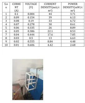
After sealing the ceramic tube with the pellet, the setup was tested at a temperature of 800°C with continuous supply of hydrogen without admitting oxygen.
An open circuit voltage (OCV) of 0.66V was noted at 800°C.By varying the load current in steps of 0.01A, the corresponding voltage was noted.
[image:4.612.311.584.136.467.2]
Table 1: Obtained Current, Voltage, Current Density,
Power Density
Figure 3: SOFC exposed to 600o C
Figure 4: Load
S.n
o CURRENT (A)
VOLTAGE
(V) DENSITY(mA/cCURRENT m2)
POWER DENSITY(mW/c
m2)
1 0.1 0.084 44 3.71
2 0.09 0.154 39 6.13
3 0.08 0.19 33 6.72
4 0.07 0.278 30 8.61
5 0.06 0.335 26 8.89
6 0.05 0.386 22.1 8.53
7 0.04 0.444 17.6 7.85
8 0.03 0.5 13 6.63
9 0.02 0.555 8.84 4.48
© 2019, IRJET | Impact Factor value: 7.211 | ISO 9001:2008 Certified Journal | Page 6914
Chart 1: Current Density v Voltage
A plot was drawn between voltage and current density. The highest current density of 44
mA/cm² was recorded against a voltage of 0.084V.
Chart 2 : Voltage v Current
A plot of voltage and current was drawn with voltage on y axis and current on x axis. Peak voltage of 0.606V was noted for a current of 0.01A. A decrease in voltage was noted as current was increased due to resistive losses.
Chart 3: Power Density v Current Density
From the power density vs current density graph it can be inferred that power density increases until current density reaches 33 mA/cm² after which there is a decrease in power density due to resistive losses.
6.CONCLUSION
By means of this project we have successfully developed an anode supported SOFC which has NiO/YSZ as anode and LSM as Cathode. Under the operating temperature of 800o C with hydrogen as fuel, an open circuit voltage of 0.66 V was recorded. The 2 mm thick pellet gave a maximum powder density of 8.89 mW/cm2 under the above mentioned conditions. By the applications of modern technology, the thickness of the pellet can be reduced to micron meters. These thin pellets will have vey less resistance and high levels of ionic conductivity, thereby increasing the output power
ACKNOWLEDGEMENT
We like to extend our gratitude to Dr. Mani Narayanaswamy M.Phil., Ph.D and Dr. Aristatil Ganesan M.Tech., Ph.D. Of Aatral Innovations Pvt. Ltd., chennai for their guidance.
© 2019, IRJET | Impact Factor value: 7.211 | ISO 9001:2008 Certified Journal | Page 6915
REFERENCES
[1] Weaver, G. (2002). World Fuel Cells - An Industry Profile with Market Prospects to 2010, 1st ed., Elsevier, New York, pp. 234.
[2] Barbir, F. (2005). PEM Fuel Cell. 2005, Elsevier Inc, UK:
[3] Brett, D. and Brandon, N., Bipolar Plates: The Lungs of The PEM Fuel Cell. The Fuel Cell Review, Vol. 2, No. 1, 2005, pp. 15-23.
[4] Fuel cell book by Majumdar Pradip. © 2014 by Taylor & Francis Group, LLC CRC Press is an imprint of Taylor & Francis Group, an Informa business.
[5] SC Shingal, Elsevier, Solid State Ions, 2000, 305(2000) 315.
[6] Kazempoor P, Dorer V, Weber A. Modelling and evaluation of building integrated SOFC systems. Int J Hydrogen Energy 2011;36:13241e9.
[7]
https://www.sciencedirect.com/topics/chemistry/s olid-oxide-fuel-cells