© 2019, IRJET | Impact Factor value: 7.211 | ISO 9001:2008 Certified Journal | Page 8112
Computer Aided Design and Finite Element Analysis of
Swing Jaw
Plate of Jaw Crusher
Manas Samal
1*, Tapan kumar Bugudei
21,2
Asst. Professor, Department of Mechanical Engineering, CUTM, Rayagada, India
---***---Abstract -
Jaw crusher is a machine designed to reducelarge solid particles of raw material into smaller particles. Crushers are major size reduction equipment used in mechanical, metallurgical and allied industries. Based on the mechanism used crushers are of three types namely Cone crusher, Jaw crusher and Impact crusher. Traditionally, stiffness of swing plates has not been varied with changes in rock strength. Rock strength has only been of interest because of the need to know the maximum force exerted by the toggle for energy considerations. Design of lighter weight jaw crushers will require a more precise accounting of the stresses and deflections in the crushing plates than is available with traditional techniques. Efforts to decrease energy consumed in crushing have lead to consideration of decreasing the weight of the swing plate of jaw crushers for easily crushed material. In the present work the design of the swing jaw plate using point-load deformation failure (PDF) relationships along with interactive failure of rock particles as a model for such a weight reduction. The design of the corrugated swing jaw plate is carried out by using CAD i.e. jaw crusher plate has been solid modeled by using CatiaV5R15. The calculated dimensions are validated with the drawing of reputed manufacturers. Finite Element Analysis of jaw plates are carried out by using ALGOR V19 software. Computerization of the theoretical design calculations of jaw plates of the jaw crusher has been carried out. The computerized program facilitates for quick design of the plates of the jaw crusher. The different comparisons of corrugated swing jaw plates behavior, calculated with the traditional and the new FEA failure models with stiffeners, shows that some 10-25% savings in plate weight may be possible.
Key Words: Jaw Crusher; Computer Aided Design (CAD);
Finite Element Analysis; Solid Modelling; Corrugated Jaw plate; Stiffened-Jaw Plate..
1. INTRODUCTION
Jaw Crushers are used to reduce the size of many different types of materials in many applications. The Jaw Crusher was first introduced by Eli Whitney Blake in 1858 as a double-toggle Jaw Crusher. Introduced in 1906, McLanahan’s Universal Jaw Crusher was one of the first modern era overhead eccentric Jaw Crushers. On the overhead eccentric style Jaw Crusher, the moving swing jaw is suspended on the eccentric shaft with heavy-duty double roll spherical roller bearings. The swing jaw undergoes two types of motion: one
is a swing motion toward the opposite chamber side (called a stationary jaw die due to the action of a toggle plate), and the second is a vertical movement due to the rotation of the eccentric. These combined motions compress and push the material through the crushing chamber at a predetermined size.
They are available in various sizes and capacities ranging from 0.2 ton/hr to 50 ton/hr. They are classified based on different factors like product size and mechanism used. Based on the mechanism used crushers are of three types namely Cone crusher, Jaw crusher and Impact crusher. The first stage of size reduction of hard and large lumps of run-of-mine (ROM) ore is to crush and reduce their size. Large scale crushing operations are generally performed by mechanically operated equipment like jaw crushers, gyratory crusher and roll crushers. For very large ore pieces that are too big for receiving hoppers of mechanically driven crushers, percussion rock breakers or similar tools are used to break them down to size. The mechanism of crushing is either by applying impact force, pressure or a combination of both. The jaw crusher is primarily a compression crusher while the others operate primarily by the application of impact. Crushing is the process of reducing the size of the lump of ore or over size rock into definite smaller sizes. The crusher crushes the feed by some moving units against a stationary unit or against another moving unit by the applied pressure, impact, and shearing or combine action on them. The strain in the feed material due to sufficiently applied pressure, impact forces, or shearing effect when exceeds the elastic limit of the feed material, the fracturing will occur on them. The crushers are very much rugged, massive and heavy in design and contact surfaces have replaceable high tensile manganese or other alloy steel sheet having either flat or corrugated surfaces. To guard against shock and over load the crushers are provided with shearing pins or nest in heavy coiled springs. Many engineering structures consist of stiffened thin plate elements to improve the strength/weight ratio. The stiffened plates subjected to impact or shock loads are of considerable importance to mechanical and structural engineers. The main object of the present work is to propose an efficient use of modeling in the connection between the plate and the stiffener, and as part of it the constraint torsion effect in the stiffener. [1, 2 3 & 8]
© 2019, IRJET | Impact Factor value: 7.211 | ISO 9001:2008 Certified Journal | Page 8113
2) Analysis of data for identification of constraints3) Application of various methodologies such as Also further study of swing jaw plate with stiffener is done using finite element analysis.
4) The design and modeling jaw plates of crusher is accomplished by using CAD i.e. parametric design package (CATIAP3V5R15).
5) Comparison of the results obtained through Finite Element Analysis of jaw plates by using ALGOR V19 programming (Trail Version).
6) Result and Discussion which is extended to improve the strength/weight ratio of swing jaw plate by adding different number of stiffener elements on the jaw plates
1.1 Jaw Crushers: An Overview
Crusher is a machine designed to reduce large rocks into smaller rocks, gravel, or rock dust. Crushers may be used to reduce the size, or change the form, of waste materials so they can be more easily disposed of or recycled, or to reduce the size of a solid mix of raw materials (as in rock ore), so that pieces of different composition can be differentiated. Crushing is the process of transferring a force amplified by mechanical advantage through a material made of molecules that bond together more strongly, and resist deformation more, than those in the material being crushed do. Crushing devices hold material between two parallel or tangent solid surfaces, and apply sufficient force to bring the surfaces together to generate enough energy within the material being crushed so that its molecules separate from (fracturing), or change alignment in relation to (deformation), each other. The earliest crushers were hand-held stones, where the weight of the stone provided a boost to muscle power, used against a stone anvil. Querns and mortars are types of these crushing devices.[1,2,9,&12].
The first stage of size reduction of hard and large lumps of run-of-mine (ROM) ore is to crush and reduce their size. Softer ores, like placer deposits of tin, gold, mineral sands etc. do not require such treatment. Large scale crushing operations are generally performed by mechanically operated equipment like jaw crushers, gyratory crusher and roll crushers. For very large ore pieces that are too big for receiving hoppers of mechanically driven crushers, percussion rock breakers or similar tools are used to break them down to size. The mechanism of crushing is either by applying impact force, pressure or a combination of both. The jaw crusher is primarily a compression crusher while the others operate primarily by the application of impact. [1,2 & 8]
Jaw crusher is one of the main types of primary crushers in a mine or ore processing plant. The size of a jaw crusher is designated by the rectangular or square opening at the top of the jaws (feed opening). For instance, a 24 x 36 jaw crusher has a opening of 24" by 36", a 56 x 56 jaw crusher has a opening of 56" square. Primary jaw crushers are typically of
the square opening design, and secondary jaw crushers are of the rectangular opening design. However, there are many exceptions to this general rule. Jaw crusher is a primary type of crusher which has two jaws, out of which one is stationary attached rigidly with the crusher frame whereas the other moves between a small throw forward and retarded back successively to crush the ore or rock boulders.Jaw crushers are typically used as primary crushers, or the first step in the process of reducing rock. They typically crush using compression. The rock is dropped between two rigid pieces of metal, one of which then move inwards towards the rock, and the rock is crushed because it has a lower breaking point than the opposing metal piece. Jaw crusher movement is obtained by using a pivot point located at one end of the “swing jaw”, and an eccentric motion located at the opposite end. [1,2 & 7].
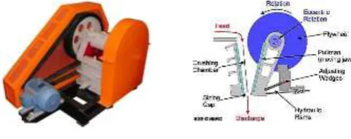
Fig -1: Schematic of Jaw Crusher
1.2 Working Principle of Jaw Crusher:
The working principal of Jaw Crusher is based on modern design "Cruching without Rubbing" The machine consists, two Jaws, one fixed and the other moving. The opening between them is smaller at the bottom and wider at the top. The pitman moving on an eccentric shaft on bearing, swing lever (Moving Jaw) swing on center pin. The Rock held in between two Jaws and crushed by mechanical pressure. The motor drives the belt pulley and the belt pulley drives the eccentric shaft to rotate, and make the moving jaw approach and leave the fixed jaw periodically, to crush, rub and grind the materials repeatedly, thus to make the material slower and slower and gradually fall down and finally discharge from the discharge opening. A fixed jaw mounted in a “V” alignment is the stationary breaking surface while the movable jaw exerts force on the rock by forcing it against the stationary plate. The space at the bottom of the “V” aligned jaw plates is the crusher product size gap or size of the crushed product from the jaw crusher. The remains until it is small enough to pass through the gap at the bottom of the jaws.[2,5,6 &7]
[image:2.595.308.558.289.388.2]© 2019, IRJET | Impact Factor value: 7.211 | ISO 9001:2008 Certified Journal | Page 8114
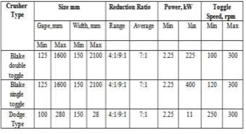
than the bottom opening or set pass through as product. Thefunction of the toggle(s) is to move the pivoted jaw. The retrieving action of the jaw from its furthest end of travel is by springs for small crushers or by a pitman for larger crushers. For a smooth reciprocating action of the moving jaws, heavy flywheels are used in both types of crushers and the performance of jaw crusher are shown in the table-1.
[image:3.595.56.268.206.362.2]Fig -1: Jaw Crusher Working Principle
Table- 1: Jaw Crusher Performances
1.3 Literature Survey
Ashish Kumar Shrivastava and Avadesh k. Sharma, (2012) “had review of a work carried out by researchers in the field of kinematic & dynamic analysis of the jaw crusher attachment. Kinematic & Dynamic analysis is helpful for understanding and improving the design quality of jaw crusher”. Ramkrushna S. More and Sunil J.Rajpal,(2013) “had analysis the crushers are major size reduction equipment used in mechanical , metallurgical and allied industries and focuses on review of a work carried out by researchers on analysis of swing jaw plate i.e. kinematic & dynamic analysis of the jaw crusher”. Bogonko Benson Omwenga et al., (2014) “had of previously analyzed kinematics and torque transmission characteristics of the horizontal Pittman stone crusher”. Shyam Sundar.V,(2014) “suggested that the practical kinematic characteristic of the
[image:3.595.38.290.422.559.2]© 2019, IRJET | Impact Factor value: 7.211 | ISO 9001:2008 Certified Journal | Page 8115
2. Computational Analysis
2.1
Solid Modeling of Swing Jaw Plates:Engineering components can be of various forms (sizes and shapes) in three- dimensions. A Solid can be thought of as composed of a simple closed connected surface that encloses a finite volume. The closed surface may be conceived as an interweaved arrangement of constituent surface patches, which in turn, can be individually considered as composed of a group of curves. Engineers have converged to numerous standard ways of perceiving a three-dimensional component by way of engineering drawings depicted on a two-dimensional plane (conventionally blue prints, but for CAD’s purpose, a display screen). Manufacturing and Rapid Prototyping (RP) both require computationally efficient and robust solid modelers. Other usage of solid modelers is in Finite Element Analyses (as pre- and post- processing), mass property calculations, computer aided process planning (CAPP), interference analysis for robotics and automation, tool path generation for NC machine tools, shading and rendering for realism and many others. Developing a CAD software is an arduous and challenging task. However, CAD/CAM had penetrated virtually every industry including Aerospace, Automotive, Construction, Consumer products, Textiles and others. Software has been developed over the past two decades for interactive drawing and drafting, analysis, visualization and animation. A few widely used products in Computer Aided Design and drafting are Pro-Engineer, AutoCAD, CATIA, IDEAS, and in analysis are NASTRAN, ABAQUS, ANSYS and ALGOR. Many of these softwares are being planned to be upgraded for potential integration of design, analysis, optimization and manufacture.[2,10,11 & 12]
Fig- 2: Sketch of Swing Jaw Plates Base Feature
Fig-3: Solid Model of Corrugated Swing Jaw Plate
2.2 Finite Element Method Applied To Swing Jaw
Plate
There are three basic approaches to FEA: the h, p and h-p methods. With the h method, the element order (p) is kept constant, but the mesh is refined infinitely by making the element size (h) smaller. With the p method, the element size (h) is kept constant and the element order (p) is increased. With the h-p method, the h is made smaller as the p is increased to create higher order h elements. Either reducing the element size or increasing the element order will reduce the error in the FEA approximation. FEA software exists for all three methods. Before examining which may be superior, one must first determine which element type results in greater model, and therefore analysis, accuracy. The objective of finite element analysis of real world models is to simulate destructive testing using a minimum amount of computer memory, computation time and modeling time. The concept of FEA is simple and well-understood. The design is turned into a mesh of finite elements. FEA then tests each finite element for how it responds to such phenomena as stress, heat, fluid flow or electrostatics. FEA has been key in transferring design and analysis from drafting boards. A designer can select from a variety of element types when building an FEA model. The principal issue n selecting a finite element type is accuracy. Until recently, the engineer would build the solid mesh manually, attempting to make an accurate representation of the part design. [2,10,11 & 12]
2.3 Swing Jaw Plates Static Stress Analysis Using
ALGOR
© 2019, IRJET | Impact Factor value: 7.211 | ISO 9001:2008 Certified Journal | Page 8116
Fig- 4: Swing Jaw Plate Model Ready for Static StressAnalysis
Fig-5: Swing Jaw Plate Model Ready for Meshing (Discretization)
Fig-6: Showing Swing Jaw Plate Model Meshing Results
Fig-7: Swing Jaw Plate Model Ready for Selection of Element Type
Fig-8: Showing Swing Jaw Plate Model Boundary Condition (Support)
Fig-9: Showing Swing Jaw Plate Model Boundary Condition (Toggle Force)
Fig-10:Showing Swing Jaw Plate Model Applying Point Loads
Linear Static Stress Analysis:
© 2019, IRJET | Impact Factor value: 7.211 | ISO 9001:2008 Certified Journal | Page 8117
Fig-12: Showing Swing Jaw Plate DisplacementFig-13: Showing Swing Jaw Plate Allowable Stress Value
Fig-14: Showing Swing Jaw Plate Factor of Safety Tool
Fig-15: Showing Swing Jaw Plate Factor of Safety Values
3. Results and Discussion
Static Stress Analysis Results:Since the PDF data were most complete for the amphibolites, these load-deformation relations were employed in the model. Laboratory data were extrapolated for the larger sizes according to the dotted line in the strength-deformation size relationships in Figs. 3.7 and 3.9. To obtain a comparison for the interactive model, the same beam model (same EI) was loaded with the same sized particles which were all assumed to fail simultaneously. The stepwise pressure distribution was found by distributing the ultimate point load for that size particle over the distance midway between each of the two adjacent loads. The similarity of the two distributions further substantiates the size-strength relations and particle size distribution employed in this study. The numerical and FEA models using ALGOR are employed to calculate maximum tensile stresses and maximum toggle forces (T) for a variety of model plate thicknesses, using the rock properties of the amphibolites. The comparisons are presented in Table 2.
Table- 2: Effect of thickness on maximum response when
loaded with amphibolites
Fig-16: Maximum Tensile Stress Response for Various Jaw Plate
Thicknesses
4. CONCLUSION
© 2019, IRJET | Impact Factor value: 7.211 | ISO 9001:2008 Certified Journal | Page 8118
the present formulation is demonstrated by comparing theresults with theoretical analysis solution. Moreover, the results of stresses are calculated at points and they are expected to differ from the analytical solutions. The present jaw plate models accurately predict the various stresses for plates. As the present models are developed using a non-conforming element, the results can be further improved using a conforming element with improved mesh size thereby increased no of elements. Infact, FEM results approach the true solutions, with the increase in the number of elements. In case stiffened jaw plates as the number of stiffener increases the strength/weight ratio of the jaw plate increases making it stronger than that of without stiffener. The stiffened plate models which leads to 15% saving in energy, of course this 15% is an estimate. Consideration of the two particles between the crusher plates reveals the importance of the point-load failure mechanism. Thus, any design based upon both deformation and strength must begin with a point-load idealization. Design of lighter weight jaw crushers will require a more precise accounting of the stresses and deflections in the crushing plates than is available with traditional techniques. Rock strength has only been of interest because of the need to know the maximum force exerted by the toggle for energy considerations. Design of crushers for specific rock types must consider the variability of point load strength and deformability implicit in any rock type name and quarry sized sampling region.
REFERENCES
[1] Gupta Ashok, Yan D.S. “Mineral Processing Design and
Operation-An introduction”, Published by Elsevier, 2006, Pages 99-127.
[2] Bharule Ajay Suresh, “M. Tech Thesis Computer Aided
Design and Analysis of Swing Jaw Plate of Jaw Crusher”, NIT Rourkela, June 2009
[3] Ashish Kumar Shrivastava and Avadesh k. Sharma, “A
Review On Study Of Jaw Crusher”, International Journal of Modern Engineering Research (IJMER), Vol.2, Issue.3, May-June 2012 pp-885-888 ISSN: 2249-6645.
[4] Ramkrushna S. More and Sunil J.Rajpal, “A Review on
Study of Jaw Plates of Jaw Crusher”, International Journal of Modern Engineering Research (IJMER), Vol.3, Issue.1, Jan-Feb. 2013 pp-518-522 ISSN: 2249-6645.
[5] Bogonko Benson Omwenga et al., “Kinematic And Static
Force Transmission Analysis Of A Single Toggle Jaw Crusher”, University of Nairobi, MFO 02/2014.
[6] Shyam Sundar.V, “ Optimum Design And Analysis Of
Single Toggle Jaw Crusher”, International Journal of Advance Research In Science And Engineering ,IJARSE, Vol. No.3, Issue No.12, December 2014 ISSN-2319-8354(E) 194
[7] Ramkrushna S. More, “A Design & Analysis of Swing Jaw
Plates of Jaw Crusher”, International Journal of Enhanced Research in Science Technology & Engineering, ISSN: 2319-7463, Vol. 3 Issue 4, April-2014, pp: (400-408), Impact
[8] M.avulaiah and T.seshaiah, “Computer Aided Design and
Analysis of Swing Jaw Plate of Jaw Crusher”, @ 2015
IJSETR, ISSN 2319-8885, Vol.04,Issue.09, April-2015, Pages:1611-1616.
[9] R. R. Patil and P.S.Desale, “Experimental Effect On Jaw
Crusher Plate”, Vol-1 Issue-5 2015 IJARIIE-ISSN(O)-2395-4396.
[10] Virendrasinh N Dodiya, Prof. Vijay Pipalia and Prof.
Dhaval P Patel, “Investigation of Effect of Without Stiffener on Swing Jaw Crusher Plate by Finite Element Analysis” IJSRD - nternational Journal for Scientific Research & Development| Vol. 3, Issue 01, 2015, ISSN (online): 2321-0613
[11] S. D. Pandey, V. K. Nema and S. K. Shukla, “ Theoretical
Analysis of Swing Jaw Plates used in Heat Exchanger”, International Journal of Energy Engineering 2016, 6(1A): 23-31.
[12] Malavatu Suneel Kumar and .Ch.Sreedhar, “Computer
Aided Design And Analysis Of Swing Jaw Plate Of Jaw”, Anveshana’s International Journal Of Research In Engineering And Applied Sciences, VOLUME 1, ISSUE 11 (2016, NOV).
BIOGRAPHIES
Mr. Manas Samal, received his Bachelor Degree in Mechanical Engineering in 2016 from CUTM, Paralakhemundi, Odisha, India and in 2019 received his M.Tech degree in Mechanical Engineering from GIET (Autonomous), Gunpur, Rayagada, India. He is currently working as Asst. Professor under the Department of Mechanical Engineering at Centurion University, Rayagada, India. His area of interest includes Machine Design, Composite Materials, and Production and operation management. He has presented and published many papers in National & International conferences and journals.