© 2019, IRJET | Impact Factor value: 7.211 | ISO 9001:2008 Certified Journal | Page 7055
EFFECT OF RELATIVE STIFFNESS OF BEAM-COLUMN JOINT ON
INTERNAL FORCES IN REINFORCED CEMENT CONCRETE STRUCTURES
Mr. Prashantkumar. Pratap. Datanal
[1], Prof. Dr. Vinod Hosur
[2]1
M.Tech student, Dept. of Civil Engineering, KLS Gogte Institute of Technology, Belagavi, Karnataka, India
2Professor, Dept of Civil Engineering, KLS Gogte Institute of Technology, Belagavi, Karnataka, India
---***---Abstract - For the beam design, the joints between beam and column is traditionally considered a rigid connection which actually not fully rigid and therefore accounted an extra moment leading to structural over-design and subsequently higher cost of beam construction. In this project the study is carried out for the effect of relative stiffness of beam column on internal forces in reinforced cement concrete structures. The structure geometry was 4m X 5m and G+2 building was analyzed using STAAD.Pro Software. The frame of 4m with 3 bays was considered for the study. Increased in the grade of concrete, the relative stiffness of the beam column joint varies. The effect of grade of concrete and steel on the flexural strength of beam and on the compressive strength of column was studied. The comparison of the bending moments for different grade of concrete and by the methods of moment of inertia was studied.
Key Words - RCC Beam-column joint, Relative Stiffness, Partially restrained connection, modular ratio, STAAD.PRO Software.
1. INTRODCUTION
In reinforced concrete frame structures, the beam-column joint is a very critical area where elements meet in all the three directions and this area should be of particular concern in buildings. Building joints ensure structural continuity and transmit forces present at the ends of the components. Beam-column connections must effectively transmit shear forces, bending moments and other related structural response parameters and must maintain structural integrity. In reinforced concrete structures, beam failure often occurs at the beam-column joints, making the node one of the most critical parts of the structure. Beam-column joints play an important role in the lateral stability of the structure.
During analysis and in the design of beam, the beam column joint is considered as fixed, but in reality the joint is not fully rigid, it is semi rigid. In the rigid joint, the joint does not allow any rotations between the connected members while in the pinned joints, the connected members joint are characterized by the free rotational movement and prevents the transmission of the bending moments. In the real beam-column connections are represent partially restrained behavior, wherein the relative flexural stiffness of beam and column joint at the connection affect the beam-column
moment-rotation relationship. Because of the semi-rigid behavior, beam-column connections can affect the moment redistribution along reinforced concrete structures.
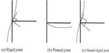
a) Rigid joint: Rigid joints prevent the relative rotation of members so that they have capability to transfer the bending moments. Rigid joints are expressed by fixed supports where the relative rotation is prevented. In Reinforced concrete structure, rigid joints are made by overlapping of steel reinforcement into members.
b) Semi rigid joint: Semi rigid joints allow the relative rotation of members but up to a specific angle, this angle depends on both the stiffness of the joints and the moment subjected to the joint. In reinforced concrete structures, semi rigid are formed when, steel reinforcement are not overlapping between members but members are poured altogether.
[image:1.595.326.514.491.582.2]c) Pinned joint: Pinned joints allow the members to rotate about them and they don’t transfer any moments. In reinforced concrete structures, they must be true hinges that means to be pins that members rotate about them.
Figure 1: Different joints according to the rotational stiffness
1.1 Calculation of moment of inertia by two
different methods
i) Gross area method: In this method, moments of inertia of the whole cross section without considering the moment of inertia of steel.
ii) Equivalent area method: In this method, moments of inertia of the whole cross section with considering the moment of inertia of steel.
© 2019, IRJET | Impact Factor value: 7.211 | ISO 9001:2008 Certified Journal | Page 7056
Here the modulus of elasticity of concrete is calculated usingcharacteristic of strength of concrete in N/mm2 as per IS-456
code. The table indicated the modulus of elasticity of concrete for different grade of concrete.
Modulus of elasticity of concrete= Ec = 5000 X √fck. Where fck = Characteristics of strength of concrete in N/mm2.
Table1: Modulus of elasticity of concrete for different grade of concrete.
Grade of concrete Modulus of elasticity (Ec) in N/mm2
M20 22360.68
M25 25000
M30 27386.128
b) Modular ratio (m):
Modular ratio (m) is the defined as the ratio of modulus of elasticity of steel to the modulus of elasticity of concrete. The table indicated the modular ratio for different grade of concrete.
Modular ratio (m) = Modulus of elasticity of steel / Modulus of elasticity of concrete.
Take Modulus of elasticity of steel = 2X10⁵ N/mm2.
Table2: Modular ratio for different grade of concrete.
Grade of concrete Modular ratio (m)
M20 8.994
M25 8
M30 7.303
After calculating the modular ratio for grade of concrete, the product modular ratio and area of steel for column is computed as shown in table. As the grade of concrete increases the product of modular ratio and area of steel decreases.
Take area of steel (Ast) for column = 4#12+4#16 = 1256.65 mm2.
Table3: Product of modular ratio and area of steel for different grade of concrete.
Grade of concrete Modular ratio (m) X area of steel (Ast)
M20 11239.765
M25 10053.12
M30 9177.24
c) Calculation of the sectional properties for column section for M20 grade of concrete
i) Calculation of moment of inertia in z-z axis by gross area method
Iz = b X d3 /12
Iz = 230 X 3803/12
Iz = 1052 X 106 mm4.
ii) Calculation of moment of inertia in z-z axis by equivalent area method
Iz = (b X d3/12) + (m X Ast) X ȳ2.
Iz = (230 X 3803/12) + ((113.1 X 4 X 8.9443 X 1502) + (201.1
X 4 X 8.9443 X 1252))
Iz = 1052 X 106 + 203.46 X 10⁶
Iz = 1255.5 X 106 mm4
.
d) Calculation of sectional properties of beam section for M20 grade of concrete
i) Calculation of moment of inertia in z-z axis by gross area method
Iz = b X d3 /12
Iz = 230 X 4603/12
Iz = 1865.61 X 106 mm4.
ii) Calculation of moment of inertia in z-z axis by equivalent area method
Iz = (b X d3/12) + (m X Ast) X ȳ2.
A = (230 X 460) + 427.3 A = 106227.3mm2
ȳ= 230.8 mm.
Iz = (b X d3/12) + (m X Ast) X ȳ2.
Iz = (230 X 4603/12) + ((427.3 X 8.944) X 230.82)
Iz = 1865.61X 106 + 203.61X 10⁶
© 2019, IRJET | Impact Factor value: 7.211 | ISO 9001:2008 Certified Journal | Page 7057
e) Comparison of gross area method and equivalent areamethod
Table4: Comparison of gross area method and equivalent area method.
Section Moment of inertia (Izz) in mm4 by
Gross area method Moment of inertia (Izz) in mm4 by
Equivale nt area method Variation in percentage Column (230mm X 380mm) 1052 X 106 1255.5 X 106 19.34% Beam (230mm X 460mm) 1865.61 X 106
2069.22 X 106
10.91%
1.2 Objectives of the present study
1. To study the effect of relative stiffness of beam column joint in the reinforced cement concrete structures.
2. To study the effect of grade of concrete and steel on the flexural and compressive strength
2. Literature review
Wahid Ferdous (2014): He considers the partial rigid joint between beam and column. The stiffness of the joint is the function of the bending moment and deflection of the beam. The analytical model was developed for the bending moment and deflection considering a moving point load on the beam. He considers the joint stiffness namely ka and kb at the supports and uses the corresponding bending moments at the two supports to calculate the slope of the support by the definition of stiffness. The tangent of slope is also calculated. Using moment area theorem, the general equations for the bending moment at the both supports was computed which mainly depends on the stiffness of the joint, beam stiffness and the position of the load. He also computed the position of the maximum deflection equation; this equation includes deflection of the beam due to the simply supported action and also the semi rigid action. The theoretical model is applied for different support conditions namely rigid support, simply support and propped cantilever. He tabulated the end moments, location of maximum deflection and magnitude of the maximum deflection using the boundary condition. He
compares the theoretical model results with the traditional equation, the values of the bending moment and deflection are found out to be similar. Hence he concluded that, the theoretical model for moment and deflection can explain the intermediate behavior of pinned and rigid joint condition and can easily introduce in everyday design practice. The semi rigid joint between beam and column provides a lower moment at the end of the beam when it is compared with fully rigid joint.
G. M. S. Alva et al., (2009) presents the comparison experimental data with analytical model for the beam-column connection. The experimental data for the moment-rotation curve of monolithically beam- column connections. Experimental was carried out by Alva with five physical models of exterior beam column connections, without slabs, beams with cross sections of 20X40 cm and columns with cross sections of 20X30 cm. Initially, the experimental data are analyzed in order to determine the influence of the compressive strength of concrete and the transverse reinforcement available in the beam-column joint region. The experimental results are compared with the analytical model proposed by Ferreira for the determination of the moment-rotation curve for the semi rigid connection. According to the Ferreira, the relative rotation between the cross section of the beam and column is a result of two mechanisms of deformation i) elongation of beam tensile reinforcement correspondent to the anchorage length in the column. ii) Bending deformation of the beam end in the region of discontinuity. Ferreira presents a general expression for the determination of the moment- rotation curve in beam-column connections until the yielding moment taking into account above mentioned both deformation mechanisms. The experimental results were compared with the theoretical model and plotted the graph between the relative rotation (rad) and moment (kN-m) for all the five models. They concluded that, the theoretical response of the analytical model could be improved by including the deformation mechanism.
3. Effect of relative stiffness on beam column joint
a) Structure Geometry
© 2019, IRJET | Impact Factor value: 7.211 | ISO 9001:2008 Certified Journal | Page 7058
Figure 2: Floor plan and Typical section of buildingLoads as per IS 875 (part 1 and part2) Total dead load on slab = 5.75kN/m2
Wall load = 12kN/m Live load = 2kN/m2
[image:4.595.341.547.149.307.2]Load combinations: 1) Dead load + Live load 2) 1.5(Dead load + Live load)
Figure 3: Loading diagram of frame
b) Effect of grade of concrete on relative stiffness of beam column joint
After Analysis of the structure, the design of the outer and inner frame is carried out for constant grade of steel (Fe415N/mm2) and different grade of concrete (M20, M25,
M30) with area of steel in column is kept constant. After designing, the column and beam sections of frame in mm are obtained are shown below for different grade of concrete (M20, M25, M30). As the grade of concrete is increased in column, the size of column reduces for constant
[image:4.595.322.550.381.642.2]grade of steel and area of steel in column. The relative stiffness varies. Hence the bending moment in the inner and outer frame varies.
Figure 4: Column and Beam sections of frame in mm
[image:4.595.55.277.439.623.2]© 2019, IRJET | Impact Factor value: 7.211 | ISO 9001:2008 Certified Journal | Page 7059
Figure 6: Moment of inertia for different grade of concrete [image:5.595.315.553.439.635.2]c) Effect of grade of concrete and steel on flexural strength of beam (Effect on depth and Area of steel for given flexural strength)
Table 5: Effect of grade of concrete and steel on flexural strength of beam
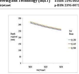
Graph 1: Variation of depth required for beam section for the variation in grade of concrete.
The graph indicates the effect of grade of concrete and steel on the depth required for the beam section. The horizontal axis indicates the grade of concrete and vertical axis indicates the depth required for the section. As the grade of concrete increased, the depth required for the beam section is reduces. As the grade of steel increased, the depth required for the beam section is increases.
Graph 2: Variation of area of steel required for beam section for the variation in grade of concrete.
© 2019, IRJET | Impact Factor value: 7.211 | ISO 9001:2008 Certified Journal | Page 7060
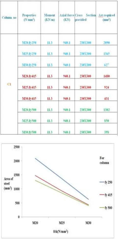
Table 6: Effect of grade of concrete and steel oncompressive strength of Column
Graph 3: Variation of area of steel required for column section for the variation in grade of concrete and steel.
The graph indicates the effect of grade of concrete and steel on area of steel required for the column section. The horizontal axis indicates the grade of concrete and vertical axis indicates the area of steel required for the column section. As the grade of concrete increased, the area of steel required for the column section is increases. As the grade of steel increased, the area of steel required for the column section is reduces.
3.1. Comparison of a bending moments for different
methods of calculating moment of inertia
[image:6.595.318.545.252.504.2]In this case the effect of methods calculating of moment of inertia on the bending moments is presented. For the constant cross section, the moment of inertia is calculated by gross area and equivalent area method (considering the area of steel). The moment of inertia increases in the equivalent area than the gross area method. Frame of 4m and loading condition is analyzed in the STAAD.Pro for the both methods for M20 grade of concrete and Fe 415N/mm2 steel.
Figure 7: Bending moments for different methods of calculating moment of inertia
4. Conclusions
1. As the grade of concrete increases the modulus of elasticity increases. Hence the modular ratio decreases. As the moment of inertia in the equivalent area method (considering area of steel) differs from the gross area method by 10-20%. The moment of inertia increases for the cross section by considering the equivalent area method of calculation of moment of inertia. It will affect the relative stiffness of the beam column joint and also internal forces.
© 2019, IRJET | Impact Factor value: 7.211 | ISO 9001:2008 Certified Journal | Page 7061
stiffness of members. As moment of inertia varies, therelative stiffness of that member varies. Hence the moment in the member is distributed to the ad joint member.
As the grade of concrete is increased in the column, the size of the column decreases, hence the moment of inertia reduces in the column. Therefore because of moment of inertia, the relative stiffness of the column decreases, hence the moment in the column is distributed to the ad joint beams by keeping the grade of steel and area of steel in the column constant. Due to the distribution of moments the column moment reduces, the end and mid span moment in the ad joint beam for inner and outer frame increases. The moment of inertia of column varies the deflection in the beam and sway of column occurs. As the grade of concrete is increased, the deflection of the beam and sway of column increases.
3) As the grade of concrete is increased in the beam, the depth required for the beam section decreases. Hence the area of steel required for the beam section increases. As the grade of steel is increased, the depth required for the beam section increases. Hence the area of steel required for the beam section decreases for the given flexural strength. As the grade of concrete increased for column, the area of steel required for the column section is increases. As the grade of steel increased, the area of steel required for the column section is reduces for the given axial forces.
4) Due to the variation in the moment of inertia by equivalent area method and gross area method, it will affect the relative stiffness of the beam column joint and internal forces. Hence the bending moments in the inner and outer frame varies from 1-3%. Moment in the inner and outer frame at the exterior support decreases in the equivalent area method than the gross area method, where as in the interior support increases. This variation because of the relative stiffness of beam column joint. Hence there is no larger variation in the bending moment we can safely use the gross area method for time saving.
5. References
[1]. Wahid Ferdous, “Effect of beam-column joint stiffness on the design of beams”, Engineering Structures, Vol. 2, pp. 701-70, Dec 2014.
[2]. G. M. S. Alva, M. A. Ferreira, A. L. H. C. EL Debs, “Partially Restrained Beam-Column Connections in Reinforced Concrete Structures”, IBRACON Structures and Materials Journal, Vol. 2, pp. 356-367, Dec 2009.
[3]. Amanat, K.H. and Enam, “study of the semi rigid properties of reinforced concrete beam-column joint”, journal of civil engineering the institution of engineering, vol.27, no.1, pp.10, 2015.