warwick.ac.uk/lib-publications
Manuscript version: Author’s Accepted Manuscript
The version presented in WRAP is the author’s accepted manuscript and may differ from the
published version or Version of Record.
Persistent WRAP URL:
http://wrap.warwick.ac.uk/130203
How to cite:
Please refer to published version for the most recent bibliographic citation information.
If a published version is known of, the repository item page linked to above, will contain
details on accessing it.
Copyright and reuse:
The Warwick Research Archive Portal (WRAP) makes this work by researchers of the
University of Warwick available open access under the following conditions.
Copyright © and all moral rights to the version of the paper presented here belong to the
individual author(s) and/or other copyright owners. To the extent reasonable and
practicable the material made available in WRAP has been checked for eligibility before
being made available.
Copies of full items can be used for personal research or study, educational, or not-for-profit
purposes without prior permission or charge. Provided that the authors, title and full
bibliographic details are credited, a hyperlink and/or URL is given for the original metadata
page and the content is not changed in any way.
Publisher’s statement:
Please refer to the repository item page, publisher’s statement section, for further
information.
Computing and Relaying : Utilizing Mobile Edge
Computing for P2P Communications
Min Qin, Li Chen, Nan Zhao,
Senior Member, IEEE,
Yunfei Chen,
Senior Member, IEEE,
F. Richard Yu,
Fellow, IEEE,
Guo Wei
Abstract—Besides increasing the computing capacity of edge devices, mobile edge computing (MEC) can also be utilized to help communication. This paper proposes an MEC-assisted computing and relaying scheme to enhance the throughput of uncompressed data for mobile peer-to-peer (P2P) communications. We assume that the target data has a dynamic compression rate during the transmission from one mobile device to another through a relay node with MEC. In order to obtain the optimal transmission and compression strategy for the mobile devices and the relay node, a cost function that defines the tradeoff between energy consumption and latency time is investigated first. Then a closed-form solution is derived by minimizing the cost function with respect to practical constraints. Compared with conventional P2P communications without MEC, the proposed model breaks the bottleneck of P2P communications by decoupling the data compression rates at the two sides of MEC server. Numerical results verify the effectiveness of the proposed scheme.
Index Terms—Computation offloading, computing and relay-ing, mobile edge computrelay-ing, P2P communication.
I. INTRODUCTION
With the fast growth of mobile devices and connections, monthly Internet traffic will reach 44 GB per capita by 2022, up from 13 GB per capita in 2017 [1]. This trend will generate a huge burden on the existing centralized network architecture, since all the resource-limited devices rely on the computation support from remote clouds. To solve this problem, decentralized mobile edge computing (MEC) has attracted great research interest [2–5]. It focuses on integrating the computing and communication resources at the edge of networks to consume the user data locally.
The MEC theory, first proposed by Cisco [6] and ETSI [7], has been applied in many scenarios, such as video stream analysis [8], intelligent video acceleration [9], computing
This work was supported by the National Key Research and Development Program of China (Grant No. 2018YFA0701603), National Natural Science Foundation of China (Grant No. 61601432), and USTC Research Funds of the Double First-Class Initiative. (Corresponding author: Li Chen)
M. Qin, L. Chen and G. Wei are with Department of Electronic Engineering and Information Science, University of Science and Technology of China. (e-mail: [email protected]{chenli87, wei}@ustc.edu.cn).
N. Zhao is with the School of Information Science and Technology, Qing-dao University of Science and Technology, QingQing-dao 266000, China, and also with the School of Information and Communication Engineering, Dalian Uni-versity of Technology, Dalian 116024, China (e-mail: [email protected]). Y. Chen is with the School of Engineering, University of Warwick, Coventry CV4 7AL, U.K. (e-mail: [email protected]).
F.R. Yu is with the Department of Systems and Computer Engi-neering, Carleton University, Ottawa, ON, K1S 5B6, Canada (email: [email protected]).
Copyright (c) 2015 IEEE. Personal use of this material is permitted. However, permission to use this material for any other purposes must be obtained from the IEEE by sending a request to [email protected].
assistance [10] and IoT gateway [11]. In these scenarios, the computing tasks of edge devices are offloaded to MEC servers or the data streams are adjusted by MEC servers to accelerate the transmission. For example, moving the video analysis away from the video camera reduces the equipment cost and saves the core network load of transporting large data video to re-mote clouds [8]. Also, intelligent video acceleration is realized by caching and processing multi-bit-rate video collaboratively in MEC servers [9]. Therefore, both computation offloading and communication acceleration are key research issues in MEC.
In the literature, computation offloading has been widely investigated, including the task partition strategy and the al-location of computing and communication resources. For task
partition, Wang et al.in [12] considered the minimization of
the energy consumption for the users with fixed tasks subject
to offloading delay constraints. Mao et al. in [13] adopted
both the execution delay and task failure as the performance metrics with dynamic voltage and frequency scaling (DVFS) [14] and energy harvesting techniques [15]. An offloading policy from a single user to multiple MEC servers with
multi-tasks was proposed by Dinhet al.in [16] by minimizing the
maximum execution delay. You et al. in [17] exploited the
CPU-state information of non-causal helpers, such as powerful laptops, to design energy-efficient computing policies via peer-to-peer (P2P) links for sharing computation resources at peer
mobiles. For resource allocation, Youet al.in [18] developed
an energy-efficient allocation policies for a multiuser MEC system, in which TDMA and OFDMA were considered. Computation offloading and resource allocation for indivisible tasks in wireless cellular networks with a single MEC server
were investigated by Wang et al. in [19, 20]. Tan et al. in
[21] proposed a virtual MEC framework that served multiple users with both edge computing and caching. In our previous work [22], we proposed a computation offloading model to maximize the processing capacity of power-constrained IoT devices with the assistance of an MEC server.
All the aforementioned research works focus on the compu-tation offloading strategy to enhance the computing capacity of edge devices via the communication links to MEC servers or
device helpers,i.e., use communication to boost computation.
However, there are very few research considering the use of computation to accelerate communication. In this paper, we will utilize MEC for the P2P communications among
edge devices,i.e., use computation to promote communication.
ap-plications. On the one hand, wireless communication as an essential component of mobile computing has quite low energy efficiency since the energy required for transmission of a single bit has been measured to be over 1000 times greater than that for a single 32-bit computation [23]. Therefore, this idea can significantly reduce the energy consumption in wireless communication systems. On the other hand, some existing works, such as the adaptive multimedia streaming over wireless networks [24, 25], are effective by promoting communication via computation. In the adaptive streaming applications, the multimedia contents are encoded at multiple bit-rates and layered video chunks in remote clouds. The cross-layer optimizer selects the optimal values of the media bit-rate, the time slot allocation, and the modulation scheme to maximize the video quality perceived by users. To reduce the access delay, P2P communications instead of current content distribution network (CDN) techniques [26] will be widely adopted in the future intelligent video applications, such as real-time VR and AR applications [27, 28]. Since the P2P data streams do not go through the centralized clouds, conventional adaptive data streaming approaches will not be available.
Motivated by these observations, this paper utilizes MEC servers deployed at APs to accelerate P2P communications and proposes a novel computing and relaying model to model the accelerating process. While the wireless relaying models focus on increasing the communication capacity of wireless channels in the physical layer [29], the proposed model has a similar architecture but is devoted to improve the throughput of uncompressed data in P2P communication systems through a joint computation and transmission design in both the physical and application layers. By leveraging the joint strategy, the proposed computing and relaying model breaks the commu-nication bottlenecks caused by the resource asymmetry of mobile devices in computation and communications.
The main contributions of the paper are summarized as follows.
• A novel computing and relaying model is proposed to
an-alyze the MEC-assisted P2P communications. By repre-senting the APs and the core network with a virtual relay node, a computing and relaying model is established and endowed with a cost function that conveys the tradeoff between the latency during the communication processing and the energy consumption in mobile devices.
• The optimal transmission and compression strategy for
the proposed model is derived by utilizing Lambert W function [30]. Compared with the conventional P2P com-munications, the proposed model significantly reduces the system cost (latency and energy consumption) especially while the channel state and the computing capacity of the devices are asymmetric.
• The optimal solution is further analyzed with respect to
practical constraints and some insights are summarized.
The rest of the paper is organized as follows. We introduce the computing and relaying model in Section II. Section III presents the performance metric of the proposed model. In Section IV, the optimal transmission and compression strategies are derived for both MEC-assisted and conventional
R
R R
Mobiles
Mobiles
Edge Devices Layer Network Layer
AP with
MEC Sever AP with
MEC Sever Core Network
P2P with MEC
P2P without MEC
Mobiles
D D
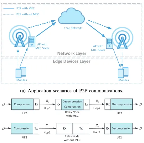
(a) Application scenarios of P2P communications.
Tx
Compression RxDecompression Tx RxDecompression Compression
Relay Node with MEC
UE1 UE2
1
R R2
Hop1 Hop2
Tx
Compression Rx Tx RxDecompression
Relay Node without MEC
UE1 UE2
1
R R2
Hop1 Hop2
D
D
D
D
[image:3.612.323.553.53.282.2](b) Computing and relaying model with and without MEC.
Fig. 1: The MEC-assisted P2P communication system.
systems. In Section V, the optimal strategies are analyzed in practical scenarios and some insights are summarized based on the analysis. The performance of the proposed model is eval-uated numerically in Section VI, followed by the conclusions in Section VII.
II. SYSTEMMODEL
Fig. 1(a) illustrates the P2P wireless communication sce-narios with and without MEC between mobile devices. In the conventional scenario, the application data, such as images or videos, are captured by the transmitting device. Then the data are compressed by the local CPU module and uploaded to the AP which serves the source device via wireless links. The AP sends the compressed data via the core network to the other AP that serves the receiving device. Finally, the receiving device decompresses it into the original application data. When the MEC servers at APs are used in the P2P communication, the compression operation in the transmitter can be offloaded to the corresponding AP, and the decompression operation in the receiver can also be performed by its AP before the downlink transmission.
The whole P2P communication architecture in Fig. 1(a) can be divided into two layers: the network layer that acts as a communication pipeline and the edge device layer that consists of mobile devices. If we assume that the transmission cost between the APs is fixed, the network layer can be modeled as a relay node. The transmitting and receiving devices are the UEs acting as the source node and the destination node, respectively. Therefore, the above P2P communication can be modeled as a computing and relaying model, as shown in Fig. 1(b). The system is described in detail as follows.
UE 1: A mobile device equipped with a computation
mod-ule and a transmitting RF modmod-ule.D bits of original data are
the local computation module by UE 1. Then the compressed data are transmitted to the relay node.
Relay Node: A wireless relay with RF and computation modules. For the conventional scenario without MEC, the relay node does not have any computing capacity in the appli-cation layer. For the MEC-assisted scenario, the compressed data are re-compressed in the relay node according to the relaying strategy. The energy of the relay node is supplied by the power grid.
UE 2: A mobile device equipped with a computation mod-ule and a receiving RF modmod-ule. UE 2 receives the compressed
data with a compression ratio ofρ2from the relay node. Then
the compressed data is decompressed to recover the original data D.
Note that the compression ratio is defined as the ratio of the uncompressed data to the compressed data. The computation and communication in the relaying system are assumed as follows.
Computation: The amount of computation (in CPU cycles)
in the UEs is related to the amount of original data D and
the compression ratio. According to [31], the CPU cycles to compress or decompress 1 bit data can be approximated as an
exponential function of the compression ratio ρi, i∈1,2as
U(ρi) =ξi(eερi−eε), (1)
where ε and ξi, i ∈ 1,2, denote constants depending on the
compression method, ρ1 is the compression ratio of UE 1
and ρ2 is the decompression ratio of UE 2. Note that ρi ∈
[1, ρmax,i],∀i∈1,2, and ρ1 may restrict the feasible solution
of ρ2 for some compression algorithms.
Communication: The compressed data D/ρi are
trans-mitted via the communication link in Hop i, i ∈ {1,2},
assumed to be a single carrier link with bandwidth B. The
wireless channels are flat fading and the channel information is
perfectly known. Letgi=|hi|2/N0denote the channel gain of
each hop withhibeing the channel response andN0being the
power spectral density of the noise. Then the communication rates (in bits/s) of each hop is given by
Ri=Blog2(1 +pigi), (2)
where pi is the transmitting power. Since the energy of the
relay node is unconstrained, p2 is assumed to be fixed.
The computation and communication in the proposed sys-tem are related via compression and decompression. In the conventional scenario without MEC, the data transmitted by the transmitter and the data received by the receiver have the
same compression ratio,i.e.,ρ1=ρ2. However, in the
MEC-assisted scenario, the compression ratios ρ1 and ρ2 can be
different,i.e.,ρ16=ρ2.
III. PERFORMANCEMETRIC
In P2P communications, users are sensitive to energy consumption and delay. This section presents the analytical expressions of energy consumption and delay based on the computation and communication models. Then, a cost function that describes the tradeoff between energy consumption and delay, is defined to assess the system performance.
A. Energy Consumption
The energy costs of all the mobile devices including UE 1 and UE 2 affect the system performance. According to (1),
the energy consumption of UE 1 to compressD bits of data
at a ratio ofρ1 is given as
Ec(ρ1) =qcDU(ρ1), (3)
whereqc (in Joule/cycle) denotes the energy consumption for
each CPU cycle. Note that DU(ρ1) (in cycles) denotes the
computation required to compressD bits of data at ρ1.
Let tTx denote the transmitting time in Hop 1. According
to (2), the energy consumption in Hop 1 is
ETx(ρ1, tTx) =p1tTx= tTx
g f
D
ρ1tTx
, (4)
wheref(x) =2
x B −1
.
Similarly, the energy consumption for the decompression in UE 2 is given by
Ed(ρ2) =qdDU(ρ2), (5)
whereqd (in Joule/cycle) denotes the energy consumption for
each CPU cycle in UE 2. According to [32], the receiving energy consumption in UE 2 is given as
ERx(ρ2) =qRx D
ρ2, (6)
whereqRx is the energy consumption for receiving each bit in
UE 2.
Other energy consumption of circuits in the UEs is assumed to be constant. Since the MEC server is connected to the power grid, its energy consumption is not taken into account here.
B. Delay
According to (1), the computing delay for the compression
of D bits with compression ratioρ1 in UE 1 is
tc(ρ1) =DU(ρ1)/fc, (7)
where fc (in cycles/s) is the CPU frequency of UE 1. The
transmission delay in Hop 1 is tTx, which depends on the
transmitting power.
Similarly, the computing delay for decompressing the
re-ceived data with a ratio of ρ2 in UE 2 can be written as
td(ρ2) =DU(ρ2)/fd, (8)
where fd (in cycles/s) is the CPU frequency of UE 2. The
reception delay in Hop 2 is
tRx(ρ2) = D
ρ2R2. (9)
Adaptive downlink power control is adopted in the relay node,
therefore the communication rate of Hop 2 R2 is controlled
by the relay node.
Although the energy consumption of the relay node can be
ignored, the computing delayTrin the relay node needs to be
considered. Note that Tr only relies on the architecture and
0 T
E1 l1:α(1)1
γ(1)
l2:α(2)1 γ(2)
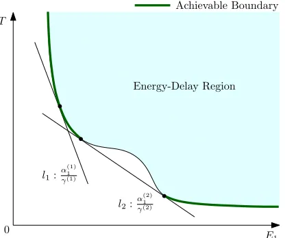
[image:5.612.73.281.56.230.2]Energy-Delay Region Achievable Boundary
Fig. 2: The achievable boundary by minimizing the weighted sum of the energy and delay.
C. Cost Function
By considering both the computation and communications, the energy consumptions of the UEs can be written as
E1=Ec(ρ1) +ETx(ρ1, tTx) +C1, (10)
E2=Ed(ρ2) +ERx(ρ2) +C2, (11)
where C1 and C2 are constants, denoting other energy
con-sumption of circuits in UE 1 and UE 2, respectively. The total
latency for the transmission ofD bits is given by
T =tc(ρ1) +tTx+Tr+tRx(ρ2) +td(ρ2). (12)
Note thatE1,E2andT all depend on the transmission and
compression strategy(tTx, ρ1, ρ2). Define the whole set of the
strategies as
S={S= (tTx, ρ1, ρ2) :tTx>0, ρi∈[1, ρmax,i],∀i∈1,2}. (13)
Based on the expressions of E1, E2 and T, we have the
achievable energy-delay region, i.e.,
R={(E1, E2, T)S :S∈ S}. (14)
The energy consumptions E1,E2 and the delay T are all
determined by the strategies. Therefore, there is a tradeoff which implies that transmitting at a higher rate with low compression rates requires more energy but reduces the delay, and vice versa. However, the optimal boundary of the energy-delay region is too complicated to obtain due to the jointly
mapping from S to R in the multi-objective problem. But
some useful boundary points can be obtained by minimizing the weighted sum over the energy consumptions and the delay, as illuminated in Fig. 2. The weighted sum represents an intrinsic energy-delay tradeoff for the proposed system. Therefore, we have the following definition.
Definition 1 (Cost Function). The cost to transmit D bits uncompressed data from UE 1 to UE 2 in the proposed computation relay system is defined as the weighted sum over the energy consumptions and the delay, i.e.,
L(tTx, ρ1, ρ2) =α1E1+α2E2+γT, (15)
whereα1,α2,γ∈[0,1]are scalar weights.
According to Definition 1, the cost function can be ex-pressed by
LMEC(tTx, ρ1, ρ2)=A1(eερ1−eε) +A2tTxe
C0
ρ1tTx +A3
ρ2 +A4(eερ2−eε)+(γ−A2)tTx+A5,
(16)
where A1 = α1qcDξ1 + γDξ1/fc, A2 = α1/g, A3 =
α2qRxD+γD/R2, A4 =α2qdDξ2+γDξ2/fd, A5=γTr+
αC1+αC2, C0=Dln 2/B.
A1 is related to the computing capacity of the transmitter,
A2 is related to the channel state information of Hop 1, A3
is related to the communication condition of Hop 2, A4 is
related to the computing capacity of the receiver andC0 is a
constant related toDand bandwidthB. Note thatA1−A4are
inversely proportional to the capacities,i.e., with an increasing
computing capacity or a stronger communication condition, the corresponding parameter decreases. The cost function is related to the transmission and compression strategy, which
consists of the transmission timetTxand the compression rates
ρ1, ρ2.
Similar, the cost function for the scenario without MEC is given by
LnoMEC(tTx,c, ρ) =(A1+A4)(eερ−eε) +A2tTx,ce
C0
ρtTx,c
+A3
ρ + (γ−A2)tTx,c+A5,
(17)
wheretTx,c is the transmitting time and ρis the compression
ratio in the scenario without MEC.
IV. OPTIMALSTRATEGIES
In this section, the optimal transmission and compression strategies for both the MEC-assisted and conventional scenar-ios are derived by minimizing the cost function.
A. MEC-assisted Scenario
Although the cost function is simplified as Equation (16),
it is still complicated to analyze due to the uncertainty inTr
and the restrictive relationship between ρ1 andρ2. Relaxing
these constraints by settingTr= 0andρ1, ρ2∈[1,+∞), the
optimization problem of minimizing the cost function is given by
P1 : min
tTx∈R+,ρ1,ρ2∈[1,+∞)
LMEC(tTx, ρ1, ρ2). (18)
We have following proposition.
Proposition 1. The optimization problemP1is jointly convex in(tTx, ρ1, ρ2).
Proof. The Hessian Matrix off(t, ρ) =teρtα is given by
H=
" α2
ρ2t3
α2
ρ3t2
α2 ρ3t2
2α ρ3 +
α2 ρ4t
#
eρtα. (19)
The determinantdet(H) = 2α3
ρ5t3e
α
ρt is positive in the support
range. Therefore, f(t, ρ) = teρtα is jointly convex in (t, ρ).
is linear, the objective function is convex. The constraints are linear. Thus the problem is convex.
Since the problem is convex, there is an optimal point
(t∗
Tx, ρ∗1, ρ∗2) to obtain the minimum cost. The necessary and
sufficient Karush-Kuhn-Tucker (KKT) conditions for the op-timal point is given by
∂L
∂t∗Tx =A2e
C0
ρ1tTx −A2C0 ρ1tTx e
C0
ρ1tTx +γ−A2= 0 (20)
∂L
∂ρ∗1 =A1εe
ερ1−A2C0 ρ2
1 e
C0
ρ1tTx = (
>0, ρ∗1= 1
= 0, ρ∗1>1 (21)
∂L ∂ρ∗
2
=A4εeερ2−A3 ρ2 2
= (
>0, ρ∗2= 1
= 0, ρ∗2>1 (22)
which leads to the following proposition.
Proposition 2. The optimal solution for P1 is given by
ρ∗1= max(1,2 εW
ε 2
r
A2C0C1 A1ε
!
) (23)
ρ∗2= max(1,2 εW
ε 2
r A3 A4ε
!
) (24)
tTx∗= C0/ρ
∗
1
WγeA−1 2 −e
−1+ 1
(25)
where C1=e
C0
(ρ1tTx)∗ andW(·)is LambertW function.
Proof. See Appendix A.
Proposition 2 presents the optimal transmission and com-pression strategy to achieve the best performance for the MEC-assisted computation relay. The succinct solution indicates that
the optimal transmitting delayt∗Txand the optimal compression
rate of the transmitter ρ∗1 are tightly coupled with each other.
Remark 1. By rearranging (25), we can find that (ρ1tTx)∗
only depends on C0 and A2. This implies that the product of compression rate and transmitting delay is a constant which is related to the channel state and the amount of transmitted data.
This remark indicates that the transmitting delay is inversely proportional to the compression rate, which agrees with the intuition that the larger the compression rate is, the fewer data the transmitter sends and the smaller the transmitting delay is. There is an optimal strategy, as shown in Proposition 2, to balance the energy consumption and the delay.
Remark 2. The optimal compression rate of Hop 2 ρ∗
2 is
independent of (t∗Tx, ρ∗1), neither the energy status and the channel state of Hop 1. In other words, the relay node decouples the compression ratios of transmitted data in the two hops, which means that the compression ratiosρ1and ρ2
can be set based on the channel and energy states of the two hops respectively.
This remark indicates a fundamental fact in the computing and relaying model that the relay node with MEC servers
breaks the communication bottleneck caused by the asymme-try of the UEs in communication and computing resources by decoupling the computation rates of the hops. However, this property may not be fully achievable due to the relationship among the compression rates, which will be further discussed in the next section.
B. Comparing with the Conventional Scenario
To further understand the computation relay, the conven-tional scenario without MEC is investigated in this subsection. Since the relay doesn’t possess the recompression ability, the compression rates of the two hops are same. The optimization problem for the conventional system is given by
P2 : min
tTx,c∈R+,ρ∈[1,+∞)
LnoMEC(tTx,c, ρ). (26)
By solving the KKT conditions of this problem, the following proposition is obtained.
Proposition 3. The problem P2 is convex. The optimal solu-tion of the system without MEC is given by
ρ∗= max 1,2 εW
ε 2
s
A2C0C1+A3 (A1+A4)ε
!!
, (27)
tTx,c∗=
C0/ρ∗
WγeA−1 2 −e
−1+ 1
. (28)
Proof. Refer to the proof of Proposition 2.
In this solution, the product of the transmitting delay and compression rate is the same as that of the MEC-assisted sys-tem. However, the compression rate depends on the parameters of both two hops. Notice that the optimal compression rate without MEC relies on the resource status of both hops, while the compression rates in the MEC-assisted system rely on the parameters of their own hop. We have the following lemma.
Lemma 1. The number(a+c)/(b+d)always lies between
a/band c/d, where a, b, c, dare both rational and positive.
Proof. Lemma 1 is obvious.
By leveraging Lemma 1, we have the following proposition.
Proposition 4. (a) We always have
ρ∗1≤ρ∗≤ρ∗2 or ρ∗2≤ρ∗≤ρ∗1. (29)
In other words, the conventional compression rate always lies between the two compression rates of the MEC-assisted system.
(b) With the same channel state information and energy status, the optimal cost of the MEC-assisted system is always less than the optimal cost of the conventional system, namely
LnoMEC(t∗Tx,c, ρ∗)≥LMEC(tTx∗, ρ∗1, ρ∗2). (30)
Proof. (a) Since the Lambert W function monotonically
in-creases in domainR+,f(x) = 2εW(
ε
2 √
x)also monotonically
increases in domain R+. Combining with Lemma 1, the
(b) This proposition easily follows by contradiction since
the optimization problem P2 can be rewritten as
min
tTx∈R+,ρ1,ρ2∈[1,+∞)
LMEC(tTx, ρ1, ρ2)
s.t. ρ1=ρ2,
(31)
which is the optimization problem P1 with an equality
con-straint.
Proposition 4 (a) reveals that the MEC server decouples the compression rates of the two hops. Via recompressing in the MEC server, the computing and relaying model releases the restriction on the compression rates caused by the limited computing and communication resources in the opposite hop. The restriction brings the extra cost in the conventional system, which is significantly slacked by the computing and relaying model. Proposition 4 (b) shows the original intention of the
computing and relaying model ,i.e., reducing the cost in P2P
communications.
C. Special Cases
The above analysis gives some general solutions to the MEC-assisted and conventional P2P communication systems. Furthermore, it is valuable to investigate when the available computing and communication resources turns to extremely poor. To discuss these special cases, we have the following definition first.
Definition 2 (Cost Difference). The cost difference between the conventional and MEC-assisted systems is defined as
Gdiff=LnoMEC(tTx,c, ρ)−LMEC(tTx, ρ1, ρ2). (32)
Then the cost differences for various special cases are written as follows.
Case 1 (Poor Computing Capacity in UE 1):When the
computing capacity in UE 1 is extremely insufficient,i.e., the
CPU frequency is low and the energy consumption for each cycle is high, UE 1 should not compress the original data.
Therefore, we have ρ1 = ρ = 1 and tTx = tTx,c. The cost
difference is given by
Gdiff=A3
1− 1 ρ2
+A4(eε−eερ2). (33)
In practice, UE 1 represents the IoT devices like sensors with simple circuit configurations and powered by low-energy batteries. The sensed data are supposed to be transmitted to the MEC servers for postprocessing such as compression.
Case 2 (Poor Computing Capacity in UE 2):The expected decompression rate of UE 2 reaches 1, when the computing
capacity of UE 2 is very insufficient. Then we haveρ2=ρ=
1. The cost difference is given by
Gdiff= (γ−A2+A2C1)X
1− 1 ρ1
+A1(eε−eερ1), (34)
where X = (ρtTx,c) = (ρ1tTx) = C0
WγeA−1
2 −e
−1+1. This
case will be common in the future since lighter terminal is
the development tendency and all major computation will be offloaded to the MEC servers.
Case 3(Poor Communication Condition in Hop 1):When the wireless channel of Hop 1 experiences a deep fade, UE 1 must make its best effort to compress the original data to decrease
the communication burden. Then we have ρ1 = ρ = ρmax,1
andtTx=tTx,c. The cost difference is given by
Gdiff=A3 1
ρ− 1 ρ2
+A4(eρε−eερ2). (35)
Due to the uncertainty of the wireless environment, Case 3 is likely to occur and so is Case 4.
Case 4(Poor Communication Condition in Hop 2):When the wireless channel of Hop 2 experiences a deep fade and the energy consumption of UE 2 for receiving each bit is large, the data stream of Hop 2 should be compressed with the best effort of the system. Thus, the compression ratios of the MEC-assisted and conventional systems are assumed to be set to the
largest and same value, namely ρ2 = ρ = ρmax,2. The cost
difference is given by
Gdiff= (γ−A2+A2C1)X
1 ρ−
1 ρ1
+A1(eερ−eερ1). (36)
In these cases, only one of the compression rates affects the cost difference. Therefore, we can derive the optimal solutions
by maximizingGdiff. According to (33) (34) (35) and (36), a
universal formula is concluded as
g(x) =a− b x−ce
εx, (37)
which has the following closed-form optimal solution.
Lemma 2. If x∈ R+, then g(x) is concave. The maximum
value is obtained when
x∗=2 εW
ε 2
r b εc
!
. (38)
Proof. Since−b
x and−e
εx are both concave inx∈
R+, the
linear sum g(x)is concave. Then solvingg0(x) = 0 leads to
the lemma.
Thus we have the following proposition.
Proposition 5. The cost difference for Case 1 and 3 reaches the maximum when
ρ∗2= max 1, 2 εW
ε 2
r A3 A4ε
!!
. (39)
The compression rate ρ1 equals 1 or ρmax, respectively. For
Case 2 and 4, the cost difference reaches the maximum when
ρ∗1= max(1,2 εW
ε 2
s
(γ−A2+A2C1)X A1ε
). (40)
The compression rateρ2 equals 1 orρmax, respectively.
Proof. According to Lemma 2, the solution to the problem
P3 : max
ρ1(2)∈[1,+∞)
G
diff
0 1 ρ ρ∗1(ρ∗2) ρ1(ρ2)
Case 1, 2 Case 3, 4
x∗
(a) Solution when the communication cost dominates.
G
diff
0 1 ρ ρ1(ρ2)
ρ∗1(ρ∗2)
Case 1, 2 Case 3, 4
x∗
[image:8.612.75.542.54.163.2](b) Solution when the computing cost dominates.
Fig. 3: Solutions to the special cases.
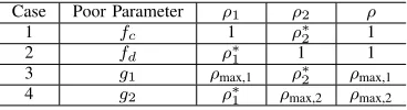
Case Poor Parameter ρ1 ρ2 ρ
1 fc 1 ρ∗2 1
2 fd ρ∗1 1 1
3 g1 ρmax,1 ρ∗2 ρmax,1
4 g2 ρ∗1 ρmax,2 ρmax,2
TABLE I: Solutions to the special cases.
is easy to obtain.
The solution is illuminated in Fig. 3. When the
communica-tion cost dominates,x∗is obtained in the feasible region. But
when the computing cost dominates, x∗ is located before 1
andρ∗1(ρ∗2) = 1is the optimal solution. The proposed solution is summarized in Table I. By rearranging (40), we find that the above result gives the same solution as Proposition 2. In the four special cases, the transmission and compression strategy for the conventional system is fixed due to the poor parameters. According to (33) and (35), the cost difference will be larger if the communication condition of Hop 2 is worse and the computing capacity of UE 2 is stronger in Case 1 and Case 3. According to (34) and (36), the cost difference will be larger if the communication condition of Hop 1 is worse and the computing capacity of UE 1 is stronger in Case
2 and Case 4. Note that A1−A4 are inversely proportional
to their corresponding capacities as mentioned in Section III. Therefore, we have the following remark.
Remark 3. The improvement provided by the MEC-assisted relay node is determined by the strength of the computation and communication asymmetry of the UEs. For example, if A1 << A2 and A3 << A4, we will see a massive
improvement.
V. ANALYSIS INPRACTICALSCENARIOS
A general solution for the MEC-assisted P2P communi-cation is presented in the last section. In this section, some practical scenarios are further analyzed, including the restric-tive relationship among the compression ratios, the DVFS technique probably adopted in the UEs and the computing delay in the MEC server.
A. Compression Ratio Constraints
Some compression algorithms are lossless and others are lossy. For example, most video compression algorithms are
lossy. A lossy compression algorithm leads to loss of infor-mation, thus only a small compression rate is available in the MEC server.
For the lossless compression, there is no restrictive relation-ship among compression ratios. Hence, the optimal solution for the lossless compression is given by
ρ∗∗1 = min(ρ∗1, ρmax,1)
ρ∗∗2 = min(ρ∗2, ρmax,2)
t∗∗Tx=X/ρ∗∗1
, (42)
whereρmax,i,∀i= 1,2 is the maximum compression rate of
UEidepending on its computing capacity,ρ∗∗i ,∀i= 1,2is the
optimal compress rate,t∗∗
Tx is the optimal transmitting strategy
after considering the maximum compression rates.
For lossy compression, ρ2 is required to be not less than
ρ1. Hence ρ∗1∗ is the lower boundary of ρ∗2, i.e., ρ∗2 =
max(ρ∗∗1 , ρ∗2). To access the quality of experience (QoE) influence of lossy compression, different metrics have been proposed for different types of media data. But to derive a more universal conclusion, the perceiving quality of users for lossy compression in the proposed model is simply bounded
by the maximum compression rate ρmax. If the compression
rate is larger thanρmax, the perceiving quality is unacceptable
at the receiver. Note that the solution degrades into Case 1 if
ρmax,1 equals 1 and degrades into Case 2 ifρmax,2 equals 1.
B. DVFS Technique
Assume that the DVFS technique is utilized in the proposed MEC-assisted P2P communication model. The UEs can dy-namically adjust the CPU’s computational frequency to adopt
the power consumption and execution latency. For UE i, the
computational powerpi can be modeled as
pi =fiκζi, (43)
wherefi, in unit of Hz, is the CPU’s computational frequency
of user i and ζi > 0 is the effective capacitance coefficient
depending on chip architecture. The value κ (κ ≥ 2) is a
constant [33]. For simplicity, we set κ= 2 and assume that
the local CPU is a single core architecture with a frequency
upper bound offmax,i. Thus, the computational power satisfies
[image:8.612.83.267.214.264.2]Thus, the energy consumption of UE 1 to compress Dbits
of data at a ratio ofρ1 is given by
Ec(ρ1) =qcDU(ρ1) =p1tc(ρ1)
=fc2ζ1DU(ρ1) fc
=Dζ1fcU(ρ1),
(44)
where fc is the dynamic frequency of UE 1, U(ρ1) is the
CPU cycles to compress or decompress 1 bit data at ρ1.
Therefore, the energy consumption for each CPU cycle qc(d)
(in Joule/cycle) can be rewritten as
qc(d)=fc(d)ζ1(2). (45)
Therefore, we have
A1=α1ζ1Dξ1fc+
γDξ1 fc
,
A4=α2ζ2Dξ2fd+
γDξ2 fd
.
(46)
Since the functionf(x) =ax+b
x reaches the minimum2
√ ab
when x=qb
a, the minima of A1 andA4 are easy to derive.
Note that the dynamic frequencies don’t affect the optimization
problem of minimizing the cost function LMEC(tTx, ρ1, ρ2),
therefore the optimal solution in Proposition 2 still applies.
C. MEC Server Constraint
In practical scenarios, Proposition 4 (b) doesn’t always hold. The optimal cost of the MEC-assisted system isn’t always less than the conventional P2P communication due to the existence of computing delay in the MEC server. The computing capacity of the server is higher than that of devices but is still limited. Hence the computation in servers occupies time and causes delay to the P2P communication. The MEC server may decompress the transmitted data and re-compress it or may just re-compress it directly to the target ratio and the computing process may occupy one thread or multi-thread. Therefore, the computing delay in the server is quite complicated. Here, the influence of the computing delay in the server is analyzed by comparing it with the cost difference offered by the optimal relaying strategy. The desired solution
withT ris written as
(ρ∗∗1 , ρ∗∗2 , t∗∗Tx) = (
(ρ∗1, ρ∗1, t∗Tx) γTr< G∗diff
(ρ∗, ρ∗, t∗Tx,c) γTr≥G∗diff,
(47)
whereG∗diff=LnoMEC(t∗Tx,c, ρ∗)−LMEC(t∗Tx, ρ∗1, ρ∗2).
D. Energy and Delay Constraints
In many practical scenarios, the energy consumption or the latency of the P2P communication system is limited. When the system delay is constrained, the optimal strategy can be obtained by minimizing the energy consumption, which is written as
min
tTx,ρ1,ρ2
α1E1(ρ1, tTx) +α2E2(ρ2)
s.t. T(tTx, ρ1, ρ2)≤TC,
(48)
whereTC is the delay constraint for the transmission of data
D. When the energy consumption of the UEs is constrained,
the optimization problem degrades into
min
tTx,ρ1,ρ2
T(tTx, ρ1, ρ2)
s.t. E1(ρ1, tTx)≤ES,
E2(ρ2)≤ER,
(49)
where ES and ER are the energy constraints in the UEs to
transmit the D bits data from UE 1 to UE 2.
As proved in Proposition 1, the Hessian Matrix off(t, ρ) =
teρtα is positive in the support range, thus it is jointly convex
in (t, p). Therefore (4) is jointly convex in (tTx, ρ1). Since
(5), (6), (7), (8) and (9) are all convex inρ1orρ1, the energy
consumptionE1(tTx, ρ1),E2(ρ2)and the delayT(tTx, ρ1, ρ2)
are all convex functions. Therefore, (48) and (49) are convex problems.
The two problems have a mutual Lagrange function, which is given by
L(tTx, ρ1, ρ2, γ, α1, α2) =α1E1+α2E2+γT +C. (50)
Note that for (48) the Lagrange multipliers α1 and α2 are
fixed to 1 and C = γ(Tr−T), and for (49) the Lagrange
multiplierγis fixed to 1 and C=Tr−α1ES−α2ER. It can
be found that the mutual Lagrange functionL is very similar
with the cost functionL, and solvingLwith the necessary and
sufficient KKT conditions leads to Proposition 2. However, the unfixed Lagrange multipliers in the optimal solution need to be updated according to the dual problems. The dual problems are written as
max D1(γ)
s.t. γ≥0, (51)
max D2(α1, α2)
s.t. α1≥0, α2≥0, (52)
whereD1(2) = min
tTx,ρ1,ρ2
L. Since the objective function of the
dual problem is linear in the Lagrange multipliers, the dual problem is convex, and the Lagrange multipliers can be solved by subgradient projection method. The Lagrange multipliers are updated as follows:
∆γ=T−T(t∗Tx, ρ∗1, ρ∗2),
∆α1=ES−E1(ρ∗1, t∗Tx),
∆α2=ER−E2(ρ∗2),
γ(t+ 1) = [γ(t)−τ1(t)∆γ(t)] +
,
αi(t+ 1) = [αi(t)−τ2(t)∆αi(t)]
+
, ∀i∈ {1,2},
(53)
wheret is the iteration index, τ1(t), τ2(t) are step sizes. By
updating γ and αi using the above equations, the specific
algorithm for this problem is summarized as Algorithm 1. The algorithm gives an iterative framework to solve the energy (or delay) minimization problems with fixed delay (or energy) constraints. The general solution for the computation relay is utilized directly to deal with these practical scenarios after considering the computing delay in the server and the restriction among the compression rates. Although the optimal solution (ρ∗
Algorithm 1 Iterative algorithm for the computing and relay-ing model with energy or delay constraints
1: Initialize:
Set t= 0 andtmax is the maximum number
of iterations. Set γ(t)(orα1(t),α2(t)) and
allowable errorδ.
2: repeat
3: Calculate (ρ∗1, ρ∗2, t∗Tx)according to Proposition 2.
4: Update γ(t+ 1)(or αi(t+ 1)∀i∈1,2) from (53).
5: if kγ(t+ 1)−γ(t)k2< δ
(or kαi(t+ 1)−αi(t)k2< δ) then
6: Close.
7: end if
8: t=t+ 1.
9: untilt > tmax.
2, it can be unconditionally replaced by (ρ∗1, ρ∗2, t∗Tx) if the compression ratio constraints or MEC server constraints are given.
Although the proposed computing and relaying system is analyzed under several strong assumptions, some valuable in-sights can be obtained for using MEC in practical applications. First, it is suitable to utilize the MEC server to promote the data throughput capacity in P2P communication systems, especially when the communication and computing resources in the two relaying hops are asymmetric. Second, when the computation operation, such as compression, is dividable, we can obtain a remarkable transmission gain by distributing the computation among the communication components that have enough computing capacity. Even if considering the possible energy and delay cost in the MEC server, the gain is available and affordable. Third, to better deal with the data computation and transmission problems, the computing and communication resources distributed among the networks should be properly integrated.
-20 -15 -10 -5 0 5 10 15 20
Channel Gain of Hop 2 (dB) 0
0.1 0.2 0.3 0.4 0.5 0.6
Cost Difference
fc = 500 MHz, fd = 200 MHz
[image:10.612.52.296.81.233.2]fc = 10 MHz, fd = 1 GHz
Fig. 4: Cost difference with the increasing channel gain of Hop 2.
VI. NUMERICALRESULTS ANDDISCUSSION
In this section, we evaluate the performance of the proposed computing and relaying model. To better show the system performance, the cost gain is defined as the ratio of the cost functions of the MEC-assisted system and the conventional system,i.e.,
Cost Gain= LMEC
LnoMEC
, (54)
which is always less than 1 according to Proposition 4. Note that a smaller gain ratio represents better performance. The cost gain is more appropriate for the numerical evaluation than the cost difference defined by (32), since the cost difference varies dramatically with different parameters, as shown in Fig. 4. The computing and relaying model comprises one MEC
relay node and two UEs, where UE 1 transmits D bits data
to UE 2 through the MEC relay node. The amount of dataD
is set to 1024 bits and the bandwidth is 15kHz to simulate the peer-peer communication between IoT devices. The utility
weights of the cost function areγ= 0.5/Sec,α1= 0.25/Joul
and α2 = 0.25 /Joul. The energy consumption for receiving
each bit in the receiver isqRx= 0.42×10⁻⁶ J/bits according
to Tale 1 of [32]. For the data compression, the required numbers of CPU cycles for compression and decompression
ξ1, ξ2 belong to [0,3000] cycles/bit respectively, the
CPU-cycle frequency is fc(d) ∈ [100,1000] MHz, and the energy
consumption per cycle isqc(d)= 1×10⁻¹³Joul/bit by default.
We set the maximum compression ratio ρmax = 5, ε = 0.5,
and other energy consumptions C1 andC2 to 0.
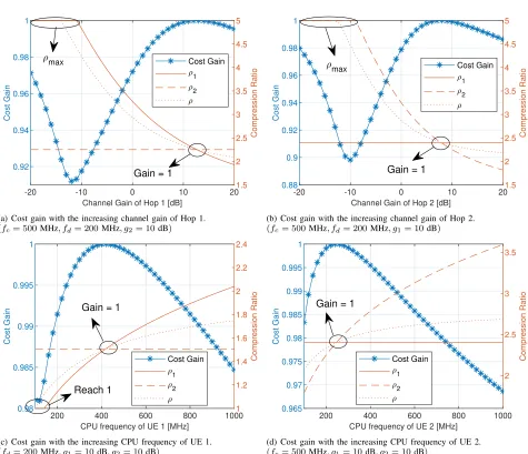
Fig. 5 illustrates the performance gain with different channel gains of the Hops or different CPU frequencies of the UEs. In the figure, the left y-axis represents to the gain provided by the computing and relaying model and the right y-axis represents to the optimal compression rates. Note that the compression
rate is limited to[1,5]and the transmitting power of the relay
node is set to 1 W. In these figures, we find that there is always a balance point where the performance gain equals 1
and ρ = ρ1 = ρ2. At this point, the MEC server doesn’t
work at all, and the computing and communication resources before the relay node and after the relay node are symmetric and balanced. When the channel state or the CPU frequency varies, the balance is broken and the MEC server participates in the communication. However, the cost gain line doesn’t always turn down forward or backward from the balance point due to the maximum and minimum limits to the compression
rate. Furthermore, it is observed that ρis always betweenρ1
andρ2 in all the figures, which verifies Proposition 4. Notice
[image:10.612.62.291.524.696.2]that the performance gains in Fig. 5 are quite small, because the evaluation parameters are selected to show the balanced points.
Fig. 6 shows the performance gain of the proposed system with the channel gains of Hop 1 and Hop 2. In Fig. 6 (a), the parameters of UE 1 and Hop 1 are investigated while
the parameters of UE 2 and Hop 2 are fixed, i.e. fd = 1
Ghz, qd = 1×10⁻¹³ and g2 = −10 dB. It indicates that
the computing and relaying model obtains better gain when the computing capacity of UE 1 is lower, the energy efficient
-20 -10 0 10 20 Channel Gain of Hop 1 [dB]
0.92 0.94 0.96 0.98 1
Cost Gain
1.5 2 2.5 3 3.5 4 4.5 5
Compression Ratio
Cost Gain
1
2
Gain = 1
max
(a) Cost gain with the increasing channel gain of Hop 1.
(fc= 500MHz, fd= 200MHz, g2= 10dB)
-20 -10 0 10 20
Channel Gain of Hop 2 [dB] 0.88
0.9 0.92 0.94 0.96 0.98 1
Cost Gain
1.5 2 2.5 3 3.5 4 4.5 5
Compression Ratio
Cost Gain
1
2
Gain = 1
max
(b) Cost gain with the increasing channel gain of Hop 2.
(fc= 500MHz, fd= 200MHz, g1= 10dB)
200 400 600 800 1000
CPU frequency of UE 1 [MHz] 0.98
0.985 0.99 0.995 1
Cost Gain
1 1.2 1.4 1.6 1.8 2 2.2 2.4
Compression Ratio
Cost Gain
1
2
Gain = 1
Reach 1
(c) Cost gain with the increasing CPU frequency of UE 1.
(fd= 200MHz, g1= 10dB, g2= 10dB)
200 400 600 800 1000
CPU frequency of UE 2 [MHz]
0.965 0.97 0.975 0.98 0.985 0.99 0.995 1
Cost Gain
2 2.5 3 3.5
Compression Ratio
Cost Gain
1
2
Gain = 1
(d) Cost gain with the increasing CPU frequency of UE 2.
[image:11.612.68.543.54.463.2](fc= 500MHz, g1= 10dB, g2= 10dB)
Fig. 5: The performance gain with the increasing channel gains and CPU frequencies.
-20 -15 -10 -5 0 5 10 15 20
Channel Gain of Hop 1 (dB) 0.5
0.6 0.7 0.8 0.9 1
Cost Gain
fc = 1 GHz, qc = 1 10-13
fc = 100 MHz, qc = 1 10-8
fc = 100 MHz, qc = 1 10-13
(a) Cost gain with the increasing channel gain of Hop 1.
-20 -15 -10 -5 0 5 10 15 20
Channel Gain of Hop 2 (dB) 0.65
0.7 0.75 0.8 0.85 0.9 0.95 1
Cost Gain
fd = 1 GHz, qd = 1 10-13 fd = 100 MHz, qd = 1 10-8
fd = 100 MHz, qd = 1 10-13
(b) Cost gain with the increasing channel gain of Hop 2.
[image:11.612.79.543.525.699.2]0 5 10 15 20 25
/ 0.006
0.008 0.01 0.012 0.014 0.016 0.018 0.02 0.022
Time /Second
Our Time Cost Conventional Time Cost
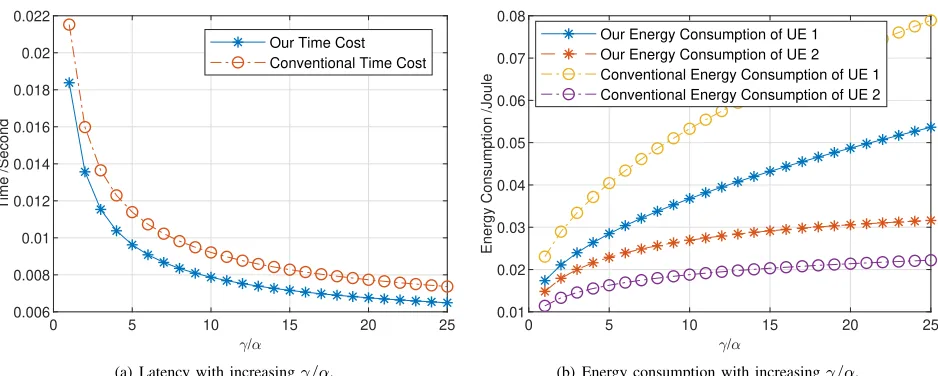
(a) Latency with increasingγ/α.
0 5 10 15 20 25
/ 0.01
0.02 0.03 0.04 0.05 0.06 0.07 0.08
Energy Consumption /Joule
Our Energy Consumption of UE 1 Our Energy Consumption of UE 2 Conventional Energy Consumption of UE 1 Conventional Energy Consumption of UE 2
[image:12.612.73.542.53.241.2](b) Energy consumption with increasingγ/α.
Fig. 7: The latency and the energy consumption of the P2P communication with increasingγ/α. Frequency of UE 1 2.3GHz,
frequency of UE 2 200MHz, average channel gain of Hop 1 -10dB, average channel gain of Hop 2 10dB, size of D1024bits.
gain. In Fig. 6 (b), the parameters of UE 1 and Hop 1 are
fixed to fc = 100 Mhz, qd = 1×10⁻¹³ and g2 = 10 dB.
It is observed that, when the computation parameter of UE 2 turns better and the channel gain of Hop 2 turns worse, the performance gain increases before reaching the boundary of compression rate. This figure verifies that the MEC server makes a great contribution to the P2P communication system especially when the computing and communication resources are imbalanced among hops, which always exists in mobile scenes.
Fig. 7 gives the latency and the energy consumption with
increasing γ/α in a practical P2P communication scenario,
where a wearable sensor sends a message to a remote mobile
phone. The message size D is fixed to 1024bits. The CPU
frequency of the sensor CPU is set to 200MHz and that of the mobile phone is set to 2.3GHz. The other parameters are set as default. The average channel gain from the sensor to the AP node is -10dB and the average channel gain from the AP node (different from the one that serves the sensor) to the mobile
phone is set to 10dB.γandα=α1=α2 are weights of time
cost and energy consumption respectively. A larger ratioγ/α
represents less delay but more energy consumption. Monte Carlo simulation results with 10000 channel realizations are given in the figure. As we can see, the computing and relaying strategy obtains less time cost compared to the conventional strategy in Fig. 7 (a). In Fig. 7 (b), although our strategy brings less energy consumption for the sensor (UE 1), but results in more energy consumption for the mobile phone (UE 2). However, since the sensor is much more sensitive in energy than the mobile, the computing and relaying strategy can significantly extend the battery life of sensors and meanwhile reduce the latency of P2P communications.
VII. CONCLUSION
In this paper, we have proposed a novel computing and relaying model, in which an MEC server plays the role of the relay node to enhance the data throughput of P2P
communications. By minimizing the cost function that consists of the energy consumption and latency, the optimal trans-mission and compression strategies for the MEC-assisted and conventional systems have been derived respectively. Then we have further considered some practical scenarios and have presented a specific algorithm for the systems with energy or delay constraints. Numerical results verify the efficiency of the proposed system. Our analysis indicates that the MEC theory can be utilized to promote P2P communications, and a lower latency and higher energy-efficiency P2P communication sys-tem can be achievable by jointly dispatching the computing and communication resources distributed in the network.
APPENDIXA
The relation in (20) can be rearranged as
C0
ρ1tTx −1
e
C0
ρ1tTx−1=
γ
A2 −1
e−1, (55)
which has the form ofx=W(x)eW(x). Therefore, we have
C0 ρ1tTx
−1 =W γe−1
A2 −e−1
, (56)
whereW(·)is LambertW function. Then we obtain
(ρ1tTx)
∗
= C0
WγeA−1 2 −e
−1+ 1
. (57)
Set C1 = e
C0
(ρ1tTx)∗, and (21) can be rearranged in the W
function form as
ερ1 2 e
ερ1 2 =ε
2 r
A2C0C1
A1ε . (58)
By solving the combined equations of (57) (58), we can obtain
tTx∗ andρ∗1.
Similarly, the relation in (22) leads to
ερ2 2 e
ερ2 2 = ε
2 r
A3
A4ε, (59)
which finally givesρ∗
REFERENCES
[1] V. Cisco, “Cisco visual networking index: Forecast and trends, 2017–2022,”White Paper, Nov. 2018.
[2] P. Mach and Z. Becvar, “Mobile edge computing: A survey on architecture and computation offloading,”IEEE Commun. Surv.
Tutorials, vol. 19, no. 3, pp. 1628–1656, Mar. 2017.
[3] Y. Mao, C. You, J. Zhang, K. Huang, and K. B. Letaief, “A survey on mobile edge computing: The communication perspective,”IEEE Commun. Surv. Tutorials, vol. 19, no. 4, pp. 2322–2358, 4th Quart. 2017.
[4] N. Abbas, Y. Zhang, A. Taherkordi, and T. Skeie, “Mobile edge computing: A survey,” IEEE Internet Things J., vol. 5, no. 1, pp. 450–465, Feb 2018.
[5] S. Wang, X. Zhang, Y. Zhang, L. Wang, J. Yang, and W. Wang, “A survey on mobile edge networks: Convergence of computing, caching and communications,”IEEE Access, vol. 5, pp. 6757– 6779, Mar 2017.
[6] F. Bonomi, R. Milito, J. Zhu, and S. Addepalli, “Fog computing and its role in the internet of things,” inProc. ACM Workshop
on Mobile Cloud Computing (MCC). ACM, Aug. 2012, pp.
13–16.
[7] M. Patel, B. Naughton, C. Chan, N. Sprecher, S. Abeta, A. Neal
et al., “Mobile-edge computing introductory technical white
paper,” White Paper, Mobile-edge Computing (MEC) industry
initiative, Sep. 2014.
[8] Y. C. Hu, M. Patel, D. Sabella, N. Sprecher, and V. Young, “Mobile edge computing - a key technology towards 5G,”ETSI
white paper, vol. 11, no. 11, pp. 1–16, 2015.
[9] T. X. Tran, P. Pandey, A. Hajisami, and D. Pompili, “Collab-orative multi-bitrate video caching and processing in mobile-edge computing networks,” in Proc. 13th Annual Conference
on Wireless On-demand Network Systems and Services (WONS),
Feb 2017, pp. 165–172.
[10] S. Mangiante, G. Klas, A. Navon, Z. GuanHua, J. Ran, and M. D. Silva, “VR is on the edge: How to deliver 360 videos in mobile networks,” inProc. the Workshop on Virtual Reality and
Augmented Reality Network. ACM, Aug. 2017, pp. 30–35.
[11] H. Rahman, R. Rahmani, and T. Kanter, “The role of mobile edge computing towards assisting IoT with distributed intel-ligence: A smartliving perspective,” in Mobile Solutions and
Their Usefulness in Everyday Life. Springer, 2019, pp. 33–45.
[12] Y. Wang, M. Sheng, X. Wang, L. Wang, and J. Li, “Mobile-edge computing: Partial computation offloading using dynamic voltage scaling,” IEEE Trans. Commun., vol. 64, no. 10, pp. 4268–4282, Oct. 2016.
[13] Y. Mao, J. Zhang, and K. B. Letaief, “Dynamic computation offloading for mobile-edge computing with energy harvesting devices,” IEEE J. Sel. Areas Commun., vol. 34, no. 12, pp. 3590–3605, Dec. 2016.
[14] W. Zhang, Y. Wen, K. Guan, D. Kilper, H. Luo, and D. O. Wu, “Energy-optimal mobile cloud computing under stochastic wireless channel,” IEEE Trans. Wireless Commun., vol. 12, no. 9, pp. 4569–4581, Sep. 2013.
[15] S. Ulukus, A. Yener, E. Erkip, O. Simeone, M. Zorzi, P. Grover, and K. Huang, “Energy harvesting wireless communications: A review of recent advances,” IEEE J. Sel. Areas Commun., vol. 33, no. 3, pp. 360–381, Mar. 2015.
[16] T. Q. Dinh, J. Tang, Q. D. La, and T. Q. S. Quek, “Offloading in mobile edge computing: Task allocation and computational frequency scaling,” IEEE Trans. Commun., vol. 65, no. 8, pp. 3571–3584, Aug. 2017.
[17] C. You and K. Huang, “Exploiting non-causal cpu-state in-formation for energy-efficient mobile cooperative computing,”
IEEE Trans. Wireless Commun., vol. 17, no. 6, pp. 4104–4117,
June 2018.
[18] C. You, K. Huang, H. Chae, and B. Kim, “Energy-efficient resource allocation for mobile-edge computation offloading,”
IEEE Trans. Wireless Commun., vol. 16, no. 3, pp. 1397–1411,
Mar. 2017.
[19] C. Wang, F. R. Yu, C. Liang, Q. Chen, and L. Tang, “Joint com-putation offloading and interference management in wireless cellular networks with mobile edge computing,” IEEE Trans.
Veh. Technol., vol. 66, no. 8, pp. 7432–7445, Aug. 2017.
[20] C. Wang, C. Liang, F. R. Yu, Q. Chen, and L. Tang, “Com-putation offloading and resource allocation in wireless cellular networks with mobile edge computing,”IEEE Trans. Wireless
Commun., vol. 16, no. 8, pp. 4924–4938, Aug. 2017.
[21] Z. Tan, F. R. Yu, X. Li, H. Ji, and V. C. M. Leung, “Virtual resource allocation for heterogeneous services in full duplex-enabled SCNs with mobile edge computing and caching,”IEEE
Trans. Veh. Technol., vol. 67, no. 2, pp. 1794–1808, Feb. 2018.
[22] M. Qin, L. Chen, N. Zhao, Y. Chen, F. R. Yu, and G. Wei, “Power-constrained edge computing with maximum processing capacity for IoT networks,”IEEE Internet of Things Journal, pp. 1–1, 2018, early access.
[23] K. C. Barr and K. Asanovi´c, “Energy-aware lossless data compression,”ACM Trans. Comput. Syst. (TOCS), vol. 24, no. 3, pp. 250–291, Aug. 2006.
[24] S. Khan, Y. Peng, E. Steinbach, M. Sgroi, and W. Kellerer, “Application-driven cross-layer optimization for video stream-ing over wireless networks,” IEEE Commun. Mag., vol. 44, no. 1, pp. 122–130, Jan. 2006.
[25] M. van Der Schaar et al., “Cross-layer wireless multimedia transmission: challenges, principles, and new paradigms,”IEEE
Wireless Commun., vol. 12, no. 4, pp. 50–58, Aug. 2005.
[26] A. Passarella, “A survey on content-centric technologies for the current internet: Cdn and p2p solutions,” Comput. Commun., vol. 35, no. 1, pp. 1–32, Jan. 2012.
[27] Z. Liu, Y. Shen, K. W. Ross, S. S. Panwar, and Y. Wang, “LayerP2P: Using layered video chunks in P2P live streaming,”
IEEE Trans. Multimedia, vol. 11, no. 7, pp. 1340–1352, Nov.
2009.
[28] A. Detti, B. Ricci, and N. Blefari-Melazzi, “Peer-to-peer live adaptive video streaming for information centric cellular net-works,” inProc. IEEE PIMRC’13, Sep. 2013, pp. 3583–3588. [29] B. Nazer and M. Gastpar, “Compute-and-forward: Harnessing
interference through structured codes,” IEEE Transactions on
Information Theory, vol. 57, no. 10, pp. 6463–6486, 2011.
[30] R. M. Corless, G. H. Gonnet, D. E. Hare, D. J. Jeffrey, and D. E. Knuth, “On the lambertw function,”Advances in Computational
mathematics, vol. 5, no. 1, pp. 329–359, 1996.
[31] X. Li, C. You, S. Andreev, Y. Gong, and K. Huang, “Optimizing wirelessly powered crowd sensing: Trading energy for data,” in
Proc. IEEE ICC Workshops, May 2018, pp. 1–6.
[32] L. M. Feeney, “An energy consumption model for performance analysis of routing protocols for mobile ad hoc networks,”
Mobile Networks and Applications, vol. 6, no. 3, pp. 239–249,
Jun. 2001.
[33] M. E. Gerards, J. L. Hurink, and J. Kuper, “On the interplay between global DVFS and scheduling tasks with precedence constraints,”IEEE Trans. Comput., vol. 64, no. 6, pp. 1742– 1754, Jun. 2015.
Min Qin received the B.S. from the Department
Li Chenreceived the B.E. in electrical and
informa-tion engineering from Harbin Institute of Technol-ogy, Harbin, China, in 2009 and the Ph.D. degree in electrical engineering from the University of Science and Technology of China, Hefei, China, in 2014. He is currently a faculty member with the Department of Electronic Engineering and Information Science, University of Science and Technology of China. His research interests include wireless IoT communica-tions and wireless optical communicacommunica-tions.
Nan Zhao(S’08-M’11-SM’16) is currently an
Asso-ciate Professor at Dalian University of Technology, China. He received the B.S. degree in electronics and information engineering in 2005, the M.E. de-gree in signal and information processing in 2007, and the Ph.D. degree in information and commu-nication engineering in 2011, from Harbin Institute of Technology, Harbin, China. His recent research interests include UAV Communications, Interference Alignment, and Physical Layer Security.
Dr. Zhao is serving or served on the editorial boards of 7 SCI-indexed journals. He received Top Reviewer Award from IEEE Transactions on Vehicular Technology in 2016, and was nominated as an Exemplary Reviewer by IEEE Communications Letters in 2016. He won the best paper awards in IEEE VTC’2017-Spring and MLICOM 2017.
Yunfei Chen(S’02-M’06-SM’10) received his B.E.
and M.E. degrees in electronics engineering from Shanghai Jiaotong University, Shanghai, P.R.China, in 1998 and 2001, respectively. He received his Ph.D. degree from the University of Alberta in 2006. He is currently working as an Associate Professor at the University of Warwick, U.K. His research interests include wireless communications, cognitive radios, wireless relaying and energy harvesting.
F. Richard Yu (S’00-M’04-SM’08-F’18) received
the PhD degree in electrical engineering from the University of British Columbia (UBC) in 2003. From 2002 to 2006, he was with Ericsson (in Lund, Sweden) and a start-up in California, USA. He joined Carleton University in 2007, where he is cur-rently a Professor. He received the IEEE Outstanding Service Award in 2016, IEEE Outstanding Leader-ship Award in 2013, Carleton Research Achievement Award in 2012, the Ontario Early Researcher Award (formerly Premiers Research Excellence Award) in 2011, the Excellent Contribution Award at IEEE/IFIP TrustCom 2010, the Leadership Opportunity Fund Award from Canada Foundation of Innovation in 2009 and the Best Paper Awards at IEEE ICNC 2018, VTC 2017 Spring, ICC 2014, Globecom 2012, IEEE/IFIP TrustCom 2009 and Int’l Conference on Networking 2005. His research interests include wireless cyber-physical systems, connected/autonomous vehicles, security, distributed ledger technology, and deep learning.
He serves on the editorial boards of several journals, including Co-Editor-in-Chief for Ad Hoc &Sensor Wireless Networks, Lead Series Editor for IEEE Transactions on Vehicular Technology, IEEE Transactions on Green Communications and Networking, and IEEE Communications Surveys &
Tutorials. He has served as the Technical Program Committee (TPC) Co-Chair of numerous conferences. Dr. Yu is a registered Professional Engineer in the province of Ontario, Canada, a Fellow of the Institution of Engineering and Technology (IET), and a Fellow of the IEEE. He is a Distinguished Lecturer, the Vice President (Membership), and an elected member of the Board of Governors (BoG) of the IEEE Vehicular Technology Society.
Guo Wei received the B.S. degree in electronic