5200
Computer Unit
.
400690
CONTENTS Diagnostics
Fault Location
Power Supply Module Voltages and Adjustment
Removing Assemblies
7. REFERENCES S-100 Bus
Schematics and Replaceable Parts OEM Equipment
Technical Manual Revisions
ILLUSTRATIONS Figure 1-1 - 5200 Computer
Figure 2-1 - 5200 Computer - Front Panel Table 2-1 - 5200 Computer - Front Panel Controls and Indicators
Figure 22A 5200 Computer Rear Panel -Revision A
Figure 22B 5200 Computer Rear Panel -Revision B
Table 2-2 - 5200 Computer - Rear Panel eontrols and Connectors
Figure 2-3 - 5200 Computer - Interior Table 2-3 - 5200 Computer - Interior Major Assemblies
Page 2
PAGE 33 33 33 34 40 40 40 40 40 PAGE 1 4 4 6 6 7 10 11 ILLUSTRATIONS Figure 3-1 - 5200 Computer Functional Block Diagram
Table 4-1 - 5200 Computer Functional Specifications
Table 4-2 - 5200 Computer Physical Specifications
Figure 5-1 - 5200 Computer Installed In Dynabyte Desk Enclosure . . . Figure 5-2 - Central Processing Unit - Option Switch Settings . . . . Figure 53 64K Random Access Memory -Option Switch Settings
Figure 5-4 - Disk Controller - Option Switch Settings
Figure 5-5 - Auxiliary Disk Controller - Option Switch Settings . . . . Figure 6-1- Dynabyte Identification Plate Figure 6-2 - Power Supply Module Voltage Test Points - BS1 . . . . Table 6-1 - Troubleshooting Chart
Table 7-1 - Dynabyte S-100 Bus Pin Assignments. Figure 7-1 - 5200 Computer Chassis Wiring Diagram
Table 7-2 - 5200 Computer Replaceable Parts List Table 7-3 - 5200 Computer Assembly/Part Number Cross Reference - Old To Current
Table 7-4 - 5200 Computer Assembly /Part Number Cross Reference - Current To Old
1. GENERAL
1.01 This manual provides a physical and
func-tional description and operating theory necessary for effective field service of the 5200 Computer. Prior to May 1, 19S0, the 5200 Computer was designated the DBS/2 Computer and was documented using an eight-digit part number system. This manual uses the current Dynabyte six-digit part number system. Part 7 includes cross-reference tables for referencing old part numbers to current part numbers.
Features
1.02 The 5200 Computer, illustrated in
Figure 1-1, is supplied individually or as a system component to a larger Dynabyte computer system: Series 5400, 5500 and 5S00.
It is ;in S-100 bus .computer which includes a central processing unit (CPU), random access memory (RAM), input and output (I/O) ports, and 5.25 inch dual diskette storage. A high degree of flexibility has been designed into the 5200 com-puter for field servicing and provision for expansion to the user's computer system. Features of the 5200 include the following:
• Z-SO microprocessor operating at 4 MHz. • Two serial, software programmable 110 to 76,SOO baud ports. Each of the port's data lines may be configured to an RS-232C level or 20 mA current loop data communi-cation line interface.·
• One parallel port with full handshaking logic.
• Application of the ac line power causes the 5200 to jump to a switch-optioned starting address in memory. This option· is disabled when the 5200 is configured with a 5010 Dual Diskette Storage Unit. • Double Density Diskette Controller.
• CP /M® Operating System.
• Built-in Dual Diskette Drives in single-sided configuration (630 kB total) or in double-sided configuration (1.26 MB total). • Ten internal timers.
• Sixteen prioritized vectored interrupts.
• A real time clock.
• Memory is available in 4SK or 64K con-figurations. Additionally, optionally bank switching to 400K bytes can also be pro-vided with multiple memory cards.
• The power supply module features pre-regulation to minimize operational problems from brown outs and line voltage surges. • Efficient cooling of the 5200 S-100 cards and power supply is assured by a 4-5/S inch metal axial fan(s) furnishing air through the chassis and exhausted out through the rear panel.
• The backplane is shielded and fully socketed for 12 8-100 card positions.
• Heavy duty metal construction with cast aluminum bezels front and rear is used. • The front panel switches POWER and
RESET-HALT are illuminated.
• A line fuse is provided for ac line protection.
• A switched ac power outlet is provided for auxiliary equipment, e.g., a 5010 Dual Diskette Storage Unit.
• Each internal subassembly is modular and
is un~t replaceable for ease in servicing.
• A woodgrain veneer enClosure top is provided.
• Each 5200 carries a lS0-day warranty on parts and labor from the date of shipment from Dynabyte.
• Each 5200 is burned in for a minimum of 72 hours.
1.03 Dynabyte maintains hardware and software
400690
5 6
4
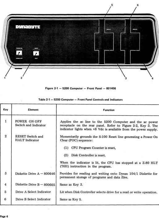
Figure 2-1 - 5200 Computer - Front Panel - 801406
Table 2-1 - 5200 Computer - Front Panel Controls and Indicators
Key Element Function
1 POWER ONOFF Applies the ac line to the 5200 Computer and the ac power Switch and Indicator receptacle on the rear panel. Refer to Figure 2-2, Key 3. The indicator lights when +8 V dc is available from the power supply. 2 RESET Switch and Momentarily grounds the S-100 Reset line generating a Power On
HAL T Indicator Clear (POC) sequence:
(1) CPU Program Counter is reset, (2) Disk Controller is reset.
When the indicator is lit, the CPU has stopped at a Z-80 HLT (76H) instruction in the program.
3 Diskette Drive A - 800646 Provides for reading and writing onto Dysan 104/1 Diskette for permanent storage of programs and data files.
4 Diskette Drive B - 800665 Same as Key 3.
5 Drive A Select Indicator Lit when Disk Controller selects drive for a read or write operation. 6 Drive B Select Indicator Same as Key 5.
[image:5.618.37.552.59.764.2]2. PHYSICAL DESCRIPTION
2.01 The 5200 Computer illustrated in Figure 1-1
is an integrated piece of electronic equip-ment incorporating all necessary component assemblies. The principle assemblies are:
(1) Power Supply Module,
(2) Central Processing Unit (CPU),
(3) S-100 Bus Card Cage and Motherboard, (4) Random Access Memory (RAM), (5) Disk Controller
(6) Dual Diskette Drives and Auxiliary Controller (AUX). Some of the optional assemblies are:
(7) Octaport (an eight-port serial I/O).
Details on these individual assemblies, as well as their schematic diagrams and replaceable parts lists, are furnished under separate cover as individual technical manuals. These assemblies have been enclosed in an exceptionally com pact package measuring 52 cm x 47 em x 18 cm (20.5 in. x 18.5 in. x 7 in.) weighing 25 kg (about 55 lbs.).
2.02 The 5200 draws nominally 313 VA of
115 Vac, 60 Hz commercial power. It may be factory optioned for operation from a 230 Vac, 50 Hz line.
2.03 The 5200 is designed to operate efficiently
in an environment with an ambient temper-ature range from 10°C to 35°C (50°F to 95°F) and with a relative humidity from 20 to 80 per cent.
2.04 Figures 2-1 through 2-3 provide number
key callouts of all components located on the front, rear and interior of the 5200. Associated Tables 2-1 through 2-3 provide a cross reference for each callout, identifying the respective part as to function, description and/or designation.
Front Panel
2.05 Refer to Figure 2-1 for the description
which follows. The 5200 Computer Front Panel has only two operating controls with which the user should be concerned.
(1) The POWER ON OFF Switch turns the computer on and off. The switch also connects the ac line power to a convenience receptacle on the rear panel for ppwering a mass storage device such as the Dynabyte 5010. The switch also contains an indicator which lights when there is an output from the internal +8 V dc power supply.
IMPORTANT
The 5200 Computer should never be turned on or off while a diskette is installed in a drive.
(2) The RESET Switch is used to restart the computer if it should become locked up due to a software or hardware malfunction. Operating the RESET Switch causes the S-100 Reset Line, Pin 75, to be active low. The Reset Line is an- input to the Power On Clear (POC) circuits and resets the CPU Program Counter, Disk Controller, etc. Then the CPU initiates a reboot by jumping to a starting address appropriate for the user's system. The switch also contains an indicator, which, when lit, indicates the CPU has read a Halt (HL T) instruction and has stopped.
The right half of the front panel contains the 5.25 inch dual diskette storage unit. The left drive is designated A and the right B. A red indicator above each drive door is lit when the drive is performing a read or write operation.
Rear Panel
2.06 Figure 2-2A and Figure 2-2B illustrate
400690
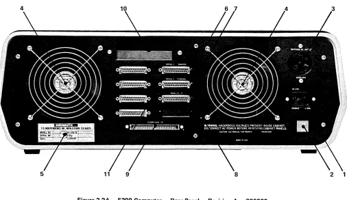
Figure 2-2A - 5200 Computer - Rear Panel - Revision A - 800266
Figure 2-2B - 5200 Computer - Rear Panel - Revision B - 802470
[image:7.612.35.558.67.690.2]Key
1
2
3
4
5
6
7
8
9
10
11
Table 2-2 - 5200 Computer - Rear Panel Controls and Connectors
Element
Ac Line ReceptacIe (J6)
Ac Line Fuse (F1)
SWITCHED AC OUTLET Receptacle (J7)
Axial Fan(s)
Dynabyte Identification Plate
SERIAL 1 PRINTER Port Receptacle
SERIAL 2 TERMINAL Port Receptacle
PARALLEL I/O Port Receptacle
FLOPPY DISK I/O Receptacle
Hard Disk I/O Access Hole and Clamp
I/O Port Connector Area
Function
IEC standard three-wire male receptacle. Provides for ac line, neutral and a third wire bonded to the chassis frame. Mates with Belden P-2392 ac cord set for U.S. domestic use or the appropriate cord set for the export country.
Provides ac line overcurrent protection: (1) 115 Vac - 6 A.
(2) 230 Vac - 3 A.
Early serial number units are provided with a circuit breaker in this position.
NEMA three-wire female receptacle provides for the ac line, neutral and third wire bonded to the chassis frame. This receptacle is switched by the POWER ON Switch on the front panel, refer to Figure 2-1, Key 1, and is protected by fuse, Key 2, above. This outlet normally supplies power to a 5010 Dual Diskette Storage Unit, 200 VA maximum ..
Provides for drawing heat from the power supply module and internal heat dissipating pc assemblies.
Furnishes the model and serial number necessary for warranty service. Refer to Figure 6-1.
DB-25-S connector. Optionally EIA RS-232C or 20 rnA current interface. Connection point for the EIA cable to the Serial Printer. DB-25-S connector. Optionally EIA RS-232C or 20 rnA current interface. Connection point for the EIA cable to the Video Terminal.
DB-25-S connector. Eight-bit parallel I/O connection point to 25-conductor cable to a parallel printer.
50-conductor ribbon connector. Provides a connection point for the cable to the Dynabyte 5010 Dual Diskette Storage for I/O data, control and status lines.
Furnishes a hole and clamp for the cable to the Dynabyte 5012 Cartridge Module Drive or 5011 or 5013 Winchester Drive.
Provides positions for DB-25-S connectors. Figure 2-2 illustrates' connectors for:
(1) Three ports from the CPU,
400690
CAUTION
Power consumption from the ac convenience receptacle is limited to 200 VA.
2.07 A four-inch fan(s) draws heat dissipated
internally out the rear panel. Air is drawn into the 5200 cabinet through louvers provided in the bottom of the cabinet. Refer to Figure 2-3.
IMPORTANT
Install the 5200 Computer so as not to obstruct the air flow through the louvers in the bottom of the cabinet and allow a three-inch clearance from the rear of the fan.
Desk-type system cabinets supplied from Dynabyte are designed to assure constant air flow through the computer.
2.08 Several mass storage devices can be used
with the 5200. The rear panel furnishes connector access for these devices.
(1) A fifty-pin ribbon cable connector provides for disk I/O signals, control signals and status signals to a Dynabyte 5010 Dual Diskette Storage Unit.
(2) A rectangular hole provides access for a multi-wire ribbon cable for disk I/O signals, control and status to a Dynabyte 5012 Cartridge Module Drive or Dynabyte 5011, 5013 or 5014 Winchester Drive.
2.09 Eight (sixteen) positions are provided on
the rear panel for DB-25-S connectors and are used for I/O signals to the system peripheral devices such as:
(1) Serial Printers, (2) Video Terminals, (3) Parallel I/O Printer,
(4) Acoustical Coupler or Modems, ( 5 ~ Plotting Terminals.
Page 8
Each installation will vary depending upon the selection of peripheral devices and the appli-cations programs in use. Three I/O ports are furnished as part of the CPU. These are shown connected to the rear panel illustrated in Figure 2-2 and 2-3. In applications requiring additional ports, a Quadraport or an Octaport may be installed into the S-100 Bus and interconnected to the rear panel. Both the front and rear panels are secured to their respective bezel by 6-32 Kep nuts. Each bezel is secured to the base plate by 6-32 screws. Both panel and bezel may be easily removed for servicing or installation of additional I/O ports in the field.
Card Cage - S-100 Bus
2.10 Refer to Figure 2-3 for the description
which follows. The card cage furnishes a rigid support structure for the S-100 Bus cards when they are inserted into the S·:100 Bus. The Motherboard PC Assembly contains 12 S-100 Bus receptacles or jacks, J1 through J12. Each jack has 100 separate pins. The actual bus consists of 100 parallel traces on the pc board connecting the same pin on each jack. Each line has a ground trace between it and the adjacent line to minimize coupling between signal lines.
2.11 The S-100 Bus lines are described by
function in Part 3 of this manual. Physically they make up five groups:
(1) Power and common lines. These are con-nected to the power supply module discussed in 2.17. Six lines.
(2) Address lines. 16 lines.
(3) Data In and Out lines. 16 lines. (4) Control Signal lines. 40 lines. (5) Dynabyte Reserved lines. 22 lines.
S-100 Bus Cards
2.12 Dynabyte S-100 Bus cards are pc assemblies
normally measuring 5 x 10 inches. A lOa-pin edge connector mates with the S-100 Bus connector on the motherboard. This connector is offset by 5/8 inch from the card centerline, i.e., an S-100 Bus card cannot be inserted into a jack backwards.
2.13 Dynabyte S-100 Bus cards may have one or
more on-board regulators for regulating and distributing the dc power supply voltages from the bus to the logical elements on the card.
NOTE
An S-J 00 Bus card should never be inserted or removed from the bus when the ac line
power is on.
2.14 A solder mask is applied to the component
and non-component sides of the pc boards when it is manufactured and before it is loaded with components. This mask covers all surfaces except:
(1) The 100 gold-plated fingers of the edge connectors,
(2) Each of the plated-through holes.
The solder mask assures there will be no bridges between traces. The soldering operation can then only take place at a hole where normally solder joins a component lead and a pad.
2.15 Dynabyte S-100 Bus cards usually provide
sockets for most multi-lead active devices to facilitate fault location and servicing.
2.16 Options for Dynabyte S-100 cards are
provided by three methods:
(1) Dual-In-Line packaged (DIP) switches of one to nine poles, SPST, are normally used in functions which may have to be set to the user's individual installation.
(2) Bare wire straps are soldered into the pc board for options which are installed at the factory. These are not to be changed in the field except by instructions from Dynabyte Customer
Support or when specified in the individual Dynabyte S-100 Bus Card Technical Manual.
IMPORTANT
Never change the settings of an Option Switch without referring to the Option Switch Tables in the individual Dynabyte S-J 00 Bus Card
Technical Manual.
(3) Instructions are written into a program-mable read-only memory (PROM) at the Dynabyte factory resulting in a read-only mem-ory (ROM). In some applications a ROM can be
phantomed into a desired range of addressed
RAM. Phantoming means a memory segment can replace another under program control. When the 5200 is set to POWER ON or RESET is operated, the CPU jumps to the starting address of the disk controller ROM. The ROM boot instructions are overlaid at the common address location. These instructions are for the CPU to read Track 0, Sector 1 from Drive A. This particular operation is called the ROM Boot. Track 0, Sector 1 contains additional instructions which are loaded into RAM and executed. These instructions cause the CPU to read the Dynabyte Disk Operating System from the diskette or disk. This second operation is called the Disk Boot. The ROM is then switched out.
NOTE
Dynabyte ROMs are individually marked with a Dynabyte part number. The part number represen ts an individual program for a specific
equipment configuration. The ROM part
numbers are tabulated for various equipment configurations in the specific S-J 00 Bus Card
Technical Manual.
Changes in options of this type are made by exchanging the particular ROM. ROMs are only available from Dynabyte.
2.17 Dynabyte S-100 Bus cards carry a
400690
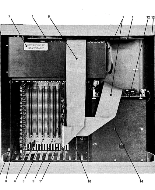
[image:11.620.47.556.71.695.2]5 8 4 3 9 11 10 14
Figure 2-3 - 5200 Computer - Interior
Key
1
2
3
4
5
6
7
8
9
10
11
12
Table 2-3 - 5200 Computer - Interior Major Assemblies
Element
Axial Fan(s)
Power Supply Module 800361
Card Cage and S-100 Bus PC Assembly 800038 Front Panel Indicator Connector J13
Front Panel Power Connector
CPU I/O Cable 800285
Disk Interface I/O Cable 800228
Random Access Memory PC Assembly 800589 CPU PC Assembly 803439
Disk Controller PC Assembly 800741 Cabinet Louvers Auxiliary Controller 800703
Function
Provides forced air cooling to the power supply module and internal heat dissipating pc assemblies.
Accepts 115 or 230 Vac, 50-60 Hz and supplies the following pre regulated voltages to the S-100 Bus and other assemblies:
(1) +16 Vdc, (2) +12 Vdc, (3) + 8 Vdc, (4) + 5 Vdc,
(5) Power Supply common, (6) -16 Vdc.
Provides 12 pc assembly positions. Power and signal busses are tabulated by function in Table 7-1.
A four-position connector which provides a connection point for the cable to the POWER ON, HALT indicators and the RESET switch on the front panel.
A two-position connector which provides a connection point for the cable to the POWER ON switch on the front panel.
Provides for the interconnection of data, status and control between the CPU PC Assembly and the rear panel I/O ports. Refer to Figure 2-2, Key 6, 7 and 8.
Provides for the interconnection of data, status and control between the Controller PC Assembly and the Rear Panel Disk I/O receptacle. Refer to Figure 2-2, Key 9.
Provides storage for the Operating System, Application Program and variables during program execution.
Provides a central processor, interrupt logic, two serial I/O ports and one parallel I/O port.
Provides the logic, status registers and ROM bootstrap to support the Dynabyte diskette drives.
Provides air inlets for drawing air into the cabinet for ventilation. Provides the specialized electrical functions for:
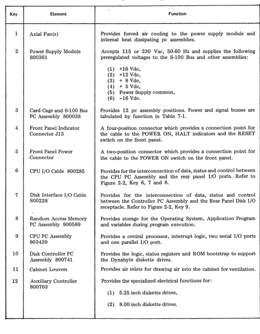
[image:12.618.48.579.72.754.2]400690
Table 2-3 - 5200 Computer - Interior Major Assemblies (Continued)
Key Element Function
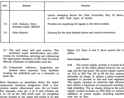
option strapping allows the Disk Controller, Key 10 above, to work with both types of media.
13 5.25 Diskette Drive Interface Cable 800437
Provides for supplying I/O signals to the drive module.
14 Drive Module Housing for the dual diskette drives and control electronics.
(1) The card name and part number. This facilitates board identification and refer-encing for reordering, servicing and referrefer-encing the appropriate Dynabyte S-100 Card Technical Manual, schematic or replaceable parts list. (2) Component reference designators are
marked when practical. They facilitate locating the individual part on a schematic or parts list.
Most Dynabyte pc assemblies derive the major component reference designators from a row-column matrix silkscreened onto the pc board. For example, rows are A to D and columns are 1 to 18 on the 64K RAM card. An integrated circuit located in the upper left comer is A1 and the one located in the lower right comer is D18.
2.18 Input/Output (I/O) Signals not affecting the S-100 Bus are transferred over special multi-pin connectors normally located at the top of the pc assembly. Cable harnesses which mate with these connectors are normally made up of flat multi-pair or flat twisted multi-pair cable.
Page 12
Figure 2-3, Keys 6 and 7, show typical flat I/O cables.
Power Supply Module
2.19 The power supply module is located at the rear of the 5200 cabinet between the card cage and the rear panel. The power supply operates on 115 or 230 Vac, 50 or 60 Hz line, optioned internally by straps. It utilizes a phase-controlled regulator to provide ac line and load regulation. The supply operates at relatively high efficiency and utilizes a minimum of components resulting in high reliability. The ac chassis wiring to the power supply module includes an EMI filter to minimize radiation of power supply switching transients over the ac line.
Dual Diskette Drives
[image:13.624.35.554.76.487.2]3. FUNCTIONAL DESCRIPTION
3.01 Part 3 will furnish the user with an
overview of the 5200 Computer and the S-100 Bus. Detailed information on individual Dynabyte 8-100 cards is provided in its technical manual.
NOTE
An
*
sUffix to a signal name indicateslogical NOT and active low.
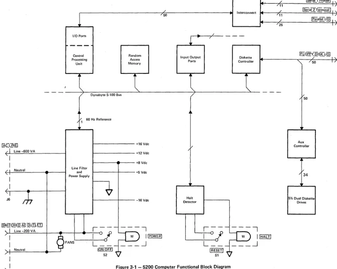
3.02 Figure 3-1 illustrates the 5200 Computer
in block diagram. It should be used in conjunction with the schematic diagrams in Part 7 to familiarize the user with the circuits. The 5200 Computer chassis can be divided into four logical sections:
(1) Operational Controls, (2) Power Supply Module, (3) S-100 Bus,
(4) Dual 5.25 inch Dual Diskette Drives.
3.03 Two operation controls are provided on
the 5200 Computer.
(1) The POWER switch applies ac line voltage to the fans, ac convenience receptacle and power supply module. The POWER ON indicator is lit when the power supply module outputs nominally +8 Vdc.
(2) The RESET switch pulls the Reset line, Pin 75, of the S-100 Bus low to initiate a restart of the CPU, etc. The reset switch housing contains a lamp and indicates a halt when lit. A Halt Detector is part of the S-100 Motherboard PC Assembly. This detector moni-tors the HLTA line, Pin 48. When this status line goes high, a HLT instruction has been executed. The HALT indicator is lit.
3.04 The Power Supply Module converts ac line
voltage to low dc voltages for the S-100 Bus and monitoring circuits. "It provides regulation against ac line fluctuations and load variations of the S-100 Bus. The output voltages are nominally:
(1) +16 Vdc, (2) +12 Vdc, (3) +8 Vdc, (4) +5 Vdc, (5) -16 Vdc.
One adjustment, R2 on the Modulator PC Assem-bly and part of the power supply module, is used to set the +8 V dc supply output voltage. The other voltages are nominal and track the +8 V dc. Refer to Figure 6-2 for the tolerance range.
3.05 Regulation is provided by a triac modulating
the ac line applied to the low voltage power transformer. The +8 Vdc output line is monitored and a feedback loop is used to control the con-duction of the triac resulting in phase-controlled regulation.
3.06 The +16, +8 and -16 output voltages are
passively filtered. Ripple on the +8 V dc line is 0.3 to 1 Volt. The +5 and +12 voltages are set and controlled by three-terminal regulators. These two voltages power the dual diskette drives.
3.07 The S-J 00 Bus system consists of a set
of signal lines used to carryall information, interface messages and device-dependent messages among interconnected devices.
3.08 The bus structure is organized into seven
sets of signal lines: (1) Data Lines,
(2) Address Lines, (3) Status Bus, (4) Control Output, (5) Control Input Bus, (6) Vectored Interrupt Bus, (7) Utility Bus.
I/O Ports
""----Central Processing Unit Random Access Memory
+
/ /50 ~ Interconnect .....
/ L - - _ _ _....
Input Output Diskette
Ports Controller
•
.-___
'--_'~~~~---~~--~----~---~-
/ Dynabyte S-100 Bus'"
/"-~CLThI]]
/ 1 Line -600 VA
"I
1 / I Neutral
"I
J6
~~
/ 60 Hz Reference / 1
,p
Line Filter and Power Supply
1---
+16 Vdct - - - -+12 Vdc
t - - - A - - - -+8 Vdc
~----~---+5Vdc
1---4----
-16 VdcI[w.TICHE~ g: QUTLITI
1 Line-200VA - , - - - ,
r
>-'
,
1-'-
~=
==
='-'~=
_"-_:..:...:..._ -_
----<+
..
-_
-_~¢
...
F-A-NS-l---!...I--("\-OL _ _ _ _ _
IP--;-
I
[powTR]~
1 Neutral ION OFFJ
/ 1 ~
I
...
/ /..
Halt Detector 1D
Figure 3-' - 5200 Computer Functional Block Diagram.,.. /
/11
~ /
, /11
~ / , /25 ~ '"
-~ial1 Prin~ 1 ,
1 /
~aITTerm~ 1 ,
1 /
~aiiell@ I ,
17
lIToppy DISK I@ / I ,
'"
·/50/
/ 50
..
,
Aux Controller
/
/ 34
[image:15.798.64.722.25.549.2]NOTE
In and Out References are in respect to the CPU.
3.09 The data bus consists of 16 lines grouped as two unidirectional 8-bit busses for byte operations.
(1) Data output appears on the data output
bus DOD - D07. D07 is the most
signifi-cant bit.
(2) Data input appears on the data input bus DID - DI7. DI7 is the most significant bit.
3.10 The address bus consists of 16 signal lines used to select a specific location in memory or a specific input/output device for communi-cations during the current bus cycle. The memory address bus consists of 16 lines specifying 1 of 64K memory locations. These 16 lines are named
AD through A15, where A15 is the most significant bit. The I/O device address bus consists of lines,
AD through A 7, specifying 1 of 256 I/O devices, with A 7 used as the most significant bit. Address lines A15 - A8 are used as an I/O address modifier in specific cases, i.e., the Octaport.
3.11 The status bus consists of nine lines that identify the nature of the bus cycle in progress and qualify the nature of the address on the address bus. The mnemonics for status lines always begin with a lower case s and consist of:
(1) Memory Read - sMEMR (2) Op-Code Fetch - sM1
(3) Input -sINP (4) Output - sOUT (5) Write Cycle - sWO*
(6) Interrupt Acknowledge - sINT A (7) Halt Acknowledge - sHLT A (8) Memory Request - sMREQ*
(9) Memory Refresh - sRFSH *
3.12 The lines of the control output bus deter-mine the timing and movement of data during any bus cycle. The mnemonics for the control output lines always begin with' a lower case p. The four lines are:
(1) pSYNC*, which indicates the start of a new bus cycle.
(2) pDBIN, a generalized read strobe that gates data from an addressed slave onto the data bus.
(3) pWR*, a generalized write strobe that writes data from the data bus into an addressed slave.
(4) pHLDA, the hold acknowledge signal that indicates to the highest priority temporary master that the permanent master is relinquishing control of the bus.
3.13 The five lines of the control input bus allow bus slaves to synchronize the opera-tions of bus masters with condiopera-tions internal to the bus slave, e.g., data not ready, and to request operations of the permanent master, e.g., interrupt or hold. The five control input lines are:
(1) RDY (2) XRDY (3) INT* (4) NMI* (5) HOLD*
The ready lines are used by bus slaves to synchro-nize bus masters to the response speed of the slave. Thus cycles are suspended and wait states inserted until both ready lines are asserted. The RDY line is the general ready line for bus slaves. It is specified as an open collector line. The XRDY line is a special ready line used by test devices to stop and single-step bus masters. It is not specified as an open collector line and should not be used by other bus slaves since a bus conflict may exist.
400690
generation. If the bus master accepts the interrupt request on the INT* line, it may respond with an interrupt acknowledge bus cycle accepting vectoring information from the data bus.
3.15 The NMI* line is a nonmaskable interrupt
request line, that is, it may not be masked off by the bus master. Accepting an interrupt on the NMI* line will not generate an interrupt acknowledge bus cycle. An interrupt request on the INT* line is asserted as a level, that is, the line is asserted until interrupt service is received. An interrupt request on the NMI* line, on the other hand, is asserted as a negative-going edge, since no interrupt acknowledge cycle will be generated. Both lines are specified as open-collector lines.
3.16 The hold request line, HOLD*, is used by
temporary bus masters to request control of the bus from the permanent bus master to prevent temporary masters from gaining bus con-trol. The HOLD* line is specified as an open collector line and may only be asserted at certain times.
3.17 The eight lines of the vectored interrupt
bus are used in conjunction with the . generalized vectored interrupt request, INT*, to arbitrate among eight levels of interrupt request priorities. The eight lines of the vectored interrupt bus are VIO* through VI7*, where VIO* is considered the highest priority interrupt. The vectored interrupt lines should be implemented as levels; that is, they should be held active until service is received.
3.18 Power in the Dynabyte S-100 Bus systems
is distributed to bus devices as unregulated voltages. A total of six bus lines are used:
(1) +8 Volts, 2 lines, (2) +16 Volts, 1 line, (3) -16 Volts, 1 line,
(4) Power supply common, 2 lines.
Page 16
3.19 The system clock, 4 MHZ PHASE 2,
is generated by the CPU. The control timing for all bus cycles must be derived from this clock. This signal is never transferred during a bus exchange operation.
3.20 Another line, called CLOCK, is specified
as a 2 MHz, 0.5 percent tolerance, signal with no relationship to any other bus signal. It is used by counters, timers, baud-rate generators, etc.
3.21 System reset functions are divided into
two lines:
(1) RESET*, is an open collector input line that requests a Power On Clear (POC). (2) POC*, power on clear is active on power on and when requested by RESET*, is specified as having a minimum active period of 10 ms.
3.22 The memory write strobe, MWR T, is
gener-ated by the permanent bus master and is defined as:
MWRT
=
pWR • sOUT* (logic equation)3.23 Another line, PHANTOM*, is provided for
overlaying bus slaves at a common address location. When this line is activated, phantom bus slaves are enabled and normal bus slaves are disabled. This line is specified as an open-collector line.
3.24 The remaInIng lines are designated as
Dynabyte reserved and for use in future S-100 card and system designs.
3.25 The Dual Diskette Drives provide the 5200
4. SPECI FICATIONS (2) The specific Dynabyte S-100 cards installed in the bus, i.e., the hardware.
4.01 Part 4 furnishes the user with information for shipping and installation and should be used to establish acceptance tests if they are performed. Minor deviations from the specifications tabulated in Tables 4-1 and 4-2 which do not affect the 5200 Computer are excluded from the Dynabyte Warranty.
4.03 Table 4-1 summarizes the 5200 Computer Functional Specifications with the following hardware:
(1) Central Processing Unit, (2) 64K Random Access Memory.
4.02 The functional specifications of the 5200
Computer are determined by: For other hardware configurations the user should refer to the individual Dynabyte S-100 Card Technical Manual Specifications.
(1) The Dynabyte Disk Operating System and the particular application program running, i.e., the software.
Table 4-1 - 5200 Computer Functional Specifications
Parameter Characteristics
Front Panel Section
Power Switch Alternate action. Lit in POWER ON condition.
Reset Switch Momentary action. Lit when the CPU is in the Halt condition. Card Cage Section
System Dynabyte S-100 Bus
Capacity 12 positions
EMI Fully shielded backplane
Processor Section
Type Z-80A
Clock Rate 4 MHz
Instruction Set 158
Interval Timer
Number 10
Time Unit 64 J1S per count
Range 1 to 255 units (64 J1S -16.32 ms)
Interrupt Interrupts on 0 count under program control Real Time Clock
Frequency Ac line synchronous
400690
Table 4-1 - 5200 Computer Functional Specifications (Continued)
Parameter Characteristics
Interrupts
Number 16
Priority, Highest Timer 6
Timer 7 Port Interrupt Timer 8
Serial 2 Receive Data Available Serial 2 Transmit Data Available Timer 9
Timer 10 or Parallel Port Input Bit 7 Timer 1
Timer 2
Real Time Clock Timer 3
Serial 1 Receive Data Available Serial 1 Transmit Buffer Empty Timer 4
Priority, Lowest Timer 5
Levels of Interrupt 2
Masking
Levell Masks all in terru pts
Level 2 Individual masking of interrupts Off Card In terru pts One maskable
One unmaskable Input/Output Section
Serial Ports 2
Rates 110, 150, 300, 880, 1200, 2400, 4800, 9600, 19,200, 38,400, 76,800 baud
Rate Selection Software control
Connector DB-25-S
Data In EIA RS-232C
Data Out EIA RS-232C
Signal Common EIA RS-232C
Data In 20 rna current loop
Data Out 20 rna current loop
Parallel Port 1
Input 8 bits
Input Ready Flag Edge triggered
Input Sense 1 bit
Output 8 bits
Output Strobe 1 bit
Output Flags 2
Connector DB-25-S
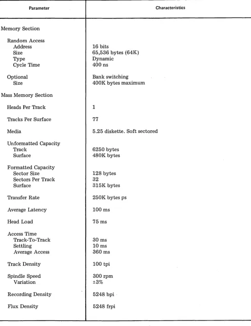
[image:19.612.41.547.89.728.2]Table 4-1 - 5200 Computer Functional Specifications (Continued)
Parameter Characteristics
Memory Section Random Access
Address 16 bits
Size 65,536 bytes (64K)
Type Dynamic
Cycle Time 400 ns
Optional Bank switching
Size 400K bytes maximum
Mass Memory Section
Heads Per Track 1
Tracks Per Surface 77
Media 5.25 diskette. Soft sectored
Unformatted Capacity
Track 6250 bytes
Surface 480K bytes
Formatted Capacity
Sector Size 128 bytes
Sectors Per Track 32
Surface 315K bytes
Transfer Rate 250K bytes ps
Average Latency 100 ms
Head Load 75ms
Access Time
Track-To-Track 30 ms
Settling 10ms
Average Access 360ms
Track Density 100 tpi
Spindle Speed 300 rpm
Variation ±3%
Recording Density 5248 bpi·
[image:20.613.76.571.86.729.2]400690
Table 4-' - 5200 Computer Functional Specifications (Continued)
Parameter
Mass Memory Section (Continued) Encoding Method
Reliability (estimated) MTBF
PM MTTR Error Rate
Soft Read Errors Hard Read Errors Seek Error Media Life
Passes per track Insertions Power Supply Section
Type Voltages
Adjustment Rear Panel Section
DB-25-S Connector Positions Diskette Storage Connector Convenience Receptacle
Page 20
MFM
8500 hours None 30 minutes
Less than 1 x 109 bits
Less than 1 x 1012 bits
Less than 1 x 10⁶ seeks
Greater than 3 x 10⁶
Greater than 30,000
Phase-con trolled regulator ±16 Vdc at 6 A
+8 Vdc at 20 A
Characteristics
+12 Vdc at 1.0 A, 1.3 A peak +5 Vdc at 0.5 A
1
8 or 16
50 conductor ribbon
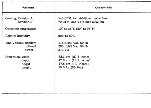
Table 4-2 - 5200 Computer Physical Specifications
Parameter Characteristics
Cooling, Revision A 140 CFM, two 4-5/8 inch axial fans Revision B 70 CFM, one 4-5/8 inch axial fan Operating temperature 10° to 35°C (50° to 95°F)
Relative humidity 20% to 80%
Line Voltage, standard 115 ±10% Vac, 60 Hz
optional 230 ±10% Vac, 50 Hz
power 313 VA
Dimension, width 52.1 cm (20.5 inches)
depth 47.0 cm (18.5 inches)
height 17.8 cm (7.0 inches)
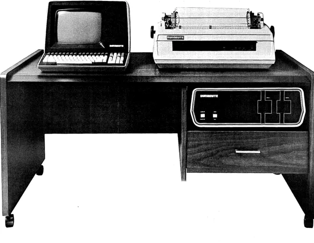
Figure 5-' - 5200 Computer Installed In Dynabyte Desk Enclosure
~
o o
C»
(C
5. OPERATION AND INSTALLATION
Unpacking
5.01 After the 5200 Computer arrives, the shipping cartons should be examined for visible loss or damage.
IMPORTANT
Each ullit's shippillg cartoll should be retained for the warrallty period alld used for the returll of equipment to Dynabyte if it is
Il ece ssar y.
Since the 5200 can be ordered in several optional configurations:
(1) Random access memory size, (2) RAM bank switching,
(3) Number of I/O ports, (4) Type of mass storage, (5) Slave CPUs,
check to make certain the packing slip agrees with the Purchase Order. Do not apply power to any unit.
5.02 Next, check each unit for concealed loss, damage or omissions in shipment. The laminated wood cover is secured to the chassis
by six 3/32 hex head 6-32 x 1/2 screws. A hex head wrench is supplied with the 5200 Computer.
IMPORTANT
Remove only the three center hex head screws from each side of the cover.
Figure 2-3 illustrates the 5200 interior. The Dynabyte S-100 Bus structure allows any Dynabyte S-100 card to be installed into any vacant card position, but as a matter of practical cabling convenience, the order shown in Figure 2-3 is recommended.
Step Procedure
1
2
3
If a Dynabyte mass storage, e.g., 5010' or 5012 was ordered, install the Controller PC Assembly and connect its Disk Interface I/O Cable to the rear panel.
If additional I/O Ports were optioned, confirm that the Octaport PC Assembly is installed and its Port I/O Cable is connected to the rear panel.
Check the interior for loss or damage during shipment:
(1) Loose screws, nuts or washers, (2) Broken wires or loose
components,
(3) Major assemblies broken at mountings.
IMPORTANT
The equipment is thoroughly tested, inspected and carefully packed before leaving the Dynabyte factory. Claims for loss or damage should be made upon the carrier, NOT TO Dynabyte, as follows:
(1) Visible Loss or Damage - must be noted on the freight bill or express delivery sheet. The form required to file such a claim will be supplied by the carrier.
(2) Concealed Loss or Damage - means loss or dam age which does not becom e apparent until the equipment has been unpacked and placed in service. When the damage is discovered upon unpacking, make a written request for an inspection by the carrier's agent within fifteen days of the delivery date. Then file a claim with the carrier.
[image:24.617.331.575.70.666.2]400690
Ac Line
5.03 The 5200 Computer is normally wired and shipped from the factory for operation from a 115 Vac, 60 Hz single ac line. The ac line receptacle, J6, is provided with a third wire bonded to the chassis.
IMPORTANT
Safe operation of Dynabyte equipment
depends upon the user providing a two-wire,
grounded, 115 Vac, 15 Amp service wall
receptacle.
Select a wall receptacle which is not switched except for a circuit breaker. Ideally no other equipment should be connected to the branch circuit.
NOTE
The 5200 Computer chassis is wired at the
factory for either 115 Vac, 60 Hz or 230 Vac,
50 Hz operation. Conversion in the field for operation on the alternate voltage is not
recommended.
Options
5.04 The user should refer to the Dynabyte S-100 Card Technical Manual for detailed information for options to individual S-100 cards and system components. Figures 5-2 through 5-5 will furnish the 5200 user with option settings necessary for a 5200 system to run diagnostic programs.
5200/5010 Units
5.05 The following procedure will serve as an option check list when a 5200 Computer Unit stands alone or is used with or expanded to include one 5010 Unit.
Page 24
Step
1
2
3
4
Procedure
For a stand-alone 5200 Computer Unit installation, check the Main Disk Controller PC Assembly options:
(1) Disk Clock Strap Option to DB8/4 8/2 position,
(2) A ROM should be installed appropriate to drive manu-facturer and number of surfaces. Refer to Figure 5-4.
If a system does not include a 5010 Unit, check the Auxiliary Disk Con-troller options in the 5200 Computer Unit:
(1) Address Strap Option to 0, (2) Terminating Resistor Pack at
A3.
Refer to Figure 5-5.
If the system does include a 5010 Unit, check the Auxiliary Disk Controller PC Assembly options in the 5200 Computer Unit.
(1) Address Strap Option to O. (2) No Terminating Resistor Pack
at A3.
Check the Auxiliary Disk Controller PC Assembly options in the 5010 Unit: (1) Address Strap Option to 1, (2) Terminating Resistor Pack at
IMPORTANT
Only one Terminating Resistor Pack should be installed in a Disk Storage System. The Resistor Pack should only be installed
in the last Auxiliary Controller in the Disk Storage System.
Set Up and Turn On
5.06 The following procedure will serve as a useful check list for setting up or resetting up the 5200 Computer. For illustration purposes the system components are:
(1) 5200 Computer, 64K Dynamic RAM. (2) Serial 1 Port is connected to the Serial
Printer, 300 baud, and is the listing device (LST:).
(3) Serial 2 Port is connected to the Video Terminal, 9600 baud, anc;l is the console device (CON:).
( 4) Dynabyte Disk Operating System Diskette.
NOTE
Set all ac line power switches to OFF.
Step Procedure
1 Install the 5200 so as not to obstruct the air flow through the louvers in the bottom of the cabinets. Make certain there is a thr~e-inch clearance from the rear of the fans. Dynabyte desk-type cabinets, Figure 5-1, are designed to assure constant air flow through the equipment cabinets.
2 Check the option switch settings: (1) Each S-100 Bus card. Refer to
5.04 above.
Step Procedure
(2) Video Terminal. Refer to the Technical Manual.
(3) Serial Printer. Refer to the Technical Manual.
3 Connect to computer system cables:
4
(1) EIA cable between Port 1 and the Serial Printer.
(2) EIA cable between Port 2 and the Video Terminal.
IMPORTANT
Tighten the retaining screws on the DB-25-S connectors.
Do not overtighten.
Connect the ac line cords:
(1) Video Terminal ac line cord to the wall receptacle.
(2) Serial Printer ac line cord to the wall receptacle.
(3) 5200 ac line cord to the wall receptacle.
5 Open both diskette drive doors.
NOTE
Always check the drive does not have a diskette installed before installing a diskette into a drive.
6 Turn on the ac power switches: (1) Video Terminal.
400690
Step Procedure
7 Verify the following:
(1) Power on indicators on all units are lit.
(2) Fan(s) in the 5200 are running. (3) Disk Drive A select lamp is
flashing.
8 Insert the System Diskette into Drive A and close the door.
9 The Video Terminal should present the Dynabyte sign-on message. 10 Refer to the 5200 Computer Operation
Mariual.
NOTE: The dots on the switches indicate the direction in which the switch should be set for correct operation.
Figure 5-3 - 64K Random Access Memory - Option Switch Settings
,J:::.
o o
0') (0
Serial Number Option Strap
NOTE: The dots on the switches indicate the direction in which the switch should be set for correct operation.
ROM Option Selection
. Dynabyte Part Number Mnemonic Dynabyte Equipment
Terminating
[image:31.797.96.686.36.514.2]Serial Number Resistor Pack Address Option Strap R4 R3
6. MAINTENANCE
6.01 The 5200 Computer is a result of several years of design, development and modern electronic manufacturing. The units are designed around the latest semiconductors and integrated circuits. They operate at relatively low power levels with adequate cooling. Each 5200 Computer is operated under power and functionally tested in the Dynabyte factory for a minimum of 72 hours before shipment. The 5200 Computer can be expected to operate at peak performance for long intervals. No routine maintenance is required except occasional dusting and cleaning of the painted surfaces with a good all-purpose cleaner which does not attack or scratch painted surfaces or plastic.
(1) Formula 409 All Purpose CI~aner Distributed by Clorox Company Oakland, Ca. 94612
available from most supermarkets is well suited for this application.
Customer Support Service
6.02 Maintenance and procedures described in this manual should be performed in accor-dance with local instructions and the individual user's maintenance plan. Maintenance and repair of the 5200 Computer during the warranty period should be limited to:
Step
(1) returning the 5200 Computer,
(2) isolation of a fault to a specific pc assembly or unit,
(3) replacement of the ac line fuse once.
NOTE
Dynabyte Authorized Service Centers (ASC) are staffed with factory-trained technicians that are supplied with technical manuals and rou tin ely receive service bulletins and
design change information on Dynabyte
equipment.
Repacking and Returning Material
6.03 The Dynabyte Customer Support staff is available by telephone for assistance in troubleshooting and recommendations for repairs.
If equipment is to be returned for repair or replacement, the following procedure will expedite repair and return of the equipment. All communi-cations and material should be directed to:
Procedure
Dynabyte, Inc. Customer Support 115 Independence Drive Menlo Park, Ca. 94025
(415) 329·8021
TWX 9103732019
1 Call Dynabyte Customer Support by telephone and provide the following information: (1) The nearest Dynabyte Authorized Service Center name and number if known.
(2) The Dynabyte Model Number and Serial Number of the equipment. Figure 6-1 illustrates the Dynabyte Identification Plate for equipment. Normally this is located at the rear of the equipment.
2 If the fault has been traced to a specific subassembly, e.g., an S-100 Bus card, furnish the type, part number and serial number. This information is marked on the component side of the pc assembly.
400690
Step Procedure
3 Furnish a brief statement of the problem.
4 Customer Support will issue a Return Material Authorization Number (RMA Number).
(1) The RMA permits the Dynabyte Customer Support staff to provide better coordination of returned material.
(2) The RMA permits the Dynabyte customer to easily reference material returned to Dynabyte.
NOTE
Material returned to Dynabyte without a Return Material Au thorization for repair will be refused by Dynabyte and returned to
the sender.
5 Package equipment in the Dynabyte packing carton in which the equipment was received.
If the original packing material is not available, Dynabyte Customer Support will provide information and recommendations or material to be used.
6 Fill out and enclose a Dynabyte Repair Service Report with the equipment or provide the following information in writing:
(1) The RMA number furnished by Dynabyte. (2) The nearest Dynabyte Authorized Service Center.
(3) Model number and serial number of equipment. Refer to Step 1 above. (4) A brief statement of the problem.
7 Ship the equipment to Dynabyte, shipment prepaid.
1 ( . 115 INDEPENDENCE DR .. MENl.O PARK, CA 94{)25 , I ,
P
Ii
f, j if Iii
4.
1
,""MODEL NO. Ae VOLTS 7f
2
--+SERIAL NO. FREO.S
3--+
DATE CURRENTKey Function
1 Dynabyte Model Number. 2 Dynabyte Chassis Serial Number. 3 Dynabyte date of manufacture. 4 Ac line voltage which the chassis
is wired for operation.
5 Ac line frequency which the chassis will operate.
[image:34.615.52.304.65.380.2]6 Power dissipation of chassis.
Figure 6-1 - Dynabyte Identification Plate
Diagnostics
6.04 A diagnostic program supplied on a diskette is available for the 5200 Computer from a Dynabyte Authorized Service Center. This program is a three-minute process to verify the 5200 works in general and the diskette drives are functioning properly. The program diskette is supplied with a Dynabyte Technical Manual describing the program operation in detail.
Fault Location
6.05 A troubleshooting chart has been included in this manual to assist the user in isolating a fault location to one of three areas. Refer to Table 6-1.
(1) The fault symptom resulted from incorrect user operation of the 5200 Computer.
(2) The fault symptom resulted from some other piece of equipment, e.g., cable, disk-ette storage, diskdisk-ette or terminal.
(3) The fault symptom resulted from a 5200 S-100 card or power supply module.
Table 6-1 does not tabulate all the possible symptoms, only those Dynabyte Customer Support has found most likely to occur. The diagnostic program, refer to 6.04 above, will also provide pointers for troubleshooting hardware mal-functions.
Power Supply Module Voltages and Adjustment
6.06 The procedure which follows will assist the user in checking and adjusting the power supply should it be necessary. The user will need a digital multimeter (DMM), e.g., Fluke 8020A or equal. Refer to Figure 6-2.
GND GND -IBV +8V +5V +16V +12V
Terminal Voltage Tolerance
Ac Line 115 Vac ±10%
6 +16 Vdc 17 +3/-2 Vdc 7 +12 Vdc 12 +3/-2 Vdc 4 + 8 Vdc 9 ±0.5 Vdc 5 + 5 Vdc 5 ±0.25 Vdc
1 OVdc PS Common
Reference
[image:34.615.328.570.340.689.2]3 -16 Vdc -17 -3/+2 Vdc
400690
Step Procedure
1 Remove the top cover. Refer to 6.08 below.
2 Remove the power supply cover. Refer to 6.09, Steps 1 through 3. 3 The power supply voltages are distributed from barrier strip, BSl.
4 Connect the DMM (-) lead to Terminal 1 and the (+) lead to Terminal 4. The voltage should be:
\9 ± 0.5 Vdc
I
5 . If it is necessary to adjust the +8 Vdc supply to bring this into tolerance, adjust R2 on the Modulator PC Assembly.
6 Check each of the other voltages tabulated in Figure 6-2 are in tolerance.
Removing Assemblies
6.07 The user will need the following hand tools to remove the major assemblies from the 5200 Computer chassis:
(1) 3/32 hex Allen wrench, (2) 11/32 socket wrench,
Step
(3) 1/4 socket wrench,
(4) No.2 Phillips head screwdriver, (5) No.3 Phillips head screwdriver.
6.08 Top Co ver - The descriptions which follow
. view the 5200 Computer from the front. Perform the following:
Procedure
WARNING
Hazardous voltages are present inside the cabinet. Disconnect ac power before removing
the cabinet cover or assem bUes.
1 Remove the center three 3/32 hex head screws from each side of the top cover.
2 Remove the cover and place it in position so the woodgrain surf~ce will not be marred during servicing.
6.09 Power Supply Module - is located between the card cage and the rear panel. Perform the following:
Step Procedure
NOTE
Halldle I/O cables with care as they call be easily damaged.
1 Disconnect the following cables: (1) Port I/O Cable from the CPU.
(2) Disk Interface I/O Cable from the Controller. Dress cables back over the rear panel.
2 Remove the two 6-32 Kep nuts and flat washers from the left side of the black anodized power supply cover.
3 Remove the two 4-40 Kep nuts and flat washers from the right side of the power supply cover. 4 Remove the power supply cover.
5 Disconnect the Motherboard Power Cable. (1) BS1 - 1 BLK (2)
- 2 BLK (2) - 3 VIO/WHT (1) - 4 ORG/WHT (2) - 5 ORG (3) - 6 RED/WHT (1) - 7 RED (2) (2) BS2 - 5 YEL (1)
6 Remove the four Phillips head 10-32 screws, star washers and flat washer which secure the Power Supply Module to the cabinet base.
7 Shift the Power Supply Module slightly to gain access to the rear interior. Disconnect the ac line. This is two push-on connectors on the EMI line filter.
400690
6.10 Card Cage - S-JOO Bus Motherboard - is located directly behind the front panel. The Motherboard Power Cable must be discon-nected first. Repeat 6.09, Steps 1 through 5. Then, perform the following:
Step Procedure
1 Remove all the S-100 cards installed in the card cage.
2 Disconnect the front panel cable connector from J14, the four-conductor pc-mounted receptacle. 3 Remove the fourteen 6-32 x 3/8 Phillips head screws and star washers which secure the S-100
Motherboard PC Assembly to the cabinet base. 4 Remove the card cage from the 5200 Computer.
5 Remove the eight 6-32 x 3/8 Phillips head screws and star washers which secure the S-100 Bus Motherboard PC Assembly to the card cage.
6.11 Front or Rear Panel - Both panels are secured to the respective cabinet bezel by five 6-32 Kep nuts. It is more convenient to remove the entire bezel. Perform the following:
Step Procedure
1 Remove the two 3/32 hex head screws from each side.
2 Remove the five 8-32 x 3/4 Phillips head screws and star washers which secure the bezel to the cabinet base. Two of these screws also secure rubber bumpers.
3 Disconnect the electrical connections from the respective panel.
(1) Front Panel - Disconnect the ac line cable from the rear panel and the front panel cable connector from J14, the four-conductor pc mounted receptacle.
(2) Rear Panel - Disconnect the ac line cable to the front panel and the ac line cable to the power supply. This consists of two push-on connectors on the EMI line filter.
4 Remove the panel.
6.12 Dual Diskette Drive Module - is located behind the front panel. Prior to August 1, 1979, this module utilized a different method of mounting, Revision A, than the current production units which use Revision B method of mounting. Perform the following:
Step
1 Remove the following cables:
Procedure
(1) Disk I/O from the Aux Controller receptacle marked CONTROLLER. (2) Aux I/O from the Aux Controller receptacle marked MINI DRIVE.
2 Remove the Aux Controller PC Assembly from the drive module rear panel. The plastic retainer detents must be released before the Aux Controller can be removed.
3 Remove the four plastic retainers which secure the rear panel to the module. 4 Remove the dc power cables from Drive A and Drive B.
5 For Revision A mounting:
(1) Remove the two 6-32 x 3/8 Phillips head screws and star washers which secure the module to the cabinet base.
(2) Remove the front panel. Follow the steps listed in 6.1l.
(3) Remove the four 8-32 Kep nuts which secure the module to the' front panel. 6 For Revision B mounting:
(1) Remove the four 6-32 x 3/8 Phillips head screws and star washers which secure the module to the cabinet base.
400690
Table 6-1 - Troubleshooting Chart
No. Symptom Probable Cause Remedy
1 POWER ON indicator does 1. Power cord is not connected 1. Connect to the ac line. not 1ight and fans are not to the ac line.
running.
2. The ac line fuse is blown. 2. Replace the fuse one time only. Then check the ac chassis wiring.
3. The power supply module 3. Replace or repair. Refer to
is defective. Trouble 2 below.
2 POWER ON indicator 1. The power supply module 1. Check all output voltages.
flickers. is defective. Refer to Figure 6-2.
Replace or repair.
2. One of the S-100 Bus cards 2. Remove one card at a time
is d~fective. from the bus. Monitor the
power supply output until the trouble clears. Replace or repair the card.
3 POWER ON indicator is lit. 1. System cables or options 1. Check cables and options. RESET is pressed. The sign are incorrect for the
on message is not presented installation. on the console. Drive A
Select indicator does not 2. Power Supply module is 2. Refer to Trouble 2 above.
light. defective.
4 POWER ON indicator is lit. 1. System diskette is inserted 1. Insert system diskette. Press RESET is pressed. The sign incorrectly or is missing. RESET.
on message is not presented
on the console. Drive A 2. System diskette is defective 2. Insert a new system diskette. Select indicator lights and or has incorrect operating
heads load several times. system for the installation.
3. Chassis connectors or wiring 3. Check. Refer to Part 7 for
is defective. diagram.
4. Power Supply module is 4. Replace or repair. Refer to
defective. Trouble 2 above.
5. Controller is defective. 5. Replace or repair. 6. Aux Controller is defective. 6. Replace or repair.
7. Drive A is defective. 7. Refer to Trouble 7 below.
[image:39.621.41.559.73.727.2]Table 6-1 - Troubleshooting Chart (Continued)
No. Symptom Probable Cause Remedy
5 RESET button pressed. No 1. Console is not configured to 1. Check console cabling to sign on message is presented the system. port, data communication
on the console. Drive A controls, e.g., baud rate,
Select indicator lights and parity, etc.
the head loads once.
2. System diskette has a defec- 2. Insert a new system diskette. tive operating system.
3. CPU is defective. 3. Replace or repair.
6 RESET is pressed. HALT 1. CPU is defective. 1. Replace or repair. indicator remains lit.
2. The phantom bootstrapping 2. Install jumper. Refer to the option jumper is not installed Technical Manual.
in the lowest addressed RAM. This is appropriate to:
16K Dynamic 16K Static 32K Static
3. RAM is defective. 3. Replace or repair.
7 Diskette drive is defective. 1. Motor pulley is the wrong 1. Replace. The spindle is turning. size.
2. Internal drive troubles. 2. Refer to the Technical Manual for the drive.
S Diskette drive is defective. 1. Drive belt motor is off or 1. Reinstall or replace the belt. The spindle is not turning. broken.
The drive motor is running.
2. Drive motor belt pulley is 2. Tighten. loose.
9 Diskette drive is defective. 1. No power to the drive motor. 1. Refer to Trouble 2 above. Drive motor is not running. Power Supply module is
defective.
[image:40.620.55.588.70.730.2]400690
7. REFERENCE S-100 Bus
7.01 Shortly after the introduction of the 8080, 8080A and Z-80 Microprocessor integrated circuits, several high-technology companies devel-oped the S-100 Bus structure for use in personal and business computer systems. The S-100 Bus has been adapted by over 50 other manufacturers who also offer products that connect to the bus. Table 7-1 tabulates the Dynabyte S-100 Bus pins by assignment and function in the 5200 Computer.
Schematics and Replaceable Parts
7.02 Figure 7-1 furnishes the chassis wiring for the 5200 chassis. Table 7-2 tabulates replaceable parts for the 5200 Computer chassis covering:
(1) Front panel assembly, (2) Rear panel assembly, (3) Frame assembly.
Schematics and replaceable parts lists for all other assemblies, modules and pc assemblies or S-100 cards are covered in the individual Dynabyte Technical Manual.
7.03 On May 1, 1980, Dynabyte changed its
part number system.
(1) The old part number system used an eight-digit part number with a letter suffix indicating the revision level.
Format: NNNNNNN-NL
Example: 1800002-4A
Page 40
(2) The current system uses a six-digit part number.
Format: NNNNNN
Example: 803439
All references in this manual reference the current six-digit part numbering system. Tables 7-3 and 7 -4 furnish the user with· a cross reference for parts and assemblies discussed in this manual.
7.04 Table 7-5 tabulates the rear panel DB-25-S receptacle pin assignments when the three I/O ports from the CPU are used.
OEM Equipment
7.02 Physical and functional . descriptions, maintenance information and replaceable parts list for the OEM equipment part of the 5200 Computer are provided under separate cover or may be ordered from:
(1) Dual Diskette Drives Model 1015
Maintenance Manual Micropolis Corporation 7939 Deering Avenue Canoga Park, Ca. 91304
Technical Manual Revisions
7.03 The following summarizes the change
history for this technical manual. (1) Revision A - The initial release - October,
1980.
Pin No. 1 2 3 4 5 6 7 8 9 10 11 12 13 14 15 16 17 18 19 20 21
Signal - Type
+8 Volts (B)
+16 Volts (B)
XRDY (8)
VIO* (8)
VI1 * (8) VI2* (8) VI3* (8) VI4* (8) VI5* (8) VI6* (8) VI7* (8) NMI* (8)
Dynabyte Reserved Dynabyte Reserved Dynabyte Reserved Dynabyte Reserved Dynabyte Reserved 8D8B* (M)
CD8B* (M)
Dynabyte Reserved Dynabyte Reserved
Table 7-1 - Dynabyte S-100 Bus Pin Assignments
Active Level H LOC LOC LOC LOC LOC LOC LOC LOC LOC LOC LOC Description
Instantaneous minimum greater than 7 Volts, instan-taneous maximum less than 25 Volts, average maximum less than 11 Volts.
Instantaneous minimum greater than 14.5 Volts, instan-taneous maximum less than 35 Volts, average maximum less than 21.5 Volts.
One of two ready inputs to the current bus master. The bus is ready when both these ready inputs are true. 8ee pin 72.
Vectored interrupt line O. Vectored interrupt line 1. Vectored interrupt line·2. Vectored interrupt line 3. Vectored interrupt line 4. Vectored interrupt line 5. Vectored interrupt line 6. Vectored interrupt line 7. Nonmaskable interrupt.
The control signal to disable the 8 status signals.
[image:42.613.58.565.65.718.2]400690
Table 7-1 - Dynabyte S-100 Bus Pin Assignments (Continued)
Pin Signal - Type Active Description
No. Level
22 AD8B* (M) LaC The control signal to disable the 16 address signals. 23 DOD8B* (M) LaC The control signal to disable the 16 address signals. 24 4 MHz Phase 2 (B) The master timing signal for the bus.
25 Dynabyte Reserved
26 pHLDA(M) H A control signal used in conjunction with HOLD* to coordinate bus master transfer operations.
27 Dynabyte Reserved 28 Dynabyte Reserved
29 A5 (M) H Address bit 5.
30 A4 (M) H Address bit 4.
31 A3 (M) H Address bit 3.
32 A15 (M) H Address bit 15 (most significant).
33 A12 (M) H Address bit 12.
34 A9 (M) H Address bit 9.
35 DOl (M) H Data out bit 1.
I
36 DOD (M) H Data out bit O.
37 AID (M) H Address bit 10.
38 D04 (M) H Data out bit 4.
39 D05 (M) H Data out bit 5.
40 D06 (M) H Data out bit 6.
41 DI2 (8) H Data in bit 2.
42 DI3. (8) H Data in bit 3.
43 DI7 (8) H Data in bit 7.
44 sM1 (M) H The status signal which indicates that the current cycle is an op-code fetch.
[image:43.615.44.555.66.729.2]