TECH N leAL MAN UAL
BOOOCOOOOOOOOODOODOOOOOOooooooonnnn'-IZj4S'J"IOII12!31.1S~111'lln21nnHriunH~
::~;;;;;;;;;:;;::;;::;~IIPt"
ill
.~
[] [] []
L
333333333333333''''
-4U44"
5555 6SF 17
.
,
c DOClJMATION. INCORPORAn:D. 1971
Contents of this manual may not be repro-duced in whole or in parI without written permission of Documation. Incorporated.
00006490
DOC:U~uO(Q)~
INCORPORATED
IMPORTANT NOTICE
THIS TECHNICAL MANUAL IS SUPPLIED
WITH DOCUMA TION MACHINE SERIAL
NUMBER
THIS MANUAL SHOULD REMAIN WITH THAT
IVIANUAL HI~IOHY ANU CHANllE INSTRUCTIONS
SQUIPMENT: _ _ C_ar_d_R_e_ad'"'!"e_r _ _ _ _ _ _ _ _ _ _ _ _ _ PUB. PART NO. 00006490
MODEL: ______ R_M_-_10_0_0_L __________________________ ___
MANUAL HISTORY
CHANGE NO. CHANGE DATE CHANGE DESCRIPTION
-
3/79 First Printing-
7/79 Revised Edition - First Printing,
CHAN~E INSTRUCTIONS
REMOVE AND INSERT PAGES AS INDICATED IN THE FOLLOWING TABLE:
CHANGE NO. REMOVE INSERT
, '
A
LIST OF EFFECTIVE PAGES
·1[1~t r~~Eist changed pages; dispose of superseded pages. Change No. 0 ir. licates an o.riginal page.
1',j"C),fE:
On a changed page, the portion of the text affected by the latest change is indicated by a vertical line, or other diange symbol, in the outer margin of the page. Changes to illustrations are indicated by miniature pointing hands . . Ghanges to wiring diagrams are indicated by shaded areas.Total number of pages in this manual is 157 consisting of the following:
.,
. Page No.
Change No. Outside Front Cover 0 Inside Front Cover 0
A,B 0
i thru vi • . 0 1·1 thru 1-8 0 2-1 thru 2-10 0 3-1 thru 3-14 0 4-1 thru 4-54 0 A-l thru A·20 0 B-O • • • • 0 B-1 thru B-17 0 C-l thru C-8 0
D-l, D-2 . . 0
E-O • . • • 0
E-1 thru E-12 0
B
Page No.
Change No.
Page No.
Change No.
Page No.
TECHNICAL MANUAL
RM SERIES
CARD READERS
WARNING
THIS EQUIPMENT GENERATES AND USES RADIO FREQUENCY ENERGY AND IF NOT INSTALLED AND USED PROPERLY, I.E., IN STRICT ACCORDANCE WITH THE INSTRUCTIONS MANUAL. MAY CAUSE HARMFUL INTERFERENCE TO RADIO COM· MUNICATIONS. IT HAS BEEN TESTED AND FOUND TO COMPLY WITH THE LIMITS FOR A CLASS A COMPUTING OEVICE PURSUANT TO SUBPART J OF PART 15 OF FCC RULES, WHICH ARE OESIGNED TO PROVIOE REASONABLE PROTECTION AGAINST SUCH INTERFERENCE WHEN OPERATED IN A COMMERCIAL ENVIRONMENT.
OPERATION OF THIS EQUIPMENT IN A RESIDENTIAL AREA IS LIKELY TO CAUSE INTERFERENCI: IN WHICH CASE THE USER. AT HIS OWN EXPENSE, WILL BE REQUIRED TO TAKI: WHATEVER MEASURES MAY BE REQUIRED TO CORRECT THE INTERFERENCE.
Pub. No. 0000649:0:
SECTION I
OESCRIPTIO~&
SPECIFICATIONS,
SECTION II
OPERATING
PROCEDURES
SECTION III
THEORY OF
OPERATION
SECTION IV
MAINTENANCE
APPENDIX A
ILLUSTRATED;
PARTS
APPENDIX B
SCHEMATICS
APPENDIXC
INST ALLA T'ION/
PROCEDURES
APPENDIX 0
MNEMONICS
AND
ABBREVIATIONS: '
APPENOIXE
OPTIONAL
FEATURES
Paragraph 1.1 1.2 1.3 1.4 1.4.1 1.4.2 1.4.2.1 1.4.2.2 1.4.3 1.4.3.1 1.4.3.2 1.4.3.3 1.4.3.4 1.4.3.5 1.4.4 1.4.5 1.4.5.1 1.4.5.2 1.4.6 1.5 1.5.1 1.5.1.1 1.5.1.2 1.5.1.3 1.5.1.4 1.5.2 1.5.3 1.5.4 2.1 2.2 2.2.1 2.2.2 2.2.3 2.3 2.3.1 2.3.1.1 2.3.1.2 2.3.2 2.3.2.1 2.3.2.2 2.4 2.4.1
TABLE OF CONTENTS
SECTION ONE
DESCRIPTION AND SPECIFICATION
GENERAL
SCOPE. . • .
PHYSICAL DESCRIPTION FUNCTIONAL DESCRIPTION GENERAL
TIMING Pick Control Data Readout
STATUS AND ALARM SIGNALS Hopper Check
Busy • Error Motion Check Ready SIGNAL CHARACTERISTICS CONNECTORS Input/Output Connector Power Connector GROUNDING
Title
SPECIFICATIONS AND OPERATING DATA PHYSICAL CHARACTERISTICS
Size' •• Capacity
Operating Environment Storage Environment
OPERATING CHARACTERISTICS ELECTRICAL REOUIREMENTS CARD SPECIFICATION
GENERAL
..
CONTROLS AND INDICATORS
SECTION TWO OPERATION
FRONT PANEL CONTROLS AND INDICATORS
REAR READER CONTROLS
..
DESCRIPTION OF CONTROLS AND INDICATORS MODES OF OPERATION
CONTROL
..
On Line Mode • Off Line Mode SHUTDOWN
Automatic Shutdown Mode Manual Shutdown Mode OPERATING PROCEDURES
LOADING THE INPUT HOPPER
TABLE OF CONTENTS (Cont'd)
Paragraph Title
2.4.2 UNLOADING THE OUTPUT STACKER
2.4.3 READER OPERATION
2.5 OPERATOR MAINTENANCE
2.5.1 CLEANING
2.5.1.1 Pick Sector . . . .
2.5.1.2 Casting Assemblies . . .
2.5.1.3 Cooling Air Components
2.5.1.4 Exterior Surfaces
2.5.2 LUBRICATION . . . .
2.5.3 CORRECTIVE MAINTENANCE
2.5.3.1 Power Indication
2.5.3.2 Indicator Lamps . . . .
3.1 3.1.1 3.1.1.1 3.1.1.2 3.1.1.3 3.1.1.4 3.1.2 3.1.2.1 3.1.2,2 3.1.2.3 3.1.2.4 3.1.2.5 3.1.3 3.1.3.1 3.1.3.2 3.1.3.3 3.2 4.1 4.2 4.3 4.4 4.4.1 4.4.2 4.4.3 4.4.4 4.4.5 4.4.6 4.4.7 4.4.8 4.4.9
SECTION THREE THEORY OF OPERATION
ELECTRICAL THEORY OF OPERATION
DATA RECOVERY . . .
Timing and Synchronization Pick Action . .
Data Detection . . . . .
Data Storage . . . . .
DETAILED FUNCTIONAL DESCRIPTION Reader Control and Error Logic
Timing (System Clock) Synchronization . . . . . Resynchronization . . . . Data Detection and Storage
POWER AND SIGNAL DISTRIBUTION AC Power
DC Power
Signal Distribution . . . . MECHANICAL THEORY OF OPERATION
GENERAL . . . .
SECTION FOUR MAINTENANCE
REQUIRED TOOLS AND EQUIPMENT TROUBLESHOOTING . . . . COMPONENT MAINTENANCE PROCEDURES
ADJUSTMENTS . . . " . . . . .
ACCESS COVER REMOVAL AND INSTALLATION MAIN DRIVE MOTOR BELT . . . ,
MAGNETIC PICKUP AND TIMING DISC . THIRD STACKER ROLLER DRIVE BELT FIRST STACKER ROLLER DRIVE BELT SECOND STACKER ROLLER DRIVE BELT FIRST STACKER ROLLER BEARING ASSEMBLY SECOND STACKER ROLLER BEARING 'ASSEMBLY
TABLE OF CONTENTS (Com d)
Paragraph Title
4.4.10 THI RD STACKER ROLLER BEARING ASSEMBLY
4.4.11 VACUUMPUMPASSEMBLY . . . • .
4.4.12 PICK SUPPORT ASSEMBLY . . . • .
4.4.13 FOURTH STACKER ROLLER BEARING ASSEMBLY
4.4.14 FIFTH STACKER ROLLER BEARING ASSEMBLY
4.4.15 PICKER ROLLER SHAFT BEARINGS . .
4.4.16 PINCH ROLLER TENSION ADJUSTMENT
4.4.17 SOLENOID ASSEMBLY . . . .
4.4.18 PICK SECTOR . . . .
4.4.19 STACK PHOTOCELL ASSEMBLY
4.4.20 STACKER LED ASSEMBLY
4.4.21 HOPPER NEGATOR SPRING . .
4.4.22 LOWER STACKER NEGATOR SPRING
4.4.23 UPPER STACKER NEGATOR SPRING
4.4.24 ST ACK FOLLOWER ADJUSTMENT
4.4.25 STACKER FULL SWITCH
4.4.26 HOPPER EMPTY SWITCH
4.4.27 READ STATION ASSEMBLY
4.4.27.1 Removal and instaiiation
4.4.27.2 Adjustment....
4.4.28 iNDICATOR LAMPS
APPENDICES
A
B C
o
E
ILLUSTRATED PARTS BREAKDOWN ASSEMBLY AND SCHEMATiC DIAGRAMS
INSTALLATION PROCEDURES . . .
SIGNAL MNEMONICS AND ABBREVIATIONS OPTIONAL FEATURES • . . • . . . . • .
Page
4·35 4·36
4·37
4-37 4-42 4-43 4·43 4·44·
4·45
4-47 4·49 4-49 4-49 4·49 4·49 4-51
4-52
4-52 4-52 4·52 4-52
A·1
8·0
C-'
0-1
E·O
Table
2-1
4-14-2
iv
Controls, Indicators and Connectors Special Tools and Equipment Common Tools and Equipment
LIST OF TABLES
Title Page
2-3
Figure
,-,
1-2 1-3 1-4 2-' 2-2 2-3 3-1 3-23-3
3-43-5
3-6
3-7 3-8 3-9 3-10 4-1 4-2 4-3 4-4 4-5 4-6 4-7 4-8 4-9 4-10 4-11 4-12 4-13 4-14 4-15 4-16 4-17 4-18 4-19 4-20 4-21 4-22 4-23 4-24 4-25 4-26 4-27 4-28 4-29LIST OF ILLUSTRATIOI\J~
Model RM (L-Series) Card Reader, Front View Model RM (L-Series) Card Reader, Rear View Interface Timing Relationships
Output Circuit Characteristics
Location of Controls and Indicators Operation and Maintenance Flow Chart Solenoid Lubrication . . . .
Title
Functional Block Diagram, Model RM Card Reader Timing Relationship for Standard Punched Card Block Diagram, Control and Error Logic . System Clock . . . _ . . . . Block Diagram, Synchronization Circuits
Block and Timing Diagram, Data Amplifiers and Inverters Block and Timi ng Diagram, One Dark and One Light Block and Timing Diagram, Data Register and Data Drivers Signal Distribution Diagram
Card Handling Air System . . .
Fault Isolation Chart, AC Power
Fault Isolation Chart, AC Circuit Breaker Fault Isolation Chart, Read Check Fault Isolation Chart, Lamp Test . Fault Isolation Chart, Stack Check Fault Isolation Chart, Pick Check Fault I solation Chart, Hopper Check Fault Isolation Chart, Start Function Fault Isolation Chart, Stop Function Fault Isolation Chart, Stop Indication Fault Isolation Chart, Card Pick Function Fault Isolation Chart, Blower . . . . _ Removal of Front Panel and Track Cover Removal of Rear Pan<:!1
Stacker Drive Train Pulley Arrangement Main Drive Motor Mounting . . . . Stacker Drive Train Belt Arrangement Pulley and Belt Configuration Magnetic Pickup Replacement Magnetic Pickup Adjustments Magnetic Pickup Output Stacker Roller Bearing Assembly
Removal of Rear Subframe Panel Assembly Removal of Vacuum P:.J~p Assembly Removal of Vacuum Tube Adapter Vacuum Pump Belt Adjustment Removal of Pick Support Casting . Removal of Hopper Follower Assembly Solenoid Assembly . . . .
Figure 4·30 4·31 4·32 4·33 4·34 4·35 4·36 4·37 4·38 4·39 4-40
vi
LIST OF ILLUSTRATIONS (Cont!..)
Pick Support Casting Removed from Reader Card Cage Covers and Mounting
Pick Sector, Rear View . . . . Pick Support Assembly, Front View Card Cage in Extended Position
Location of Stack Photocell . . . . • Card File Logic Card Locations
Title
Stacker Negator Spring Replacement, Front View Stacker Negator Spring Replacement, Rear View Hopper Empty Switch Adjustment
Removal of Read Station Assembly . . . .
4.1 GENERAL
SECTION FOUR MAINTENANCE
4.2 REQUIRED TOOLS AND EQUIPMENT
I nformation in this section details step-by-step procedures for removal, reinstallation and adjustment of components for which repair or replacement may be required.
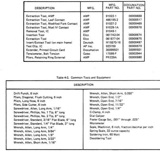
The following tables list tools and equipment required to perform removal, replacement and adjustment procedures described in this section.
Table 4-1. Special Tools and Equipment
MFG. DOCUMATION
DESCRIPTION MFG. PART NO. PART NO.
Extraction Tool, AMP AMP 91022-1 00000688
Extraction Tool, Leaf Contact AMP 465195-2 00000517
Extraction Tool, Modified Fork Contact AMP 91037-2 00000469
Extraction Tool, Mod IV Contact AMP 91029-1A 00000676
Removal Tool, IC AMP 91049-1
Insertion Tool Elco 061742-04 00000674
Extraction Tool Elco 061877-04 00000675
Insert/Extract Tool (on main frame) Deutsch M15570-16 00000487
Test Clip, IC AP Inc. 923700 00000679
Extender, Printed Circuit Card Documation 30099501 30099501
Tensiometer, Belt Tension Gates 17599-F 00003944
[image:12.618.61.583.192.683.2]Pliers, Retaining Ring External AMP PR229A 00000680
Table 4-2. Common Toois and Equipment
DESCRIPTION
Drift Punch, 6 inch
Pliers, Diagonal, Flush Cutting, 6 inch Pliers, Long Nose, 6 inch
Pliers, Side Cutter, 6 inch
Screwdriver, Allen, Long Arm, 1/16" Screwdriver, Phillips, No.1 Tip, 6" long Screwdriver, Phillips, No.2 Tip, 6" long
Screwdriver, Standard, 3/16" Flat Blade, 6" long Screwdriver, Standard, 1/4" Flat Blade, 3" long Wrench, Allen, Long Arm, 1/4"
Wrench, Allen, Long Arm, 9/64" Wrench, Allen, Long Arm, 1/8" Wrench, Allen, Long Arm, 3/32" Wrench, Allen, Short Arm, 1/16"
Wrench, Allen, Short Arm, 0.050" Wrench, Open End, 1/2"
Wrench, Open End, 7/16" Wrench, Open End, 11/32" Wrench, Open End, 1/4" C-Clamp,4 inch
Dial Caliper
Feeler Gauge Se.!, .001" through .025" Micrometer
Scale, Machinist, 6 inch, fraction/decimal per inch Spring Scale, 32 ounce capacity
Soldering Iron, 60 Watt Desoldering Tool
4.3 TROUBLESHOOTING
b.
If a malfunction occurs in a Model RM card reader that
cannot be corrected with operator maintenance procedures c.
(paragraph 2.5) a maintenance technician should be called to isolate and correct the problem. The fault isolation flow charts (Figures 4-1 through 4-12) are p!ovided to assist the technician in isolating problems that may occur in the d. reader.
4.4 COMPONENT MAINTENANCE PROCEDURES e.
4.4.1 ADJUSTMENTS
Adjustments should be checked when minor malfunctions occur and before major repair is attempted. They must also
f.
be effected after major repair and component replacement. g.
Adjustment procedures are included where applicable.
Loosen set screw in timing disc and remove disc (Figure 4-15).
Loosen three motor mounting plate screws on underside of main frame (Figure 4·16). Remove fourth screw.
Loosen set screw in bottom fourth stacker roller pulley (Figure 4·15).
Remove bottom fourth stacker roller pulley and third stacker roller drive belt (Figure 4-17).
Loosen set screw in fifth stacker roller pulley (F igure 4·15).
Remove fifth stacker roller pulley from shaft.
h. Remove main drive motor belt (Figure 4·17).
4.4.2 ACCESS COVER REMOVAL AND
INSTALLATION
To perform maintenance procedures detailed in this section, it may be necessary to remove the front panel, track cover and/or rear panel.
a. Remove six screws from front panel (Figure 4-13).
then remove panel.
b. Remove four screws from track cover (Figure 4-13), then remove cover.
c.
d.
e.
4.4.3
Remove six screws from rear panel (Figure 4-14).
Move rear panel out slightly, disconnect fan cable then remove rear panel.
To replace access covers, reverse the above procedure (steps d. through a.)
MAIN DRIVE MOTOR BELT
4.4.3.1 Removal and Installation
a.
4·2
Remove front and rear panels (paragraph 4.4.2).
CAUTION
WHEN HANDLING TIMING DISC, BE EXTREMELY CAREFUL NOT TO DAMAGE THE TEETH. WRAP THE DISC IN TISSUE WHILE IT IS REMOVED FROM READER.
i.
j.
k.
CAUTION
PULLEY CONFIGURATION MUST BE MAINTAINED. ALWAYS REPLACE PROPER PULLEY I N ITS CORRECT POSITION (UPPER OR LOWER) ON THE PROPER SHAFT. FIGURE 4·18 SHOWS THE CORRECT CONFIGURATION.
Install replacement belt around main drive motor pulley and top fourth stacker roller pulley.
Place belt over fifth stacker roller shaft and replace fifth stacker roller pulley on shaft.
Replace third stacker roller drive belt and bottom fourth stacker roller pulley.
I. Align bottom fourth stacker roller pulley set screw with flat side of shaft and carefully tighten set screw.
CAUTION
APPLY ONLY MODERATE TORQUE TO TIGHTEN PULLEY SET SCREW. OVERTORQUE MAY RESULT IN DAMAGE TO PULLEY.
OPfRATf POWER IiWITCft REPLACE CONTROL PANEL TROUBLfSHOOT CHASSIS WIRING RETURN UNIT TO SERVICE RfPLACf INOICATOR LAMP YES REPLACE FUSE Fl
REPLACE TRANSFORMER Tl REPLACE TRANSfORMER T2 RfSTORf SOURCE POWER TROUBLESHOOT CHASSIS WIRING RfPLACf CIRCUIT BREAKER CBl REPLACE 6 VOLT
NO POWER SUPPLY REPLACE SOLENOID DRIVER ASSEMBLY REPLACE DIODE BRIDGE DB2 TROUBLfSHOOT CHASSIS WIRING REPLACE CAPACITOR Cl REPLACE DIODE BRIDGE OBI TROUBLEIiHOOT CHASSIS WIRING REPLACE POWER CORD REPLACI: FILTER fLt TROUBLESHOOT CHASSIS WIRING
INITIAL TROUBLE SYMPTOM, POWER indicator 'aU. to iIIuminale. RETURN UNIT TO SERVICE A881 Fiou..,4·1 Fault Isolation Olart. AC Power
RETURN
UNIT TO SERVICE
OOES
CeloPEN WiTH DfliVE MOTOR
OISCONNECTEO ? REPLACE fAN ASSEMBLY
~~-c~.c =~_. _ _ _ _ _ _ _ _ _ _ _ _ _ _ _ _ _ _ _ _ _ _ _ _ _ _ _
DOES
Cpl0PEN WIT ... FAN
DISCONNECTED ?
REPLACE DRIVE MOTOR
REPLACE DEfECTIVE DRIVi ROLLER BEARING
NO
REPLACE BLOWER MOTOR
YES RETURN UNIT TO SERViCE
REPlACE
BLOWER
TROUBLESHOOT CHASSIS WIRING
INITIAL TROUBLE SYMPTOM:
Cncuit breaker COl is toppea.
A989
Figure 4-2
fauh lsolduofl C.iart. AC Circuit Breaker
--.--~ .. -
-.~.-.---~---IS THERE
SKEWING OF YES CARDS AS THEY ARE
PASSEO THRU READ STA.
7
REPlAC£ TIMING
CARD
NO REPLACE TRANSFER CARD
NO ADJUST PINCH ROLLER TENSION
ADJUST paCK
SUPPORT CASTING
ADJUST
MAIN DRIVE BELT
NO REPLACE FAULT CARD
REPLACE
SEOUENCE CARD
REPLACE/ADJUST MAGNETIC PICKUP
REPLACE SINGLE PIECE READ/LIGHT STATION
TROUBLESHOOT CHASSIS WIRING
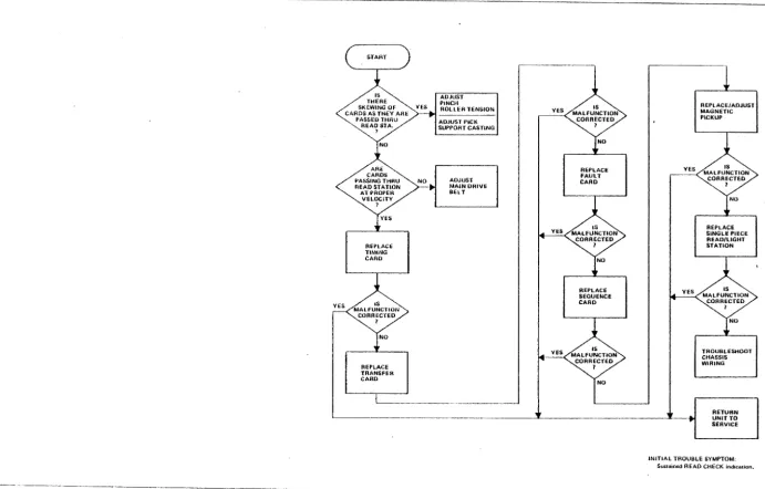
RETURN UNIT TO SERVICE INITIAL TROUBLE SYMPTOM;
Sustained READ CHECK indication.
[image:16.807.61.752.94.536.2]- - - -_ _ _ _ _ _ _ _ _ _ _ _ _ _ _ _
~A990
figure 4-3
FuUlt Isolalion Chari, Read Check
..J CD ::i!
a:
00 o
N IJ)
"
REPLACE LAMP IN MALFUNCTION· ING INDICATOR
RETURN UNIT TO SERVICE
TROUBLESHOOT POWER
CIRCUIT (FIGURE 4-1)
REPLACE FAULT CARD
REPLACE FAULT CARD
TROUBLE· SHOOT CHASSIS WIRING
YES YES
TROUBLESHOOT CHASSIS
RETURN UNIT TO SERVICE WIRING
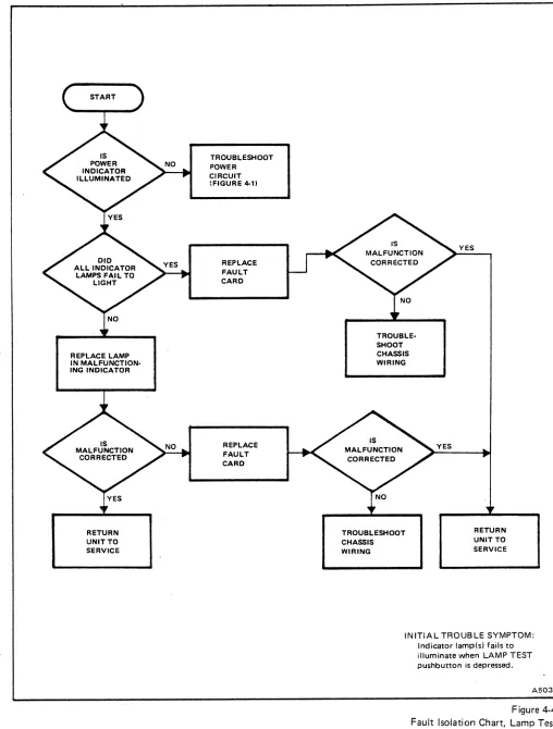
INITIAL TROUBLE SYMPTOM: Indicator lamp(s) fails to illuminate when LAMP TEST pushbutton is depressed.
[image:17.612.64.572.57.727.2]A503
Figure 4-4 Fault Isolation Chart, Lamp Test
c-~~:~-)
~
/ ' STACK ~
~
CONDITION EXIST'ILARO ENTERS REAl) '-.. YES
ST A nON BEFORE PREVIUUy)
-.''''. C"':T~ij~~\AS /~~
YES
,
NO
REPLACE
TRANSFER
CARD
REPLACE
FAuLT
CARD IS
MALfUNCTlOt!
CORRECTED
,
~NO YES
RETuRN
UNIT TO
SERVICE
REPLACE STACK
PHOTOCELL
REPLACE.
S"rACKER lEO
IS
MALFUNCTION
.... ~AR~CTED
~/
NO TROUBLESHOOT
CHASSIS
WIRlNG
REPLACE
DAMAGED CARDS
ADJUST
~N_O _ _ ~ ~~~I~~ROAT STACK PHOTOCEll
MALFJ~CTlON >-,Yc;E",S,---, CORRECTED
1
NO TROUillESHOOT CARO HANDLING COMPONENTS
RETURN UNIT TO SERVICE
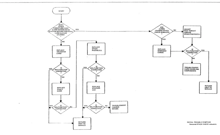
INITIAL TROUBLE SYMPTOM SuUained ST ACK CHECK mdlcatlon,
[image:18.797.52.766.88.525.2]A994
Figure 4·5
Fault isoiatiull Chart, Stuck Check
MAL FUNCTION NO COHRECH::D
?
".oS
At:rUHN
UNIT TO
SEHVICE TROUUl ESHOOT CHASSIS WIRING YES PEttFORM PINCH ADJUSl'MENT NO YES
REPl,ACE on
TIGHTEN
VACUUM HOSE
NO
YES
TROUULESHOOT
VACUUM PUMP
ASSEMBLY (FIGURE 4-12)
ADJUST
PICK VACUUM
TUBE HEPLACE FAULT CARD REPAIR DEFECTIVE
WIRING OR
CONNECTOHS SUffiCIENT RIFflE AIR ? NO YES REPlACE OR l"IGHTEN
BLOWER HOSE
YES
REPLACI:
RifFLE
AIR CAP
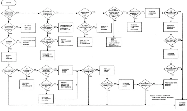
DOES ...
PICKER PICK
CAROSWHEN
SECTOR IS OPERATED BY HAND NO CLEAN PICK SECTOR PERfORM PICK SECTOR ADJUSTMENT REPLACE TIMING CARD IS MALFUNCTION CORRECTED I NO_ .. YES YES REPLACE TRANSFER CARD YES REPLACE
PICK SHAFT AND BEARINGS --REPLACE SEOUENCE CARD REPLACE SOLENOID DRIVER NO REPLACE SOLENOID IS
M~:~~g~~N
>-N:.:O'--__
-lI>I TROUBLESHOOT CHASSIS WIRINGI
YES
INITIAL TROUBLE SYMPTOM,
PICt< CHECK indicatOf illumioatoo
I~ustajned Of flashiog).
[image:19.803.36.762.101.530.2]~-~-~~---~-~~-- ---1---~---~I-~---___tof RETURN UNIT TO SERVICE - - --- ~--~-~~---AS86 Figure 4·6 Fault Isolation Chart, Pick Check
INITIAL TROUBLE SYMPTOM,
HOPPER CHECK indicator f .. ib. to illuminate whlW chuck condhion tlklsn.
A421
INITIAL TROUBLE SYMPTOM,
$um.hwd HOPPER CHECK indicadon.
A420
Figur.4-7 Fault Isolation Chart. Hopper Check
TROUBLESHOOT AC POW£R CIRCUITS IflGURE 4-11
INPUT HOPPER EMPTY 1 YES LOAD INPUT HOPPER
NO TROUBLESHOOT STOP CIRCUIT IflGURE 4-101 BLOWER OPERATING PROPERLY 1 REpLAC£
DRIVE MOTOR RUN CAPACITOR C3 REPLACE DRIVE MOTOR 01 NO TROUBLESHOoT CHASSIS WIRING YES NO YES YES REPLACE MOTOR RELAY Kl
CORRECT CHECK CONOITION PER
APPLICABLE flOW DIAGRAM TROUBLESHOOT CHASSIS WIRING RETURN UNIT To SERVICE YES REPLACE TRANSFER CARD TROUBLE IS
IN HOST SYSTEM oRI/OCAOLE
INITIAL TROUBLE SYMPTOM: START switch will n01 ini1iate reader operation.
REPLACE SEQUENCE CARD REPLACE fAULT CARD REPLACE CONTROL PANEL NO TROUBLESHOOT CHASSIS WIRING AB8Q Figura 4·8 Fault l.ol.tion Chart, Start Function
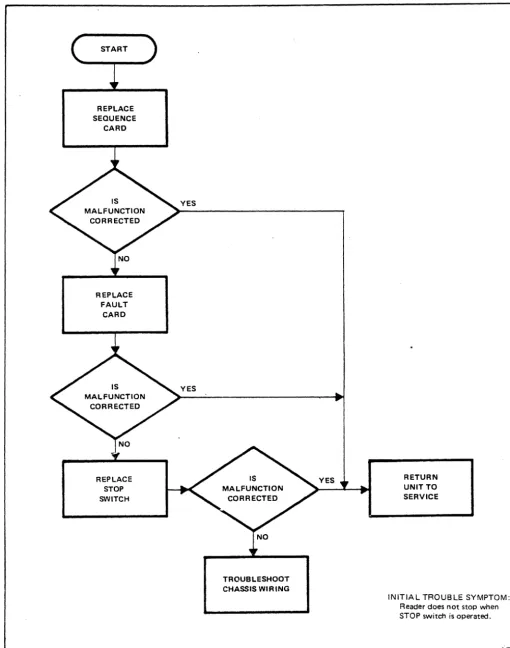
REPLACE SEQUENCE
CARD
REPLACE FAULT
CARD
REPLACE STOP SWITCH
YES
YES
TROUBLESHOOT CHASSIS WIRING
RETURN UNIT TO SERVICE
INITIAL TROUBLE SYMPTOM: Reader does not stop when STOP switch is operated.
[image:22.624.71.582.60.709.2]A501
Figure 4-9 Fault Isolation Chart, Stop Function
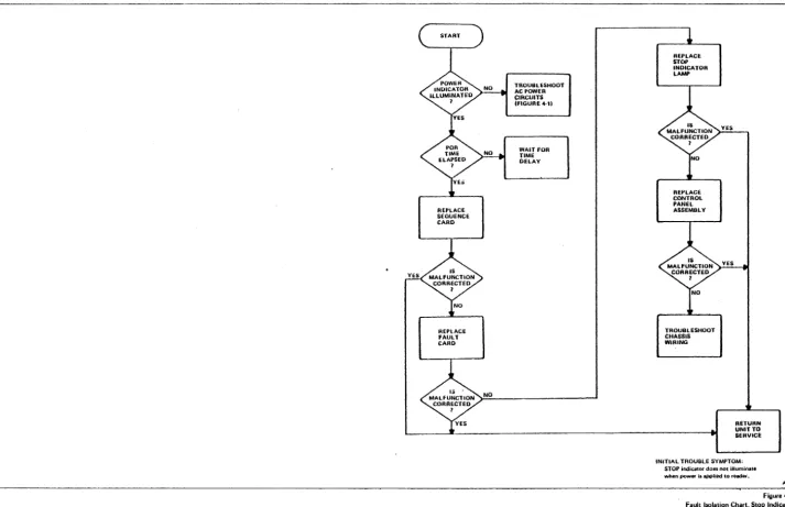
REPLACE SEOUENCE CARD
REPLACE FAULT CARD
NO
TROU8tl:SHOOT
AC POWER CIRCUITS IFIGURE 4-11
WAIT FOR TIME DELAY
REPLACE STOP INDICATOR
LAMP
REPLACE CONTROL PANEL ASSEMBLY
TROUBLESHOOT CHASSIS WIRING
RETURN UNlfTO SERVICE INITIAL TROUBLE SYMPTOM,
STOP indiutor doa5 nOl Utumioa'8 when powPI' li applied to reader.
Figure 4-10 Fault 150lation Chart, Stop Indication
[image:23.805.47.761.94.555.2]
-REPLAct TRJ,NSFER CARD
NO
REPLACE TIMING
CARD
REPLACE
SEOUENCE CARD
TROUBLE IS IN HOST SYSTEM OR I/O CABLE
REPLACE FAULT CARD
REPLACE SOLENOID DRivER
REPLACE PICKER BEARINGS ANO SHAFT
RETURN UNIT TO SERVICE
REPLACE
SOLENOID
REPLACE
TRANSFORMER
T2
REPLACE DIODE BRIDGE
002
TROUBLESHOOT CHASSIS WIRING INITIAL TROUBLE SYMPTOM,
Ef(alic: card picking or ward, nOI being picked.
A99J
Figure 4-\\
faull Isolation Chart. Card Pick Function
MECHANICAL BINDING OF
BLOWER
I
YES
REPLACE
BLOWER IS MALfUNCTION
CORRECTED
I
NO
REPLACE
BLOWER MOTOR
B2
YES
RETURN UNIT TO SERVICE
NO
REPLACE FAULT CARD
REPLACE
MorOR CONTROL RELAY
Kl
TROUBLESHOOT CHASSIS WIRING
ADJUST OR
REPLACE BLOWER DRIVE BELT
NO
REPLACE OR TIGHTEN BLOWER HOSE
REPLACE BLOWER MOTOR RUN CAPACITOR C4
REPLACE
BLOWER MOTOR
B2
TROUBLESHOOT CHASSIS WIRING
YES
YES
RETURN UNIT TO SERVICE INITIAL TROUBLE SYMPTOM,
Picker vacuum and/or rittle Mir pressure low or absent.
A991
-.---~----~~
figure 4-12 Faull Ioolation Chart, Blower System
TRACK COVER SCREWS (4)
FRONT PANEL SCREWS (6)
Figure 4-13. Removal of Front Panel and Track Cover
c:=::::l c:=::::l c:=::::l c:=::::l c:=::::l c:::::) c:=::::l c:=::::l c:=::::l ~ ~~
~ c::::;) c::::;) c::::;) c::::;) ~
c::::;) c::::;)
~ c:=::::l ~~
REAR PANEL SCREWS
c:::::l c:::::l c:::::l c:::::l c:::::l c:::::l
<==' -==>
c:::::l c:::::l c:::::l c:=::::l c:::::l c:::::l c:=::::l c:::::l
REAR PANEL SCREWS
Figure 4-14. Removal of Rear Panel
SHUTDOwN
MAN
®
AUTOA57S
A579
SET SCREW
4-28
SET SCREWS
FOURTH STACKER ROLLER PULLEYS
SET SCREWS
Figure 4-15. Stacker Drive Train Pulley Arrangement
MOTOR MOUNTING SCREWS
REMOVE THIS SCREW
Figure 4-16. Main Drive Motor Mounting
SET SCREW
TIMING DISC
TIMING DISC SET SCREW
SET SCREWS
P012
FIRST STACKER
DRIVE BELT SECOND STACKER DRIVE BELT _
MAIN DRIVE MOTOR PU LLEY
MAIN DRIVE MOTOR BELT
Figure 4-17. Stacker Drive Train Belt Arrangement
/---~'
,~
20127008
RM600L
, ... - - - " "
IS-Tooth (60 Hz)
lsXl037
RM1000L
16XL037
20127006
18-Tooth (50 Hz)
lsXL037
80XL02s
20080404
IS-TOOTH
20127007
14-Tooth
20127009
I6-Tooth
16XL037I
20080401
14-Tooth
80XL025
20080404
IS-Tooth
(60 Hz)
(50 Hz)
20080401
I4-Tooth
'-IsXL037
lsXL037
---7QXL025
I4XL037
201270041
(60
Hz)
20127003
-(SO
HZ_) ...1 _ _""_
20127003
Figure 4-18. Pulley and Belt Configuration
P160
MAIN DRIVE MOTOR BELT
-20127003
20127004D..
(60 Hz)
20127003
(50 Hz)
A639
n. Align fifth stacker roller pulley set screw with flat b. side of shaft and carefully tighten set screw.
Loosen set screw in magnetic pickup mounting block (Figure 4·19).
o. Replace timing disc on fifth stacker roller shaft and c. lightly tighten set screw.
Remove magnetic pickup.
p.
q.
Adjust main drive motor belt tension (paragraph 4.4.3.2).
Adjust timing disc (paragraph 4.4.4.2).
4.4.3.2 Tension Adjustment
The drive motor belt tension is adjusted to ensure constant
d. Disconnect magnetic pickup leads at connector.
e.
f.
g.
I nsert replacement' pickup into mounting block (Figure 4·19).
Connect pickup leads at connector.
Adjust magnetic pickup (paragraph 4.4.4.2).
card speed and timing. 4.4.4.2 Adjustment
a.
b.
Loosen four motor mounting plate screws (Figure 4.16).
CAUTION
THE DRIVE MOTOR BELT TENSION IS CR ITICAL. TOO MUCH TENSION CAN CAUSE EXCESSIVE WEAR OF DRIVE ROLLER BEARINGS. IT MAY ALSO CAUSE DEFLECTION OF DRIVE ROLLER SHAFTS RESULTING IN READ CHECKS. TOO LITTLE TENSION MAY CAUSE BELT TO SLIP RESULTING IN ERRATIC TIMING, INCORRECT DATA AND/OR READ CHECKS.
The magnetic pickup is adjusted to ensure that timing pulses of optimum level and modulation ratio (run-out) are developed. There are two adjustments: horizontal alignment and air gap (Figure 4-20). If either of these adjustments is incorrect, card synchronization may be erratic and cause read checks.
CAUTION
IF THE TIMING DISC MUST BE REMOVED, HANDLE IT WITH CARE. DAMAGE TO DISC MA Y R ESUL T IN ERRONEOUS CARD PROCESSING.
The motor mounting plate should slide back and
a.
forth freely. Loosen timing disc set screw.
c.
d.
Pull motor and mounting plate back until tension is applied on drive motor belt. Tighten the four motor mounting plate screws just enough to hold motor in place.
Check drive motor belt tension by deflecting belt at point shown in Figure 4-16. Belt should deflect between 0.25 and 0.50 inch before side play of pulley shaft is discernible.
e. Repeat steps c. and d. until required deflection is b.
c.
d.
e.
Position timing disc on shaft to align it in a horizontal plane with center of magnetic pickup tip.
Hold disc in position and tighten set screw on flat side of shaft.
Loosen magnetic pickup set screw.
Position magnetic pickup assembly to adjust air gap between pickup and timing disc. Initial air gap should be 0.006 ± 0.001 inch.
obtained, then tighten motor mounting screws. f. Remove card cage rear panel and place Timing Card
(J3) on an extender board.
4.4.4 MAGNETIC PICKUP AND TIMING DISC
4.4.4.1 Replacement
a' Remove rear panel (paragraph 4.4.2).
4·30
g. Connect an oscilloscope across magnetic pickup
output (J3·S and J3-T).
TIMING MAGNETIC
DISC PICKUP TIP
MAIN FRAME SET SCREW
A365 Figure 4-19. Magnetic Pickup Replacement
AIR GAP
A334 Figure 4-20. Magnetic Pickup Adjustments
CAUTION
MINIMUM PERMISSIBLE AIR GAP BETWEEN TIP OF MAGNETIC PICKUP AND TEETH OF TIMI NG DISC IS 0.003 INCH.
b. Loosen set screw in bottom second stacker roller pulley (Figure 4·151.
c. Move pulley downward to disengage first stacker roller drive belt. Remove pulley and belt.
i. Carefully adjust magnetic pickup to obtain output d. 1nstall replacement first stacker roller drive belt around first stacker roller pulley and second stacker roll er shaft.
waveform shown in Figure 4-21.
1. Output level should measure between 1.5 and
6.0 volts peak-to-peak. . e. Replace bottom second stacker roller pulley on shaft to engage first stacker roller drive belt. Position pulley against top second stacker roller pulley. 2. Modulation ratio should not exceed 2: 1.
j. Remove reader power; remove extender board and f. Align bottom second stacker roller pulley set screw with flat side of shaft and carefully tighten set screw. install timing card in its normal position.
k. Replace rear panel and card cage rear panel. 4.4.5 THIRD STACKER ROLLER DRIVE BELT a. Remove front and rear panels (paragraph 4.4.21.
b.
c.
d.
e.
f.
Loosen set screw in bottom fourth stacker roller pulley (Figure 4-151.
Move pulley downward to disengage third stacker roller drive belt. Remove pulley and belt.
Install replacement third stacker roller drive belt around bottom third stacker roller pulley and fourth stacker roller shaft.
Replace bottom fourth stacker roller pulley on shaft to engage third stacker roller drive belt. Position pulley against top fourth roller pulley.
Align bottom fourth stacker roller pulley set screw with flat side of shaft and carefully tighten set screw.
CAUTION
APPLY ONLY MODERATE TORQUE TO TIGHTEN PULLEY SET SCREW. OVERTORQUE MAY RESULT IN DAMAGE TO PULLEY.
g. Replace front and rear panels.
4.4.6 FIRST STACKER ROLLER DRIVE BELT a. Remove front and rear panels (paragraph 4.4.21.
4-32
CAUTION
APPLY ONLY MODERATE TORQUE TO TIGHTEN PULLEY SET SCREW. OVERTORQUE MAY RESULT IN DAMAGE TO PULLEY.
g. Replace front and rear panels.
4.4.7 SECOND STACKER ROLLER DRIVE BELT a. Remove front and rear panels (paragraph 4.4.2). b. Remove bottom fourth stacker roller pulley and third
stacker roller drive belt (paragraph 4.4.5.).
c. Remove bottom second stacker roller pulley and first stacker roller drive belt (paragraph 4.4.6).
d. Loosen set screw in top second stacker roller pulley (Figure 4-151.
e. Move pulley downward to disengage second stacker roller drive belt. Remove pulley and belt.
f.
g.
I nstall replacement top second stacker roller drive belt around third stacker roller pulley and second stacker roller shaft.
Replace top second stacker roller pulley on shaft to engage second stacker roller drive belt.
NOTES:
1. Amplified range
=
1.5V to 6.0V POp. 2. Maximum modulation ratio = 2: 1.A494
Figure 4-21. Magnetic Pickup Output
i.
j.
k.
CAUTION
APPLY ONLY MODERATE TORQUE TO TIGHTEN SET SCREW. OVERTORQUE MAY RESULT IN DAMAGE TO PULLEYS.
Replace first stacker roller drive belt and bottom second stacker roller pulley (paragraph 4.4.6).
Replace third stacker roller drive belt and bottom fourth stacker roller pulley (paragraph 4.4.5).
Replace front and rear panels.
4.4.8 FIRST STACKER ROLLER BEARING ASSEMBLY
a. Remove front panel, rear panel and track cover (paragraph 4.4.2).
b. Prop stack follower open to its extended position. c.
d.
e.
Remove bottom second stacker roller pulley and first stacker roller drive belt (paragraph 4.4.6).
Loosen set screw in first stacker roller pulley and remove pulley.
To replace bearing assembly, perform the following:
NOTE
-To assure proper operation, the roller shaft and both bearings should be replaced with a matched assembly.
1. Loosen set screw in bottom roller of stacker roller assembly (Figure 4-22).
2. Lift roller shaft straight up and out of casting. Note that there is a spacer washer between the top roller and the bearing seat. Remove top roller from shaft.
3. To remove top - bearing, lift bearing from stacker casting with an L-shaped tool.
4. To remove bottom bearing, slide bottom roller and spacer washer clear of hole. Use a straight tool to tap edge of bearing from inside of shaft hole to drop bearing from casting.
5. Install new bearings. Place spacer washer on top bearing. Slide bottom roller and spacer washer under shaft hole.
6. Install top roller on new shaft, flush with (or slightly below) end of shaft.
7. Place shaft in shaft hole.
4-34
PHOTOCELL SET SCREW
TOP ROLLER BEARING
~ ;~~~~~~
SPACER WASHER~
BEARINGBEARING
"'--:d~~~~=SPACER
WASHERSETSCREW
LOWER ROLLER
PULLEY
L..-"-y-
r - -
SET SCREW MAINFRAMEFigure 4-22. Stacker Roller Bearing Assembly
DRIVE ROLLER SET SCREW
P004
8. Select a feeler gauge (.005 to .025 inchl that g. will just force bottom roller against bearing when inserted between bottom roller and top
surface of main frame. h.
9. Apply firm pressure on top roller and tighten i. set screw in bottom roller.
Replace first stacker roller drive belt and bottom second stacker roller pulley (paragraph
4.4.61.
Return stack follower to its normal position. Replace front panel, rear panel and track cover. 4.4.10 THIRD STACKER ROLLERBEARING ASSEMBLY 10. Check for vertical end play in stacker roller
shaft assembly. If there is discernible vertical end play, loosen set screw in bottom roller and a. repeat steps 8 and 9.
f. Replace first stacker roller pulley on first stacker b.
g.
h.
roller shaft in position shown in Figure 4-15.
Align first stacker roller pulley set screw with flat side of shaft. Carefully tighten set screw.
CAUTION
APPLY ONLY MODERATE TORQUE TO TIGHTEN PULLEY SET SCREW. OVERTORQUE MAY RESULT IN DAMAGE TO PULLEY.
Replace first stacker roller drive belt and bottom c.
d.
e.
f.
second stacker roller drive pulley (paragraph
4.4.61.
g.i. Return stack follower to its normal position.
h.
j. Replace front panel, rear panel and track cover.
4.4.9 SECOND STACKER ROLLER i.
BEARING ASSEMBLY
a. Remove front panel, rear panel and track cover j. (paragraph
4.4.2).
b. Prop stack follower open to its extended position. c. Remove bottom second stacker roller pulley and first
stacker roller drive belt (paragraph
4.4.61.
d. Remove top second stacker roller pulley and second stacker roller drive belt (paragraph
4.4.7).
e. Following procedure of paragraph
4.4.8,
step e., k. replace bearing assembiy.f. Replace second stacker roller drive belt and top I. second stacker roller pulley (paragraph
4.4.7).
Remove front panel, rear panel and track cover (paragraph
4.4.2).
Prop stack follower open to its extended position. Remove bottom second stacker roller pulley and first stacker roller drive belt (paragraph
4.4.6).
Remove bottom fourth stacker roller pulley and third stacker roller drive belt (paragraph
4.4.5).
Loosen set screw in bottom third stacker roller pulley. Remove pulley.
Remove top second stacker roller pulley and second stacker roller drive belt (paragraph
4.4.71.
Loosen set screw in top third stacker roller pulley. Remove pulley.
Following procedures of paragraph
4.4.8,
step e., replace bearing assembly.Replace top third stacker roller pulley on third stacker roller shaft in position shown in Figure 4-15. Align top third stacker roller pulley set screw with flat side of shaft. Carefully tighten set screw.
CAUTION
APPLY ONLY MODERATE TORQUE TO TIGHTEN PULLEY SET SCREWS. OVERTORQUE MAY RESULT IN DAMAGE TO PULLEYS.
Replace second stacker roller drive belt and top second stacker roller pulley (paragraph
4.4.7).
Replace bottom third stacker roller pulley on third stacker roller shaft.m. Align bottom third stacker roller pulley set screw I. with flat side of shaft. Carefully tighten set screw.
Vacuum pump assembly may now be removed from reader.
n. Replace third stacker roller drive belt and bottom 4.4.11.2 Belt Adjustment
fourth stacker roller pulley (paragraph 4.4.5).
o.
Replace first stacker roller drive belt and bottom second stacker roller pulley (paragraph 4.4.6).p. Return stack follower to its normal position.
q. Replace front panel, rear panel and track cover.
4.4.11 VACUUM PUMP ASSEMBLY
4.4.11.1 Removal
Vacuum pump belt tension is a critical adjustment. A reduction in vacuum or riffle air can cause erratic card picking. The vacuum pump assembly "must be removed to perform this adjustment.
a. Remove vacuum pump assembly from the reader.
b.
c.
Loosen three vacuum pump mounting bolts, slide pump toward motor and remove belt (Figure 4-26).
Replace vacuum pump belt.
a.
Remove front and rear panels (paragraph 4.4.2), d. Using a spring scale, adjust vacuum pump for a belttension of 4 to 6 ounces (about 3/64-inch belt deflection).
b.
c.
Remove four screws from rear of subframe panel assembly (Figure 4-23).
Remove five subframe panel screws from underside of
e. Tighten mounting bolts while maintaining tension.
base plate. f. Replace vacuum pump assembly (paragraph
4.4.11.3). d. Cut cable tie holding output cable to base plate. Move
subframe panel back and down. 4.4.11.3 Installation
e.
f.
g.
Disconnect vacuum pump motor cable.
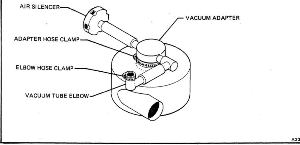
Loosen blower hose clamp under pick support casti ng and remove blower hose from adapter ring (Figure 4-24).
Loosen clamp holding vacuum adapter on top of blower and remove adapter (Figure 4-25).
h. Remove ground strap from vacuum pump mounting
plate.
i.
k.
Tilt reader to gain access to four mounting plate screws from underside of reader.
CAUTION
IN STEP K, HOLD MOUNTING POSTS WITH A 1/2·INCH OPEN-END WRENCH TO AVOID TWISTING OFF THE PUMP PLATE RUBBER SHOCK MOUNTS.
Remove four screws holding pump assembly
a.
b.
Place pump assembly in reader.
Tilt reader to gain access to underside of reader.
CAUTION
IN STEP C, HOLD MOUNTING POSTS WITH
A 1/2-INCH OPEN~END WRENCH TO AVOID
DAMAGE TO RUBBER SHOCK MOUNTS.
c. Install four screws to attach pump assembly
mounting posts to reader base plate.
d.
e.
f.
Connect ground strap to vacuum pump assembly mounting plate.
Install vacuum tube adapter on top of blower and tighten clamp.
Install blower hose on adapter ring under input hopper riffle cap and tighten hose clamp (Figure 4-24).
mounting posts to reader base plate. g. Connect motor cable.
-' co :!:
a:
(Xl 0 N Cl,...
h.
Secure output cable to base plate with cable tie.i. Replace subframe panel assembly. j. Replace front and rear panels.
4.4.12 PICK SUPPORT ASSEMBLY
The pick support assembly must be removed to replace the fourth and fifth stacker roller bearing assemblies and the first and second picker roller bearing assemblies.
4.4.12.1 Removal
To remove the pick support assembly, proceed as follows: a. b.
c.
d.
e. f.g.
h.
i. j.k.
I.Remove front and rear panels and track cover (paragraph 4.4.2).
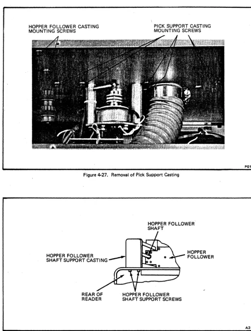
Remove two screws holding hopper follower casting (Figure 4-27).
Remove two screws holding hopper follower shaft support casting (Figure 4-28).
Remove hopper follower shaft and shaft support casting.
Pull hopper follower beyond rear of main frame sufficiently to expose negator spring screw on underside.
Remove negator spring screw and guide spring back onto roller. Remove hopper follower.
Loosen vacuum tube elbow hose clamp (Figure 4-25). Slide elbow off vacuum tube and move to left.
Loosen adapter clamp screw at top of vacuum pump assembly and remove adapter.
Loosen screws on two large hose clamps and remove blower hose.
Remove solenoid return spring (Figure 4-29). Loosen two upper set screws in solenoid coupling. Disconnect solenoid leads at connector.
m. Remove two solenoid mounting plate screws, remove solenoid assembly and carefully set aside.
n.
Remove six screws holding pick support casting (Figure 4-28).o. Remove cable tie holding read station cable to solenoid mounting post.
p.
Remove cable tie holding hopper empty switch cable. q. Remove pick support casting (Figure 4-30).4.4.12.2 Installation
a. Position pick support casting in place on main frame.
b.
c.
d.
Apply LOCTITE Grade C and install six pick support casting mounting screws.
Reassembly remaining parts in reverse order of removal. Do not tighten solenoid coupling set screws. Adjust pick sector (paragraph 4.4.18.2).
4.4.13 FOURTH STACKER ROLLER BEARING ASSEMBLY
a.
b.
c.
d.
Remove pick support assembly (paragraph 4.4.12). Remove bottom fourth stacker roller pulley and third stacker roller drive belt (paragraph 4.4.5).
Loosen set screw in top fourth stacker roller pulley and remove pulley.
To replace shaft and bearing assembly, perform the following:
1. Loosen set screw in bottom roller of stacker roller assembly (Figure 4-22).
2. Lift roller shaft straight up and out of casting. Note that there is a spacer washer between the top roller and the bearing seat.
To assure proper operation, the roller shaft, and both bearings should be replaced with a matched assembly.
3.
Loosen set screw in top drive roller and remove from shaft.SUBFRAME PANEL REAR SCREWS
c:::::::J ~ ~~ ~~ c:::::::> c:::::::>
. c:::::::J c:::::::> c:::::::> c:::::::>
c:::::::J c:::::::> c:::::::> c:::::::> • ) c:::=J
c:::::::> c:::::::> c:::::::> c:::::::> c:::::::> c:::::::>
~ c::::l
~~
~ c::::::l
~ ' - - - ,
~ c:::::::>
~ 'c:::::::>
~~
~ c::::::l
'0j)T~. ".~0S:UTO
MOO'
ON LINE ® O F F LINE
Figure 4-23. Removal of Rear Subframe Panel Assembly
BLOWER HOSE CLAMP
GROUND STRAP SCREW
4-38
CLAMP SCREW
ASSEMBLY MOUNTING SCREWS
VACUUM ADAPTER
Figure 4·24. Removal of Vacuum Pump Assembly
SUBFRAME PANEL REAR SCREWS
AS79
AIR SILENCER
VACUUM ADAPTER
ELBOW HOSE CLAMP-_ _
VACUUM TUBE ELBOW
Figure 4-25. Removal of Vacuum Tube Adapter
PUMP MOUNTI NG BOLTS (3)
[image:38.617.73.576.73.317.2]VACUUM PUMP BELT
Figure 4-26. Vacuum Pump Belt Adjustment
A336
A965
4-40
HOPPER FOLLOWER CASTING MOUNTING SCREWS
[image:39.629.50.563.57.730.2]PICK SUPPORT CASTING MOUNTING SCREWS
Figure 4-27. Removal of Pick Support Casting
HOPPER FOLLOWER SHAFT
HOPPER FOLLOWER
SHAFT SUPPORT CASTI NG
~
HOPPER FOLLOWER
REAR OF READER
HOPPER FOLLOWER SHAFT SUPPORT SCREWS
Figure 4-28. Removal of Hopper Follower Assembly
P013
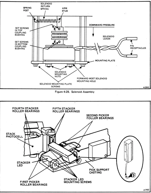
SPRING POST
SETSCREWS IN TOP COUPLING BUSHING SETSCREWS IN BOTTOM COUPLING BUSHING
SOLENOID RETURN SPRING
DOWNWARD PRESSURE
SOLENOID LEADS
C;;!:;::C======:::=I:~::::l""'-
MOUNTING PLATEFOURTH STACKER ROLLER BEAR INGS
STACKER LED
[image:40.612.54.562.50.698.2]SOLENOID MOUNTING PLATE SCREWS
Figure 4-29. Solenoid Assembly
FIFTH STACKER ROLLER BEARINGS
Figure 4-30. Pick Support Casting Removed from Reader
.0.290
.0.782
e.
f.
g.
h.
4-42
4.
To remove top bearing, lift bearing from stack support casting with an L-shaped tool.i. Replace pick ~upport assembly (paragraph 4.4.12),
4.4.14 FifTH STACKER ROLLER
BEARING ASSEMBLY
5. To remove bottom bearing, slide bottom roller and spacer washer clear of shaft hole. Use a straight tool to tap edge of bearing from inside of shaft hole to drop bearing from casting.
a. Remove pick support assembly (paragraph 4.4.12).
6.
7.
Install new bearings. Place spacer washer on top bearing. Slide bottom roller and spacer washer under shaft hole.
Install top roller on new shaft flush with (or slightly below) end of shaft.
8. Place new shaft with top roller installed, in shaft hole.
9. Select a feeler gauge (.005 to .025 inch) that will just force bottom roller against bearing
b.
c.
when inserted between bottom roller and top d.
surface of main frame.
10. Apply firm pressure on top roller and tighten e. set screw in bottom roller.
11. Check for vertical end play in stacker roller shaft assembly. If there is discernible vertical f. end play, loosen set screw in bottom roller and repeat steps 9 and 10.
Place main drive motor belt on motor pulley, on fifth stacker roller pulley, and around fourth stacker roller shaft. Hold belt in this position.
Place top fourth stacker roller pulley on its shaft. Move pulley up on the shaft until it engages main drive motor belt and is just clear of underside of main frame.
CAUTION
APPLY ONLY MODERATE TORQUE TO TIGHTEN PULLEY SET SCREW. OVERTORQUE MAY RESULT IN DAMAGE TO PULLEY.
g.
h.
CAUTION
WHEN HANDLING TIMING DISC, BE EXTREMELY CAREFUL NOT TO DAMAGE THE TEETH. WRAP THE DISC IN TISSUE
WHILE IT IS REMOVED FROM ~EADER.
Loosen set screw in timing disc and remove disc (Figure 4·15).
Loosen set screw in fifth stacker roller pulley and remove pulley.
Following procedure of paragraph 4.4.13, step d., replace bearing assembly.
Place main drive motor belt on motor pulley, on fourth stacker roller pulley, and around fifth stacker roller shaft. Hold belt in this position.
Place fifth stacker roller pulley on its shaft. Move pulley up on the shaft until it engages main drive motor belt and is just clear of underside of main frame.
CAUTION
APPLY ONLY MODERATE TORQUE TO TIGHTEN PULLEY SET SCREW. OVERTORQUE MAY RESULT IN DAMAGE TO PULLEY.
Align fifth stacker roller pulley with flat side of shaft. Adjust pulley, if necessary, to align main drive motor belt with motor pulley and fourth stacker roller pulley. Carefully tighten set screw.
Verify main drive motor belt tension adjustment (paragraph 4.4.3.2).
i. Replace timing disc on fifth stacker roller shaft. Align top fourth stacker roller pulley with flat side of
shaft. Adjust pulley, if necessary, to align main drive j. motor belt with motor pulley and fifth stacker roller pulley. Carefully tighten set screws.
Replace third stacker roller drive belt and bottom k. fourth stacker roller pulley (paragraph 4.4.5).
Align timing disc set screw with flat side of shaft. Align timing disc teeth with magnetic pickup. Tighten timing disc set screw.
Adjust magnetic pickup and timing disc (paragraph
I. Replace pick support assembly (paragraph 4.4.12).
4.4.15 PICKER CAPSTAN SHAFT BEARINGS
a.
b.
Remove pick support assembly (paragraph 4.4.12).
To replace first picker capstan shaft bearings:
1.
2.
3.
4.
5.
Loosen set screw in bottom roller of first picker capstan assembly (Figure 4·22).
Pull first picker capstan shaft straight up and out of pick support casting. Remove bottom capstan and spacer and top spacer.
Loosen set screw in top capstan and remove from shaft. Install top capstan on new shaft and tighten set screw.
Remove top and bottom bearings, using an L-shaped tool to pull bearings from pick support casting.
Install new bearings in casting.
6. Place top spacer on shaft.
7.
Install shaft, with spacer and top capstan5.
6.
7.
Install new shaft and retaining ring in shaft hole.
Install spacer and capstan on shaft.
Apply firm pressure to capstan and retaining ring end of shaft, and tighten set screw in capstan.
d. Install pick support assembly (paragraph 4.4.12).
4.4.16 PINCH ROLLER TENSION ADJUSTMENT
Normally all repairs to the stack support assembly can be accomplished without loosening the stack support casting. However, if loosening or removal of the casting becomes necessary, the following adjustment procedure must be performed.
CAUTION
ADJUSTMENT OF THE STACK SUPPORT CAST-ING IS A FACTORY ADJUSTMENT PROCEDURE. IT SHOULD NOT NORMALLY BE ATTEMPTED IN THE FIELD.
installed in shaft hole. a. Remove front and rear panels and track cover
(paragraph 4.4.2).
c.
8. Install bottom spacer and capstan on shaft.
9. Apply firm pressure on top and bottom
capstans and tighten set screw in bottom capstan.
10. Check for vertical end play in first picker capstan shaft assembly. If there is discernible vertical end play, loosen set screw in bottom capstan and repeat substep 9.
To replace either of the second picker capstan shaft bearings:
1. Loosen set screw in capstan.
2. Remove shaft and retain ring, capstan and
spacer.
3.
4.
Remove bearing, using an L-shaped tool to pull bearing from pick support casting.
Install new bearing in casting.
b. c.
d.
e. f. g.Remove maIO card cage cover (Figure 4-31).
Loosen control panel mounting screws.
Install a 4-inch C-clamp across the pick and stack support castings, centered between the first and second picker rollers and between the fourth and fifth stacker rollers.
Loosen stack ,upport casting mounting screws.
Move the stack support casting to a position where the fourth and fifth stacker rollers just make contact with the first and second picker rollers, respectively.
Using a dial caliper, measure the distance from the rear of the stack support casting to the front of the pick support casting, across each set of rollers.
h. Carefully tighten the C-clamp until the measured
distances are 0.010 inch less than measured in step g.
MAIN CARD CAGE COVER
~-"
~--REAR CARD CAGE COVER
[image:43.649.32.545.58.279.2]A315 Figure 4-31. Card Cage Covers and Mounting
i. Tighten the stack support casting mounting screws; 4.4.17.2 Installation check measurements and repeat steps f., g. and h. if
necessary.
j. Remove C-clal1'lp and dial caliper. k. Tighten control panel mounting screws.
I. Replace main card cage cover.
m. Replace front and rear panels and track cover. 4.4.17 SOLENOID ASSEMBLY
4.4.17.1 Removal
a. Remove front and rear panels (paragraph 4.4.2). b. Disconnect solenoid leads at connector.
c.
Remove solenoid return spring from sector shaft spring post and arm on solenoid mounting stanuoffa.
(Figure 4·29). b.
d.
e.
Loosen two upper set screws in solenoid coupling. c. Remove two solenoid mounting plate screws and remove solenoid assembly.
Apply LOCTITE Grade C to the coupling set screws before replacing. LOCTITE Grade C should be applied to all mounting screws except panel screws.
Install solenoid coupling on shaft of new solenoid Tighten coupling set screws on flat sides of shaft.
Note that solenoid mounting holes are not in line with the mounting plate holes. To ensure that solenoid is reinstalled correctly, solenoid leads must extend to the right (viewed from the front of the reader) and forwardmost solenoid mounting hole must be on the right.
Install solenoid on solenoid mounting plate.
Install solenoid assembly on mounting standoffs, sliding top coupling bushing onto pick shaft. Do not tighten upper set screws in coupling.
d. Connect solenoid leads at connector.
f.
g.
4-44
Remove two solenoid mounting nuts and remove
solenoid from mounting plate. e.
Loosen two lower set screws in coupling and remove coupling from solenoid s h a f t . f .
Preload solenoid coupling (paragraph 4.4.18.2 steps r. and 5.).
NOTE
If proper pick action does not result from preloading the solenoid, perform the entire pick sector adjustment (paragraph 4.4.18.2).
g. Replace front and rear panels.
4.4.18 PICK SECTOR
4.4.18.1 Removal and Installation
a. b. c.
d.
e. f. g. h. i. j. k. I.Remove front panel, rear panel and track cover (paragraph 4.4.2).
Remove solenoid(paragraph 4.4.17). Prop open input hopper follower.
Remove retaining ring from top of pick shaft:
Remove spacers under retaining ring.
CAUTION
ALL SPACERS MUST BE INSTALLED WHEN UNIT IS REASSEMB LED.
Loosen two pick sector set screws.
Remove p,ick shaft from underside of main frame top plate.
Remove pick throat (Figure 4·32).
Remove pick sector from rear of pick support casting.
Install pick sector, shaft, all spacers and retaining ring.
Align flat side of shaft with set screws.
Adjust pick sector for 1·5/8 inches from top surface of main frame to middle row of holes on the pick sector.
Hold sector in place and tighten set screws (Figure 4·33).
4.4.18.2 Adjustment
The pick sector is adjusted to ensure that cards are picked properly. There are six adjustments: height, vacuum adapter air gap, pick stop, pick throat, solenoid coupling and pick bumper.
a.
b.
c.d.
e. f. g.h.
i. CAUTIONADJUSTMENTS MUST BE PERFORMED IN THE SEQUENCE STATED.
Check pick sector height adjustment. Distance from top surface of main frame top plate to center of middle row of holes in pick sector should be 1.625
(1·5/8) inches (Figure 4·32).
If height of pick sector requires adjustment, loosen set screws in front of pick sector (Figure 4·33).
Adjust pick sector until middle row of holes in pick sector measures 1.625 inches above top surface of main frame top plate.
Check air gap between pick sector and vacuum adapter plate. The clearance should be 0.002 to 0.003 inch for maximum vacuum with free sector travel. If adjustment is required, loosen hose clamp on vacuum tube adapter elbow located on the underside of main frame (Figure 4·25). Remove elbow from sleeve. Prop hopper follower open.
Loosen vacuum adapter plate set screw (Figure 4·32).
Insert a .002 inch feeler gauge between pick sector and vacuum adapter plate. From underside of main frame push vacuum adapter plate upward and tighten set screw.
Re·install vacuum tube adapter elbow.
Check pick sector rest position. Rear edge of last column of holes in pick sector should line up with center of vacuum adapter plate set screw. Alignment is determined by placement of pick stop. If adjustment of pick stoo is necessary, perform steps j. and k.
m.
Perform pick sector adjustment (paragraph 4.4.18.2). j. Loosen two pick stop screws (Figure 4·33).4-46
REST STOP VERTICAL AL.IGNMENT
-J
PICKER BUMPERADJUSTMENT SCREW
PICK SECTOR
RETAINING RING _ _ _ ...,..~ ... RIFFLE CAP
SCREWS
RIFFLE AIR CAP
PICK
BUMPER
SCREWS
PICK SECTOR
PICK SECTOR
SET SCREWS
INSERT FEELER GAUGE FOR
[image:45.620.27.536.63.384.2]AIR GAP ADJUSTMENT .002 to .003
Figure 4-32. Pick Sector, Rear View
PICK STOP
SCREWS
STACK SUPPORT ASSEMBLY
VACUUM ADAPTER PLATE SET SCREW
HOPPER EMPTY
SWITCH SCREWS
[image:45.620.24.558.408.696.2]PICK
SUPPORT
CASTING
Figure 4.33. Pick Support Assembly, Front View
A969
k.
I.m.
n.
o.
p. q.r.
s.Using a straight edge to gauge pick sector rest position, hold sector in proper alignment, then push pick stop against pick sector and tighten pick stop screws.
Check gap between pick throat and pick sector. The gap should be
0.008
inch.Loosen pick throat screw (Figure 4·32).
Insert a
.008
inch feeler gauge between pick throat and pick sector.Hold pick throat against feeler gauge and tighten screw.
Check solenoid coupling adjustment. The solenoid coupling transfers rotary solenoid motion to the pick sector.
Loosen two set screws in top bushing of. solenoid coupling (Fiqure 4·29).
Depress coupling slightly with fingers and tighten set screII'JS, ensuring one screw is on flat portion of shaft. Remove return spring from sector shaft and check that solenoid coupling return torque is just sufficient to return pick sector to within 0.020 to 0.040 inch of pick stop. Too much torque could result in insufficient drive to the pick shaft.
Install return spring and check solenoid action by picking cards manually while power is applied and drive and blower motors are on.
w.
x.
NOTE
A ,card should be picked normally within a 0.007·inch to 0.013·inch range of sector overtravel, but wi th 0.0 14·i nch overtravel the card should not be picked by the pinch rollers.
Loosen two pick bumper screws (Figure 4·33).
Adjust pick bumper for proper overtravel and tighten screws.
4.4.19 STACK PHOTOCELL ASSEMBLY
4.4.19.1 Removal and Installation
a.
b.
c.
d.
e. f. g.h.
Remove rear panel and track cover (paragraph 4.4.2).
Remove main card cage cover (Figure 4·31).
Remove rear card cage cover plate (Figure 4·31).
Remove logic cards from card file.
Remove three screws holding card cage in place. Move card cage to rear and remount temporarily, using two screws through rear holes in top plate and front holes
in card cage (Figure 4·34).
Cut cable ties to free photocell leads.
Tag leads from photocell and, using AMP tool 465195·2, disconnect leads from card cage.
Loosen set screw in top fourth stacker roller (Figure 4·22). Remove stacker roller and spacer washer.
t. Check adjustment of pick bumper. This bumper
u.
v.
limits pick sector overtravel beyond the point where i. card is delivered to pinch rollers.
Place about 2 inches of cards (250-300) in the input j. hopper. Operate POWER switch to energize read6ll'. '
With reader in OFF LINE, operate START switch k.
and run a few cards into stacker. Depress STOP switch.
Place a
.007
inch feeler gauge against the pick sector side of the pick bumper. Manually operate pick sector. When card reaches pinch rollers the sector should be just touching the feeler gauge. If bumper must be repositioned, perform steps w. andx.
,Loosen photocell set screw in stack support casting (Figure 4·22) and remove photocell (Figure 4·35).
Remove photocell assembly.
Insert new photocell. Align lens of photocell flush with face of stack support casting. Tighten set screw.
CAUTION
DAMAGE TO PHOTOCELL OR CARDS MAY RESULT IF PHOTOCELL EXTENDS BEYOND FACE OF STACK SUPPORT CASTING.
4·48
[image:47.618.47.557.72.709.2]CARD CAGE MOUNTED IN EXTENDED POSITION
Figure 4-34. Card Cage in Extended Position
STACKER PHOTOCELL
Figure 4-35. Location of Stack Photocell
P016
I. Connect photocell leads to proper terminals on card cage.
m. Install new cable ties to replace those removed in step f.
n.
o.
Replace top fourth stacker roller: ensure there is no vertical end play in stacker roller shaft. If end play is descernible, refer to paragraph 4.4.13, step d., for adjustment procedures.
Return card cage to its normal position.
p. Install logic cards in card file (Figure 4-36).
r.
s.
Replace main card cage cover and rear card cage cover plate.
Replace track cover and rear panel.
4.4.20 STACKER LED ASSEMBL Y
To replace stacker LED assembly:
a. Remove pick support assembly (paragraph 4.4.12.1).
b.
c.
Remove four stacker LED assembly mounting screws (Figure 4-30).
R~move cable ties from solenoid mounting plate and disconnect stacker LED at connector.
d. Remove stacker LED assembly.
e. I nstall new stacker LED assembly, connect at
connector and replace cable ties on solenoid mounting plate.
F. Replace pick support assembly (paragraph 4.4.12.2).
~.4.21 HOPPER NEGATOR SPRING
r
0 replace the hopper negator spri ng, perform the:ollowing:
I.
I.
I.
Remove hopper follower shaft support and shaft (Figure 4-28).
Pull follower back past edge of top plate, turn it over, hold negator spring and remove spring screw.
Pull spring from roller and roll new spring onto roller.
Replace spring screw and reassemble hopper follower.
4.4.22 L0WE.R STACKER NEGATOR SPRING
To replace the lower stacker negator spring, perform the following:
a.
b.
c.
d.
Remove front panel and track cover (paragraph
4.4.2).
Remove main card cage cover (Figure 4·31).
Remove two screws holding front stack follower shaft support (Figure 4·37).
Loosen set screw in rear stack follower shaft support (Figure 4·38). Remove stack follower shaft.
e. Pull stack follower beyond front edge of chassis and turn it over.
f. Hold negator spring and remove screw, then pull
spring from roller.
g. Roll new spring onto roller and install screw.
h. Reinstall stack follower shaft.
i.
j.
Perform stack follower adjustment (paragraph
4.4.24).
Replace front panel and track cover.
4.4.23 UPPER STACKER NEGATOR SPRING
To replace the upper stacker negator spring, perform the following:
a.
b.
c.
d.
Remove main card cage cover (Figure 4·31).
Remove upper negator spring retaining screw (Figure
4-38).
Remove spring, roll new spring onto roller, and replace retaining screw.
Replace card cage cover.
4.4.24 STACK FOLLOWER ADJUSTMENT
The stack follower is adjusted to ensure proper movement of cards into stacker.
a. Remove rear panel (paragraph 4.4.2).