Index
1 Introduction to the SYS68K/ISCSI-1
2 Installation
3
Hardware User's Manual
4
Appendix to the Hardware
User's Manual
5
Copies of Data Sheets
6 Firmware User's Manual
7
Appendix to the Firmware
User's Manual
8 User Notes 1
9
User Notes 2
INTRODUCTION TO THE
SYS68K/ISCSI-l
First Edition
October 1986
PART NO. 800114
FORCE COMPUTERS Inc./GmbH
All Rights Reserved
This document shall not be duplicated, nor its contents used for any purpose, unless express permission has been granted.
NOT E
The information in this document has been carefully checked and is
believed to be entirely reliable.
FORCE COMPUTERS makes no
warranty of any kind with regard to the material in this document,
and assumes no responsibility for any errors that may appear in
this document.
FORCE COMPUTERS
reserves the right to make
changes without notice to this, or any of its products, to improve
reliability, performance or design.
FORCE COMPUTERS assumes no responsibility for the use of any
circuitry other than circuitry which is part of a product of FORCE
COMPUTERS GmbH/Inc.
FORCE COMPUTERS does not convey to the purchaser of the product
described herein any license under the patent rights of FORCE
COMPUTERS GmbH/Inc. nor the rights of others.
FORCE COMPUTERS Inc.
727 University Avenue
Los Gatos, CA
95~3~U.S.A.
Phone
Telex
FAX
(4~8)
354 34
l~172465
(4~8)
395 77 18
FORCE COMPUTERS FRANCE SarI
11, rue Casteja
92I~~
Boulogne
France
Phone
Telex
Fax
(I)
462~37 37
2~6 3~4forc-f
(I) 4621 35 19
FORCE COMPUTERS GmbH
Daimlerstrasse 9
D-8~12
Ottobrunn/Munich
West Germany
Phone
Telex
FAX
(~89) 6~~ 91-~ 52419~
forc-d
(~89) 6~9
77 93
FORCE Computers UK Ltd.
No. 1 Holly Court
3 Tring Road
Wendover
Buckinghamshire HP22 6NR
England
Phone
Telex
Fax
(~296)
625456
838~33Table of Contents
1.0 General Information ••••••••••.••••••••••••..•.••••••••••• l-l
1.1
Hardware Features of the SYS68K/ISCSI-1 ••••••.•••• 1-3
1.2
The Hardware Functions •••••••••••••••••••••••••••• 1-4
1.2.1 The Local 68010 CPU ••••••••••••••••••••••••
~•••••• 1-4
1.2.2 The SCSIbus Interface ••••••..•.••••••••••••••••••• 1-5
1.2.3
1.2.4
1.2.5
1.2.6
1.
2.7
1.2.8
The Floppy Disk Interface ..•••••.••.•.••••••••.••• 1-6
The PI/T 68239 . . . 1-6
The Dual Ported RAM ••••••••••••••••••.•••.•••••••• 1-7
The VMEbus Interface •••.•.••.••••••.•••••••••••••• 1-8
The Bus Interrupter Module •••.•••••••••••••••••••• 1-8
The Optional Back Panel ••••••••••••••••••••••••••• 1-9
2.0
Specification of the SYS68K/ISCSI-1 •••••••••••••••••••••• 2-1
3.0 Ordering Information •.•••••••••••..•••••••••••••••••••••• 3-1
List of Figures
1.9 General Information
The SYS68K/ISCSI-l board is a high performance intelligent SCSlbus
controller board which fully supports the SCSI standard.
Up to four floppy drives can be controlled locally, without using
the SCSlbus.
The board provides local intelligence with a 68919 CPU, 68459
DMAC, SCSI Bus Controller (SCSIBC) and Floppy Disk Controller
(FDC).
A 128Kbyte Dual Ported RAM (DPR) is used to store data and
to interface the SYS68K/ISCSI-l board.
Highest throughput is
guaranteed by using a 19MHz 68459 DMAC and the NCR 5386S SCSIBC.
On a single ended SCSlbus, the board works under the powerful
firmware (128Kbyte EPROM area) as initiator or as target.
The SYS68K/ISCSI-l's own SCSlbus 1.0.
j s
software controlled.
Four floppy drives are fully firmware supported, and can also be
accessed via the SCSlbus in the target mode.
The SYS68K/ISCSI-l contains a VMEbus Rev.C/IEEE P1914 compatible
interface to communicate to the host CPUs via its 128Kbyte DPR.
The access address and the Address Modifier code are jumper
selectable.
A Bus Interrupter Module -
BIM 68153 -
is installed
on the board to support fully asynchronous operation with the 4
different software programmable interrupt request channels.
1.1 Hardware Features of the SYS68KiISCSI-l
68919 CPU for local control (19MHz)
68459 OMA Controller for local transfers (19MHz)
Oual Ported l28Kbyte 0 wait state static RAM between the
VMEbus and the local CPU
SCSlbus interface built with the NCR 5386S SCSlbus controller.
Programmable as an initiator or target
Transfer rate via the SCSlbus up to 1.5Mbyte/s
SHUGART compatible floppy interface with the W01772 FOC.
Up
to 4 floppy drives can be controlled independent of the
SCSlbus
All I/O signals available on P2 connector
4 different interrupt request signals to the VMEbus.
Each
channel contains a software programmable IRQ level
(I
to 7)
and vector
Local parallel interface for controlling and monitoring board
functions
VMEbus Rev.C/IEEE Pl914 compatible interface A24:0l6, 08
Watchdog timer controlling correct functions of on-board hard
and software
Status and control LEOs for monitoring local activities
1.2 The Hardware Functions
The local CPU reacts on the commands and initialisation parameters
within the 128Kbyte DPR.
Constant program run times are
guaranteed through the special hardware logic providing Zero wait
state operation from the DPR, independent of the accesses' from the
VMEbus to the DPR.
The SYS68K/ISCSI-l consists of self-test functions as well as a
hardware watchdog timer which controls the activities of the 68010
CPU running with 10MHz.
User supplied programs can be loaded into the DPR and executed by
the local CPU to adapt and extend board functionality.
The local CPU controls the SCSlbus and the floppy disk interface
via local interrupts, and communicates to the host CPU via the DPR
or via interrupt request to the VMEbus, generated
by
a Bus
Interrupter Module.
The I/O signals to be supported through the NCR 5386S are
terminated on the PC board.
The terminators can be removed jn
order to be able to connect more than 3 SCSI devices.
1.2.1 The Local 68010 CPU
A 10MHz 68010 CPU is installed on the SYS68K/ISCSI-l to control
the data traffic between the serial I/O channels and the VMEbus
host CPU(s).
Two EPROMs with a maximum capacity of 128Kbyte are installed on
the SYS68K/ISCSI-l to hold the handling firmware.
Constant zero
wait state operation from the EPROM guaranteeB
ma~jIDumCPU
throughput and a fixed program run time.
The 128Kbyte Dual Ported RAM is also accessible without the
insertion of wait states by using a CPU clock synchronized
arbitration mechanism.
The accesses from the CPU to the DPR are
not delayed if a VMEbus access is pending or being executed.
A local timer, included in the PI/T, is used to interrupt the CPU
for task scheduling, command interpretation and execution.
1.2.2 The SCSlbus Interface
The SYS68K/ISCSI-l contains an NCR 5386S SCSlbus controller and an
NCR 8310 SCSlbus driver/transceiver.
These chips provide the
following features:
Support of the ANSI X3T9.2 SCSI standard
Asynchronous data transfer to 1.5Mbyte per second
Support of both initiator and target modes
Parity generation with optional checking
Support of arbitration
Control of all bus signals except RESET
Doubly-buffered data register
Versatile MPU bus interface
Memory or I/O mapped MPU interface
DMA or programmed I/O transfer
24-bit internal transfer counter
Programmable (re)selection timeouts
Interrupt of MPU on all bus conditions requiring service
SCSI pass parity optional with checking
48rnA driver
The NCR 5386S SCSI Bus Controller communicates with the 68010 CPU
and the 68450 DMAC as a peripheral device.
The SCSI Bus
Controller is controlled by reading and writing the internal
registers which are addressed via the local address bus.
Since the SCSI Bus Controller interrupts the MPU when it detects
an SCSlbus condition that requires servicing, the MPU is free from
polling or controlling any of the SCSlbus signals.
1.2.3 The Floppy Disk Interface
To provide easy connection from the ISC8f-l board to floppy
drives, the ISCSI-l board includes a floppy
dj~kinterface.
The
FDC WDl772 is
able to control up to four fl.)ppy diives (3",
3 1/2" and
5
1/4").
To allow the connection of all
SHUGART-compati~lefloppy Qlsk
drives, the Drive Select signals
~to 3, the Side Select signal
and the single/double density signal are software programrnablp,
1.2.4 The
PIIT
6823~
A
6823~Parallel Interface and Timer Chip is installed on the
SYS68K/ISCSI-l to control and display the status of all on-board
activities.
The FI/T is also used to force and monitor the
interrupt request lines to the Bus Interrupter Module, which
initiates the interrupts to the VMEbus (under control of the host
CPU) .
One handshake pin is used to interrupt the local CPU if the host
CPU accesses a defined location within the DPR.
One output signal
is used to force the SYSFAIL signal of the VMEbus if an onboard
error has been detected or if the board initializes the DPR after
RESET or Power up.
The timer, also included in the PI/T, is the time base for tLe
onboard handling firmware and the scheduler for the macro
comn·lands.
A
watchdog timer, for processor control, is installed on the board
to detect software or hardware errors independent from the onboard
CPU.
For this purpose, one output of the PI/T is used to
retrigger the watchdog timer within defined time frames.
If the onboard CPU does not work properly, or if the hardware
isn't working correctly, the timer will not be retriggered, and
the SYSFAIL signal of the VMEbus will be activated.
The host CPU
then can initiate a software controlled RESET for the ISCSI, or
start other maintenance activities.
The SCSlbus RESET is controlled by the PI/T.
One input of the
PI/T indicates the state of the SCSlbus RESET, and one output
controls the SCSlbus RESET signal.
1.2.5 The Dual Ported RAM
128Kbyte of Dual Ported Static RAM with 45ns access time are
installed on the SYS68K/ISCSI-l to service all applications
requiring fast operations and large amounts of data areas.
The local 68010 CPU runs without the insertion of wait states out
of the DPR, because a CPU clock synchronised arbitration-logic and
a full buffered and latched VMEbus interface is installed on the
SYS68K/ISCSI-l.
Between two CPU access cycles, a VMEbus cycle is
serviced and completed.
On VMEbus Read cycles, the
dat~pattern
is latched, and the internal cycle of the DPR is aborted while the
VMEbus cycle is decoupled.
A partition of the DPR is reserved for the local CPU_ for vector
storage, the program counter, and temporary buffers.
This
partition is used from the VMEbus side for programming the BIM and
initiating an interrupt, which will be handled from the onboard
CPU, or driving a local RESET.
1.2.6 The VMEbus Interface
A full VMEbus Rev.C/IEEE
Pl~14
compatible interface is installed
on the SYS68K/ISCSI-l to allow an access to the DPR and the Bus
Interrupter Module.
The 16-bit data width (D16,D8) of the DPR and the decoding of the
standard address range (A24) allows easy installatio'n in all
VMEbus environments.
During Power-up and after a RESET has been executed from the local
CPU, the SYS68K/TSCS:t:-l drives
the VMEbus signal SYSFATL active
to signal each board in the VMEbus environment that the board is
not ready or has detected a malfunction.
A RESET for the local CPU can be initiated by accessing a
dedicated address within the 128Kbyte boundary of the DPR.
A] 1
local devices as well as the CPU will be reset through this
access.
An interrupt to the local CPU can be forced by accessing another
location within the DPR, signalling the on-board processor that a
command has been given, or that an exception bas to be taken.
The Dual Ported RAM can be accessed at least every
64~nsbecause
this is the worst case cycle time.
The data transfer rate to/from
the SYS68K/ISCSI-l is 3 to 4Mbyte/s including the VMEbus protocol.
best case
average
worst case
Access Time
33~
43~
56~
1.2.7 The Bus Interrupter Module
Cycle Time
63~
To allow fully asynchronous operation, the SYS68K/ISCSI-l contains
a Bus Interrupter Module -
BIM 68153 -
providing 4 individually
programmable interrupt channels.
Each channel is able to force an
interrupt request to the VMEbus.
For each channel, the IRQ level
(1 to 7) as well as the interrupt vector is fully software
programmable.
The local CPU forces the requests to the BIM
program the interrupt vector and the level.
change of the interrupt level and vector
environments.
1.2.8 The Optional Back Panel
2.9 Specification of the SYS68K/ISCSI-l
Local CPU
EPROM
Dual Ported RAM
SCSlbus Interface
Floppy Disk Interface
VMEbus Interface
Handling Firmware
Power Requirements
Operating Temperature
Storage Temperature
Relative Humidity
Dimensions
68919 with 19MHz clock frequency
128Kbyte maximum capacity
9 Wait State operation
128Kbyte capacity using static RAMs
9 Wait State operation from local CPU
339 ns best case VMEbus access time
439 ns average
VMEbus access time
569 ns worst case VMEbus access time
NCR 53685 providing
initiator, target mode
asynchronous and synchronous modes
asynchronous data rate up to 1.5sbyte/s
SHUGART-compatible
Up to 4 drives (3", 3 1/2", 5 1/4")
Full Rev. C and IEEE P1914 compatible
A24:D16,D8 mode
4 IRQs with SW programmable level (1 to7)
and vector
Access Address jumper selectable
in 128Kbyte increments
SYSFAIL* supported
in EPROM with macro commands for all I/O
channels installed
+5V
+12V
-12V
5.6 A
9.9 A
9.9 A
(max)
(max)
(max)
9 to 59 Degrees C
(Power Backplane or
power connection
on P2 necessary)
-59 to +85 Degrees C (non-operating)
9 to 99% (non-condensing)
3.0 Ordering Information
SYS68K/ISCSI-l
Part No. 300020
SYS68K/ISCSI-1BPS
Part No. 300021
SYS68K/ISCSI-l/UM
Part No. 800114
SYS68K/ISCSI-l/SC
Part No. 800022
Intelligent SCSIbus Controller
board including
fi~mwareand
documentation.
Back panel for the SYS68K/ISCSI-l
board providing SCSIbus connector
and floppy drive connector
User
I SManual
f o r
t h e
SYS68K/ISCSI-l
1.0
2.0
Table
Table
Table
Table of Contents
General Overview •••.••••••••••••••••
••• 1-1
1.1
1.2
1.3
1.4
The Function Switch Positions.
• .1-1
Connection of I/O Devices ••••••••••••••••
...
• .1-2
Base Address Selection and AM Decoding ••••••• · ••••••• 1-4
Interrupts . . . 1-4
Installation in the Rack.
. . . .
.
. .
.
. . .
. . .
.
.
. . .
.
. . .
•• 2-1
2.1
2.2
1-1
1-2
1-3
Power On •••
. . .
.
. . .
.
. . .
.
. . . .
.
. . . .
. .
. . .
.
• .2-1
The SYS68K/ISCSI-l On-Board Selftest •••••••••••••••• 2-2
List of Tables
The P2 Pin Assignment •.
. . .
.
. . .
• .1-2
The Xl Pin Assignment •.
. . .
.
. . .
.
.
.
. . .
.
• .1-3
l.~
General Overview
Easy installation of the SYS68K/ISCSI-l is provided as the board
is shipped in a ready-to-operate default configuration.
A
self test is executed on reset by the firmware on the board.
Please read the complete installation procedure before mounting
the board into a VMEbus backplane.
1.1 The Function Switch Positions
There is a RUN/LOCAL (R/L) toggle switch installed on the front
panel.
1.2 Connection of
1/0
Devices
The SCSlbus signals and the floppy disk interface signals are
routed to the p2 connector of the SYS68K/ISCSI-l board.
Table 1-1
shows the pin out of the P2 connector.
For a _detailed
description, please refer the to Hardware User's Manual; Chapter
4.8.
If the optional SYS68K/ISCSI-lBPS is used, it must be connector to
the p2 connector of the SYS68K/ISCSI-l board.
The pin out of the
SCSlbus connector (Xl) is listed in Table 1-2 and the pin out of
the floppy disk interface connector (X2) is listed in Table 1-3.
Table 1-1:
The P2 Pin Assignment
---Pin
I
Row A
I
Row B
I
Row C
Number
I
Signal Mnemonic
I
Signal Mnemonic
I
Signal Mnemonic
---1
DB 9
VCC
N.C.
2
DB 1
GND
N.C.
3
DB 2
N.C.
Drive Select 9
4
DB 3
N.C.
Index
5
DB 4
N.C.
Drive Select 1
6
DB 5
N.C.
Drive Select 2
7
DB 6
N.C.
Drive Select 3
8
DB 7
N.C.
Motor On
9
DB P
N.C.
Direction In
19
GND
N.C.
Step
11
GND
N.C.
Write Data
12
GND
GND
Write Gate
13
TERMPWR
VCC
Track 999
14
GND
N.C.
Write Protect
15
GND
N.C.
Read Data
16
ATN
N.C.
Side Select
17
GND
N.C.
N.C.
18
BSY
N.C.
N.C.
19
ACK
N.C.
GND
29
RST
N.C.
GND
21
MSG
N.C.
N.C.
22
SEL
GND
GND
23
C/D
N.C.
GND
24
REQ
N.C.
N.C.
25
I/O
N.C.
N.C.
26
N.C.
N.C.
N.C.
27
GND
N.C.
RESERVED
28
N.C.
N.C.
RESERVED
29
RESERVED
N.C.
RESERVED
39
RESERVED
N.C.
RESERVED
31
RESERVED
GND
RESERVED
Table 1-2;
The Xl Pin Assignment
Pin No.
I
Signal Mnemonic
I
2
DB 9
4
DB 1
6
DB 2
8
DB 3
19
DB 4
12
DB 5
14
DB 6
16
DB 7
18
DB P
29
GND
22
GND
24
GND
26
TERMPWR
28
GND
39
GND
32
ATN
34
GND
36
BSY
38
ACK
49
RST
42
MSG
44
SEL
46
C/D
48
REQ
59
I/O
Table 1-3;
The X2 Pin Assignment
Pin No.
I
Signal Mnemonic
I
2
4
6
8
19
12
14
16
18
29
22
24
26
28
39
32
N.C.
N.C.
Drive Select 9
Index
Drive Select 1
Drive Select 2
Drive Select 3
Motor On
Direction In
Step
Write Data
Write Gate
Track 999
Write Protect
Read Data
Side Select
Pin Number
1
3
5
7
9
11
13
15
17
19
21
23
25
27
29
31
33
35
37
39
41
43
45
47
49
Pin Number
1
3
5
7
9
11
13
15
17
19
21
23
25
27
29
31
I
Signal Mnemonic
GND
GND
GND
GND
GND
GND
GN~GND
GND
GND
GND
GND
N.C.
GND
GND
GND
GND
GND
GND
GND
GND
GND
GND
GND
GND
I
Signal Mnemonic
[image:21.544.39.506.447.693.2]1.3
Base Address Selection and AM Decoding
The default'setup of the SYS68K/ISCSI-l board is as follows:
Base Address
End Address
$AlFFFF
Address Modifiers are set to accept privileged and
non-privileged standard data accesses (A24:D16,D8)
If a different setup is required, please refer to the Hardware
User's Manual.
1.4
Interrupts
2.0
Installation in the Rack
The board is configured to be mounted into a VMEbus rack at any
one of the slots 2-21.
A reset generator has to be included in another slot.
Caution:
A)
The VMEbus rack has to include a Jl and a J2
backplane.
B)
Switch power off before installing the board to
avoid electrical damages to the components.
C)
The board has the be plugged in and the screws of
the front panel must be turned on to guarantee
proper installation.
D)
No connections are allowed on the P2 backplane on
rows A and C (i.e. VMXbus or VSBbus connection).
2.1
Power On
If the board is installed correctly, the following sequence will
take place:
1)
Green RUN LED lights up.
2)
During SYSRESET, HALT LED is red.
3)
After SYSRESET goes inactive, the HALT LED turns green and the
red SYSFAIL LED turns on.
At this time the SYSFAIL signal on
the VMEbus is also activated.
4)
The onboard firmware starts execution of the onboard self test,
which takes about 30 seconds.
The status information that is
given on the front panel LEDs Sl-S4 is described in Chapter
2.2.
5)
When the self test is complete and if no errors have occurred,
the SYSFAIL LED turns off and the SYS68K/ISCSI-l is ready for
operation.
If any errors are detected during self test, the LED S4 turns on
and the LEDs Sl-S3 show an error code.
Please refer to the
2.2 The SYS68K/ISCSI-l On-Board Self test
On power-up or reset, the SYS68K/ISCSI-l self test routine is
executed in the following manner:
Test of SCSI controller by write and read back' 'several
registers.
Start SCSI controller self-diagnostic.
Test the whole local and dual ported memory with read and
write bytes, words and long words.
DMA Controller test with high speed data transfer memory to
memory.
Test the floppy disk controller.
The control of the self test state and results is provided via the
front panel LEDs Sl to S4:
LED Sl is turned on during the RAM test.
LED S2 is turned on during the SCSIbus controller test.
LED S3 is turned on during the floppy disk controller test.
LED S4 is turned on during the DMA Controller test.
If any error has been found while self test was active, the LED of
the test phase which has generated the error will stay on.
After
the self test has been successfully completed, all LEDs are turned
off.
Example:
After completion of the self test routine, the LED S3
remains on.
This state indicates a hardware error on
Table of Contents
1.0 General Information •••••••••••••••••••••••••••••••••••••• l-l
2.0 General Operation •••••••••••••••••••••••••••••••••••••••• 2-1
3.0 Functional Groups of the SYS68K/ISCSI-l •••••••••••••••••• 3-1
3.1 The Front Panel ••••••••••••••••••••••••••••••••••••• 3-2
3.2 The I/O Connector ••••••••••••••••••••••••••••••••••• 3-2
4.0 The Local CPU Hardware ••••••••••••••••••••••••••••••••••• 4-1
4.1
Implementation of the Local Processor 68010 ••••••••• 4-1
4.1.1 Reset and Bootup of the Local CPU •••••••••••• 4-2
4.1.2 Decoding of the Local Address Space •••••••••• 4-2
4.1.3 The Local Interrupt Structure •••••••••••••••• 4-3
4.1.4 The Local Bus Error Structure •••••••••••••••• 4-3
4.2
The EPROMs •••••••••••••••••••••••••••••••••••••••••• 4-4
4.3
The Parallel Interface and Timer 68230 (PI/T) ••••••• 4-6
4.3.1 Control of the Front Panel LEDs Sl-S4 •••••••• 4-8
4.3.2 Control of the SYSFAIL* Signal and the
Watchdog Timer ••••••••••••••••••••••••••••••• 4-9
4.3.3 Control of the VMEbus Interrupt Requests ••••• 4-10
4.3.4 The Interrupt Trigger Input •••••••••••••••••• 4-11
4.3.5 Reading the Run/Local Switch ••••••••••••••••• 4-11
4.3.6 The Timer Selection of the PI/T •••••••••••••• 4-11
4.3.7 The SCSlbus Reset Control •••••••••••••••••••• 4-12
4.3.8 The Sing.le/Double Floppy Density Selection ••• 4-12
4.4
The Direct Memory Access Controller 68450 (DMAC) •••• 4-13
4.4.1 The DMAC Implementation •••••••••••••••••••••• 4-13
4.4.2 Addressing of the DMAC ••••••••••••••••••••••• 4-13
4.4.3 The DMAC Interrupt Scheme •••••••••••••••••••• 4-18
4.4.4 The DMAC Summary ••••••••••••••••••••••••••••• 4-18
4.5 The SCSlbus Controller NCR 5386S (SCSIBC) ••••••••••• 4-19
4.5.1 SCSlbus Controller Summary ••••••••••••••••••• 4-20
4.6
The Floppy Disk Controller WD 1772 (FDC) •••••••••••• 4-21
4.6.1 Floppy Disk Controller Summary ••••••••••••••• 4-22
4.7
The Control Register •••••••••••••••••••••••••••••••• 4-23
4.8
The SYS68K/ISCSI-IBPS ••••••••••••••••••••••••••••••• 4-24
4.9
The
Du~l
Ported RAM as Local Memory ••••••••••••••••• 4-27
4.9.1 Local CPU Access to the DPR •••••••••••••••••• 4-27
4.9.2 Local CPU Read-Modify-Write Cycles ••••••••••• 4-28
Table of Contents cont'd
6.0 The VMEbus Interface Hardware •••••••••••••••••••••••••••• 6-l
6.1
VMEbus Access to the Board ••••••••••••••••••• ; ..
~•••• 6-l
6.1.1 The Address Modifier Code Selection •••••••••• 6-2
6.1.2 The Board Base Address Selection ••••••••
~•••• 6-4
6.1.3 The Run/Local Switch •.••••••••••••••••••••••• 6-6
6.1.4 The Access LED ••••••••••••••••••••••••••••••• 6-6
6.2
The Address Map of the VME Address Range •••••••••••• 6-7
6.3
The Dual Ported RAM (DPR) as VMEbus Memory •••••••••• 6-8
6.4 The Reset Trigger Call .••••••••••••••••••••••••••••• 6-8
6.5
The Interrupt Trigger Call •••••••••••••••••••••••••• 6-8
6.6
The Bus Interrupter Module ••••••••••••••.••••••••••• 6-9
6.7
The Status Register ••••••••••••••••••••••••••••••••• 6-l0
Figure 1-1
Figure 2-1
Figure 3-1
Figure 4-1
Figure 4-2
Figure 5-1
Figure 5-2
Figure 5-3
Figure 5-4
Figure 6-1
Figure 6-2
Table 4-1
Table 4-2
Table 4-3
Table 4-4
Table 4-5
Table 4-6
Table 4-7
List of Figures
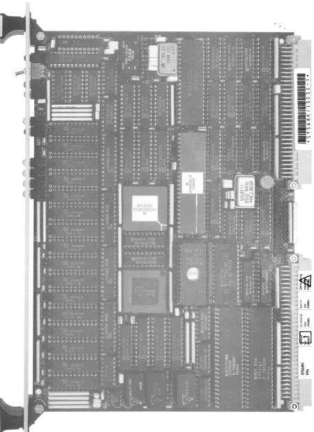
Photo of the SYS68K/ISCSI-l Board ••••••••••••••••• 1-0
Block Diagram of the SYS68K/ISCSI-l ••••••••••••••• 2-0
The Front Panel of the SYS68K/ISCSI-l ••••••••••••• 3-3
Location Diagram of the Jumperfield B19 ••••••••••• 4-5
Photo of the SYS68K/ISCSI-lBPS •••••••••••••••••••• 4-26
SCSI 1.0. Bits . . . 5-1
Sample SCSI Configurations •••••••••••••••••••••••• 5-2
Location of the SCSIbus Terminators ••••••••••••••• 5-5
Location Diagram of the Jumperfield B24 ••••••••••• 5-7
Location Diagram of the Jumperfield B22 ••••••••••• 6-3
Location Diagram of the Jumperfield B2l ••••••••••• 6-5
List of Tables
1.9 General Information
The SYS68K/ISCSI-l is a high performance intelligent SCSlbus
controller board which fully supports the SCSI standard.
Up to 4 floppy drives can be controlled locally, without ,using the
SCSlbus.
The board provides local intelligence with a 68919 CPU, 68459
DMAC, SCSlbus Controller (SCSIBC) and Floppy Disk Controller
(FDC) •
A l28Kbyte Dual Ported RAM (DPR) is used to store data,
and to interface the SYS68K/ISCSI-l board.
Highest throughput is
guaranteed by using a 19MHz 68459 DMAC and the NCR 5386S SCSIBC.
On a single ended SCSlbus, the board works under the powerful
firmware (128Kbyte EPROM area) as initiator or as target.
The SYS68K/SCSI-l's own SCSlbus I.D. is software controlled.
Four floppy drives are fully firmware supported and can also be
accessed via the SCSlbus in the target mode.
The SYS68K/ISCSI-l contains a VMEbus Rev.C/IEEE P19l4 compatible
interface to communicate to the host CPUs via its l28Kbyte DPR.
The access address and the Address Modifier code are jumper
selectable.
A Bus Interrupter Module (BIM 68153) is installed on
the board to support fully asynchronous operation with the 4
different software programmable interrupt request channels.
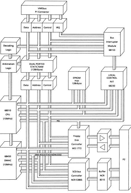
Figure
2-1;
Block Diagram of the SYS68K!ISCSI-l
/
/
VMEbus
PI Connector
V
~L~
Data Address Control IRQ
V
/
/
II
--Bus
/
(]
InterrupterDecoding Module
Logic
V
I II
I II
68153·IL
~
V
ri-V
~/
Arbitration DUAL PORTED
Logic STATIC RAM
/
/
/
/
(128KByte)
V
~
LOCALEPROM CONTROl
max PIIT
Data Address Control 128kByte
V
V
68230r
11
~IL
l.l
II I II
68010 I
-I
I II
CPU 1:::::::=
(10MHz)
I
IR
t-
r-riJJ
/
/
/
/
/
Floppy
[>
Diskr
/l
Controller<J
Ll _111
l i
WD 1772
~
/
I- DMARE E T/A KN WlED E
68450
fd
DMAC
F
r-
r-
/
/
/
/
P2(10MHz) ~ ~ ~
=
t- t- l
-F -F
~r-
r-
SCSI bus BufferController NCR
NCR 5386S 8310
2.8
General Operation
The SYS68K/ISCSI-l is an intelligent VMEbus controller board
providing an SCSlbus interface and a floppy disk interface.
The SYS68K/ISCSI-l board includes 48mA drivers and receivers for
the on-board terminated single ended SCSlbus and SHUGART
compatible floppy interface.
The buffered I/O signals are routed
to the p2 backplane connector.
The NCR 5386S SCSlbus Controller supports the asynchronous and
synchronous data transfer via the SCSlbus.
The WD 1772 floppy disk controller/formatter provides control of a
maximum of four floppy disk drives (3", 3 1/2", 5 1/4").
The 68818 CPU chip, running at 18MHz, executes local software
performing the intelligent I/O functions.
The local I/O devices
can be directly accessed by the CPU.
A 68238 PI/T is installed
for local control and timer functions.
The four channel 68458 Direct Memory Access Controller (DMAC)
controls the high speed I/O data transfer.
The on-board SRAM is a Dual Ported RAM, which is accessible for
the local CPU and DMAC and for the VMEbus master.
The Dual Ported
RAM (DPR) has 128Kbyte of wait-cycle-free memory space for the
local CPU, as well as the medium of interface to the VMEbus
master.
The SYS68K/ISCSI-l board includes the function of an interrupter
to the VMEbus.
Up to four interrupts can be operated independent
from each other.
The SYSFAIL* signal of the VMEbus is supported, and status readout
and a restart call are included in the hardware.
3.B Functional Groups of the SYS68KiISCSI-l
The SYS68K/ISCSI-l consists of the following functional groups:
The 68BlB CPU with ROM
The 68454 DMAC
Local control and decoding
The SCSIbus interface
The floppy disk interface
VMEbus interface and decoding
Dual Ported RAM (DPR)
Bus Interrupter Module with status register
Reset and interrupt trigger call
The watchdog timer
Interrupt generator
The detailed description has been organised in two chapters: the
local CPU hardware is described in Chapter 4 and the VMEbus
interface is described in Chapter 5.
The description of the front panel and the
p2
connector is as
3.1 The Front Panel
The SYS68K/ISCSI-l is delivered with a front panel which also
includes lever handles.
There is a RUN/LOCAL switch with LED indicators
i~
the top
position.
When the switch is down, the board can be accessed on
the VMEbus and the green RUN LED indicates this state.
When the
RUN/LOCAL switch is up, the board cannot be accessed from the
VMEbus.
In this situation the red LED, labelled LOCAL, lights up.
The RUN and LOCAL LEOs can only light up one at a time.
-The bi-colour LED with the label HALT will show a green light
during the normal operation of the local CPU.
It turns to red
when the local CPU is in the HALT state and also during the RESET
of the board.
The yellow LED, labelled SEL for select, lights up each time the
SYS68K/ISCSI-l board is accessed from the VMEbus during data
cycles and interrupt acknowledge cycles of the VMEbus.
The yellow
watch-dog
transfers.
this means
FAIL indicator LED reflects the state of the on-board
timer and blinks during the high-speed DMAC SCSlbus
If the FAIL LED lights up for more that 2 seconds,
that the watch-dog timer has run out of time.
The yellow status LEOs labelled, Sl -
S4, are controlled by the
local PI/T device and are fully software controlled.
These LEOs
are all turned off at the RESET of the board.
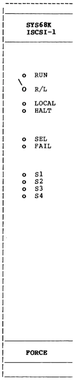
Figure 3-1 shows the front panel of the SYS68K/ISCSI-l with the
switches and LEOs.
3.2 The
1/0
Connector
The VMEbus definition of the Double Eurocard form factor includes
two 96 pin bus connectors.
The PI connector is the primary VMEbus interface.
The p2
connector carries the extension bus signals and power supply
connections via the b row.
Rows a and c are for user I/O signals.
The SYS68K/ISCSI-l board supplies buffered SCSI and floppy disk
interface via the p2 connector.
There are 25 pins providing the
floppy disk I/O signals.
l~
pins of the P2 connector are reserved
for later applications.
Figure 3-1
The Front Panel of the SYS68K/ISCSI-l
SYS68K
ISCSI-l
o
RUN
\
o
R/L
o
LOCAL
o
HALT
o
SEL
o
FAIL
o
Sl
o
S2
o
S3
o
S4
[image:34.547.207.334.50.697.2]4.9 The Local CPU Hardware
There is a 68919 microprocessor clocked at 19MHz working on the
SYS68K/ISCSI-l.
The local CPU chip has an address and data bus totally independent
of the VMEbus".
The local structure includes:
Address decoding
Reset driving
Boot-up support
Interrupt logic
Bus error time-out control
The DMAC (68459)
The EPROMs
The PI/T (68239)
The SCSIbus Controller (5386S)
The FDC (1772)
The read back register for floppy disk control
Access to the Dual Ported RAM
4.1
Implementation of the Local Processor 68919
The local structure is built around the microprocessor 68919 which
is fast enough to control the SCSIbus, the floppy disk interface
and to handle data conversion and transport commands.
The 68919 works at a clock rate of 19MHz, therefore no wait cycles
are needed if the Dual Ported RAM or the EPROM are accessed by the
processor.
This gives maximum yield of the processors power.
The following subchapters describe:
Reset and bootup
Decoding
4.1.1 Reset and Bootup of the Local CPU
The local CPU hardware can be reset in two different ways.
If the SYSRESET* signal of the VMEbus is asserted, then the local
CPU as well as the local peripheral devices and the VMEbus
interface will be reset.
If a byte Read access is performed to the reset trigger address,
then the local CPU and the local peripheral devices will be reset.
The reset trigger address is $1801
+
board base address.-
Default
is: A0l8'H.
For boot-up, upon reset (or restart), the decoding logic is
changed, so that the local EPROMs will be selected instead of the
RAM.
The fir st Wr i te cycle of the local CPU introduces normal
address decoding.
4.1.2 Decoding of the Local Address Space
The local decoding structure is fixed.
follows:
$000000
$C40000
$C80000
$CC0000
$CC0009
$D00000
$E00000
$01FFFF
$C400lF
$C800FF
$CC0007
$CC0009
$D0003F
$E7FFFF
read/write
byte only
read/write
odd byte only
odd byte only
odd byte only
read only
The address map is as
Dual Ported RAM
SCSIbus controller
DMAC
FDC
Control register
PIT
4.1.3 The Local Interrupt Structure
The local interrupt structure is organized as follows:
I
I
V e c t o r
S o u r c e
IRQ Level
I
IRQ Source
I
if B41 inserted
I
if B41 removed
1
2
3
4
5
6
7
P3 Pin #13
DMAC
SCSIBC
FDC
PI/T Timer
PI/T Port
AVI Autovector
DMAC
AV3 Autovector
AV4 Autovector
PI/T Timer
Vector Reg.
PI/T Port
Vector Reg.
Default configuration:
B41 jumper removed.
AVI Autovector
AV2 Autovector
AV3 Autovector
AV4 Autovector
PI/T Timer
Vector Reg.
PI/T Port
Vector Reg.
The PI/T port interrupt can be used under software control to
cause non-maskable (Level 7) interrupts if the watchdog timer
elapses and/or if the VMEbus interrupt trigger call occurs.
4.1.4 The Local Bus Error Structure
4.2
The EPROMs
The SYS68K/ISCSI-l is delivered together with firmware, stored in
two 27128 EPROMs.
These EPROMs must have a maximum access time of
l50ns.
All EPROM access cycles are without wait states.
Other EPROM sizes are configurable by changes in the jumpering at
B19.
The two EPROMs are stacked above each other, the lower byte (bits
0-7) in the lower socket, the upper byte (bits 8-15) in-the upper
socket.
The base address of the EPROMs is $E00000, and only read accesses
are allowed.
The first two long locations in the EPROM pair must contain the
boot-up information as follows:
E00 000 : Initial Supervisor Stack Pointer
E00 004 : Initial Program Counter
Configuration of the B19 jumper area:
2764
9
8--7
4
5--6
3
2-lll
27128
9
8--7
4
5--6
3--2
III
Default
Configuration
27256
9
8--7
4--5
6
3--2
III
27512
9--8
7
4--5
6
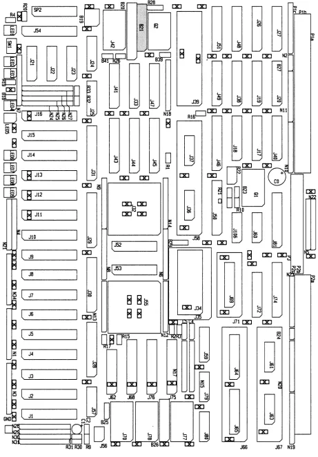
Figure 4-1:
Location Diagram of the Jumperfie1d B19
82i 82B
[Xl~
-
~
~BJi§
(SP2
I
E:l
tl
~
iJ:J
[J
.
-:GQQ~~ ~8
D
IS
----'[Xl
51
8 '--. _ _ _
(
Ji5---I
[1J
('-J_i4 _ _ _ ---IEjl'""""SL....J_iJ _ _
---I[Xlifi
[]J
(,""""SL....J_i2 _ _
---I(8·
JU( JiO
~
('-.19==---_ _
---11
[Xl( J8
('-.16 _ _ _
---11
[Xl~
( .IS
E
-[Xl -[Xl [Xl
[Xl [Xl
lJ52
lJ5J
8 8m
8 8
NiB
8
8
[Xl [Xl [XlJJ9
t... N ,
...
r---1 [Xl [Xl
RiSL...J
[Xl [Xl HU
[Xl
-J7i
[Xl [Xl-4.3 The Parallel Interface and Timer 68239 (PI/T)
There is a PI/T device installed for local control on the
SYS68K/ISCSI-l.
The PI/T can be accessed only by the local CPU.
The address range
is $D9999l to $D9993F - odd byte only.
Table 4-1 gives the address map of the PI/T.
The following subchapters describe
Control of the front panel LEDs
Control of the SYSFAIL* signal and the watchdog timer
Control of the VMEbus interrupt requests
The interrupt trigger input
Reading the RUN/LOCAL switch
Reading the B42 jumper selection
The timer section of the PI/T
The SCSIbus reset control
The single or double floppy density selection
The PI/T port interrupt drives level 7 interrupts and the timer is
connected to drive level
5
interrupts to the CPU.
Both have to be
Table 4-1:
The PI/T Address Map
Base Address : $099999
Address IOffsetl
HEX
I
I
099991
099993
099995
099997
099999
09999B
09999D
D9999F
D99911
D99913
D99915
D99917
D99919
09991B
D99921
D99923
D99925
099927
099929
D9992B
D9992D
D9992F
D99931
D99933
D99935
91
93
95
97
99
9B
9D
9F
11
13
15
17
19
1B
21
23
25
27
29
2B
2D
2F
31
33
35
Reset I
Value I
9F
9F
Label
Description
PITPGCR
Port General Control Register
PITPSRR
Port Service Request Register
PITPADOR
Port A Data Direction Register
PITPBDDR
Port B Data Direction Register
PITPCDDR
Port C Data Direction Register
PITPIVR
Port Interrupt Vector Register
PITPACR
Port A Control Register
PITPBCR
Port B Control Register
PITPADR
PITPBDR
PITPAAR
PITPBAR
PITPCDR
PITPSR
PITTCR
PITTIVR
PITCPR
PITCNTR
PITTSR
Port A Data Register
Port B Data Register
Port A Alternate Register
Port B Alternate Register
Port C Data Register
Port Status Register
Timer Control Register
Timer Interrupt Vector Reg.
ICounter Preload Register
I
I
_I
I ICount Register
I I
I I
I_I
I
4.3.1 Control of the Front Panel LEOs 51-54
There are four yellow LEOs, labelled 51 to 54, installed on the
front panel of the 5Y568K/I5C5I-l, that are driven by the PI/T
device.
These LEOs are fully under control of the local software
which can write Is and 0s to the corresponding PI/T register bits.
LEO
Controlled by
---51
Port B Bit 0
52
Port B
Bit 1
53
Port B Bit 2
54
Port B
Bit 3
For correct operation, Port B has to be programmed to. operate in
the bit I/O mode, and bits 0, 1, 2 and 3 of the Port B data
direction register have to be set (1).
4.3.2 Control of the SYSFAIL* Signal and the Watchdog Timer
There is a watchdog timer installed on the SYS68K/ISCSI-l.
This
is a retriggerable multivibrator with a nominal pulse duration of
29 milliseconds.
This device is included to give information
should a system breakdown occur.
The output state of the watchdog timer is available on the H3
terminal of the
PI/T.
The watchdog timer trigger input is
connected to the PC4 pin of the
PI/T.
The high to low transition
is the trigger.
.
If the watchdog is not triggered for more than 29 milliseconds,
then its output becomes low (9).
Tr igger ing at a rate which is
high enough (i.e. every 19 milliseconds), means that the output of
the watchdog timer can be kept high (1).
In case of a system
breakdown, this retrigger does not occur any more, and the
watchdog timer becomes low (9).
It is possible to use the H3 terminal of the
pI/T not only to
read, but also to use as an interrupt input (level 7 to the CPU).
This gives an option for system recovery as long as the CPU does
not go to HALT.
The SYSFAIL* signal of the VMEbus can be used to broaacast the
fact that a board is not functioning because of boot-up, self test
or failure.
This Signal will not be driven by the ISCSI-l while
SYSRESET* is active.
As soon as SYSRESET* is released, SYSFAIL
will be asserted (driven to low).
This situation can only be
changed by software controlled action of the local CPU.
Two output pins of the
pI/T device control the SYSFAIL* output:
PCl and PC2.
After RESET, both pins are driven high due to
pull-up resistors.
The same is the case with both pins driven high (1)
via software control.
If PCl is programmed to output low logic level (9), then the
SYSFAIL* output to the VMEbus is released.
With PCl
=
low,
SYSFAIL* is never active.
If PCl is high (1), and PC2 is programmed to output low (9), then
the SYSFAIL* output will be asserted if the watchdog timer output
is low (9).
This should be the runtime configuration.
As long as
the periodical toggle at the
pI/T output pin PC4 occurs every 19
milliseconds, the watchdog timer output stays high (1), and
SYSFAIL* will not be asserted by ISCSI-l.
There is one more option:
The watchdog timer output can drive an interrupt request to the
VMEbus via channel 3 of the BIM device.
If pin PCB of the pI/T is
programmed to output low (9), then the watchdog timer output is
connected to set a flip-flop
~o
drive an IRQ to channel 3 of the
4.3.3 Control of the VMEbus Interrupt Requests
There is a Bus Interrupter Module 68153 (BIM) included in the
SYS68K/ISCSI-l.
This device is only accessible from the VMEbus
(see chapter 6.6).
So, the interrupt levels and vectors can only
be programmed by VMEbus masters.
The ISCSI-l local software has
no influence on this.
The local software decides if and on which
channel an inter rupt request (IRQ) will be emitted.
"There are
four channels to output an IRQ, while the BIM can distribute them
to the seven IRQ level lines of the VMEbus.
The interrupt request signal must be released a very short time
after it has been acknowledged.
No software is fast enough to do
that.
Therefore, the IRQ outputs are handled in flip-flops that
are asserted by software via a toggle from the flip-flop clock.
The state of the four IRQ flip-flops can be read back by the local
CPU.
This is absolutely necessary, because a second IRQ can only
be started to the same channel after the first has been
acknowledged.
This affords some dynamic software handling by the local CPU.
An
IRQ asserted can only be cleared by the interrupt acknowledge
cycle or by a SYSRESET* from the VMEbus.
The four IRQ channels are associated and controlled by pins of the
PI/T device as follows:
BIM
Channel
~
1
2
3
VMEbus Default Address
Control
Reg
Address
$A~~~~l
$A~~~~3
$A~~~~5
$A~~~~7
Vector
Reg
Address
$A~~~~9
$A~~~~B
$A~~~~D
$A~~~~F