DOI: 10.4236/ojce.2019.94018 Oct. 17, 2019 255 Open Journal of Civil Engineering
1Wuyi University, Jiangmen, China
2Shanghai Baoye Group Corp., Ltd, Shanghai, China
Abstract
The steel roof of Jiangmen gymnasium is the large-span spatial pipe truss structure, which is composed of main truss, secondary truss and stable truss. This paper systematically expounds the construction simulation analysis, the composition of the construction monitoring system, the monitoring method, and the arrangement of measuring points. The construction simulation anal-ysis simulates the whole process of the main truss cumulative lifting installa-tion, the secondary truss and auxiliary structure hoisting, and then the main truss for overall unloading, which is the difficulty of the whole project. The results of the structural construction monitoring show that the roof structure is in a safe state, and the fine construction simulation analysis provides a theoretical basis for the construction process, and the theoretical value of the simulation analysis is in good agreement with the measured data. In addition, vertical displacement and stress are obvious mutations in the unloading stage of roof support, but the stress of each measuring point is in elastic working condition, which meets the design requirements, indicating the correctness of the model and method in construction simulation analysis and calculation, and also provides reference for the design and construction of related projects in the future.
Keywords
Gymnasium, Pipe Truss, Monitoring, Stress, Displacement
1. Introduction
At present, the large-span spatial steel pipe truss structure is widely used in var-ious large-scale stadiums, theaters, convention and exhibition centers and other important landmarks. It is the embodiment of modern civilization with new materials, new technologies and new techniques as comprehensive technology
How to cite this paper: Chen, K.L., Yuan, G.Q., Wang, L.K., Zhang, W.Z. and Wang, X.K. (2019) Research on Construction Monitoring of Large-Span Steel Pipe Truss Structure. Open Journal of Civil Engineer-ing, 9, 255-267.
https://doi.org/10.4236/ojce.2019.94018
Received: August 28, 2019 Accepted: October 14, 2019 Published: October 17, 2019
Copyright © 2019 by author(s) and Scientific Research Publishing Inc. This work is licensed under the Creative Commons Attribution International License (CC BY 4.0).
DOI: 10.4236/ojce.2019.94018 256 Open Journal of Civil Engineering
plicated forces [3][4]. In order to ensure the safety, applicability and durability of the structure, it is necessary for major engineering structures to carry out structural monitoring during the construction phase [5][6] to ensure the struc-ture with no quality defects. The whole process of construction of the gymna-sium steel roof was simulated and analyzed, and the stress and deformation monitoring were carried out. And the results show that the simulation analysis is in good agreement with the measured data in these papers [7][8], which verifies the correctness of the simulation analysis.
Therefore, real-time monitoring of such large-scale projects and the estab-lishment of sound monitoring system are of great significance for analyzing the structural stress state and ensuring structural safety [9][10][11][12][13]. The structure of the construction monitoring system, construction monitoring me-thod and measuring point layout with a gymnasium as the project background are introduced in this paper. The whole process stress and deformation moni-toring during the construction stage are carried out to ensure the safety of the structure, and an assessment for the safety of the structure during the construc-tion stage will be provided for operaconstruc-tion management. The indicators also pro-vide reference for the design and construction of related projects in the future.
2. Project Overview
The effect picture of Jiangmen Gymnasium is shown in Figure 1. The steel roof structure consists of main truss, secondary truss, stable truss, support, tie rod and peripheral roof are shown in Figure 2. The main truss consists of two rec-tangular trusses that intersect in the north-south direction and the east-west di-rection. The cross-section of the upper and lower chords of the main truss is mainly Φ760 × 16 and Φ560 × 16, and the cross-section of the web is mainly Φ245 × 12 and Φ402 × 16. The stable truss, support and tie rods are arranged in the vertical direction of the secondary truss. The secondary truss is a supporting skeleton for the shape of the stadium roof, which is an east-west plane truss. One end is supported on the surrounding concrete column and the other end is con-nected to the main truss. The cross-section of the upper and lower chords of the secondary truss is mainly Φ245 × 8 and Φ299 × 12, and the main section of the rib is mainly Φ133 × 5. The stable truss support and tie rod members are mainly steel tubes.
3. Construction Technology of the Gymnasium
3.1. Installation and Unloading Plan of Gymnasium RoofDOI: 10.4236/ojce.2019.94018 257 Open Journal of Civil Engineering Figure 1. Effect picture of stadium.
Figure 2. Steel roof of gymnasium.
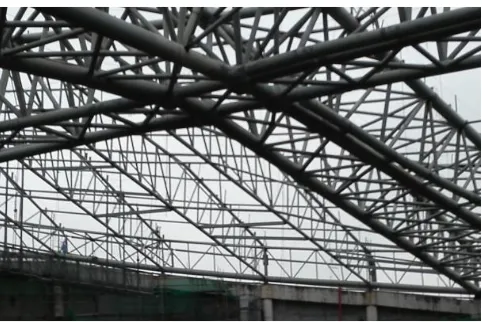
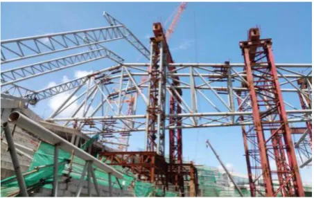
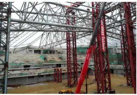
stages, 12 stage will be unloaded and removed the tire frame, and the gantry crane will be unloaded and removal in stage 12, and stable truss and other poles will be installed in 13 to 17 stages. The lifting installation of the main truss structure is shown in Figure 3 and Figure 4, and the hoisting construction of the secondary truss is shown in Figure 5, and the gantry crane unloading is shown in Figure 6.
The steel roof of the gymnasium needs to be unloaded as a whole, and the tonnage of the main truss is about 1200 t. In order to ensure the safety and over-all shape of the structure, it is necessary to control the synchronous decline of each point, in order to ensure that the entire unloading process is implemented according to the plan, and it is combined with the theoretical calculation of the unloading data, and the theoretical unloading result of overall structure and may be different from those of the actual structure. Therefore, the overall unloading theoretically must be calculated accurately to ensure the safety of the unloading conditions.
3.2. Construction Simulation Analysis
[image:3.595.253.494.258.419.2]DOI: 10.4236/ojce.2019.94018 258 Open Journal of Civil Engineering Figure 3. Schematic diagram of main truss lifting.
Figure 4. Main truss lifting.
Figure 5. Secondary truss hoisting construction.
[image:4.595.260.487.467.610.2]DOI: 10.4236/ojce.2019.94018 259 Open Journal of Civil Engineering Figure 6. Remove the tire frame after unloading.
gymnasium is shown in Figure 7, which has a total of 10,653 units with a total of 110 sections, and steel roof model of the gymnasium is shown in Figure 8.
According to the construction characteristics of the roof structure and the re-quirements of construction monitoring and analysis, the method adopted is the step-by-step calculation method, and the simulation calculation of the construc-tion process is carried out by using MIDAS. The so-called dressing calculaconstruc-tion refers to gradually increasing the structural unit and changing the construction load according to the predetermined construction sequence and process flow, calculating the stress on the deformation, internal force and dangerous section of the structure at each construction stage, and obtaining the internal force state of the whole construction process.
Figure 9 to Figure 10 are respectively the stress cloud diagram and the vertic-al displacement cloud diagram in the unloading stage. The cvertic-alculation results show that the maximum unloading stress is 196.8 MPa, which is at the lifting point of the upper main truss, and the stress value of most rods is between 30 MPa and 70 MPa, and the maximum vertical displacement is 13.9 cm, and the theoretical calculation result shows that there is a significant mutation at this stage.
3.3. Construction Monitoring System
DOI: 10.4236/ojce.2019.94018 260 Open Journal of Civil Engineering Figure 7. Overall model of the gymnasium.
Figure 8. Steel roof model of the gymnasium.
[image:6.595.214.535.493.693.2]DOI: 10.4236/ojce.2019.94018 261 Open Journal of Civil Engineering Figure 10. Main truss stress during unloading stage (Unit: Pa).
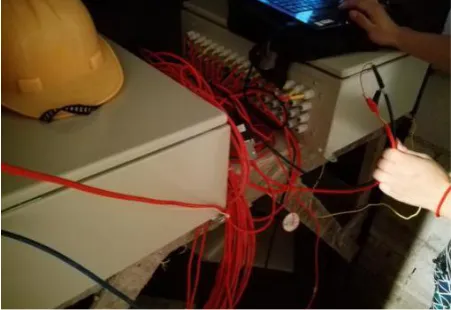
Figure 11. Strain acquisition system.
This project adopts vibrating wire strain system, and arranges vibrating wire strain sensors in key parts of the structure. As shown in Figure 12, 1 to 6 sec-tions are arranged on the main truss, and each section has 8 strain sensors. The strain sensor wires are processed into two bundles as shown Figure 13, so that there is no wire chaos or wire tie or even wire breakage during the main truss jacking process, ensuring the accuracy of data acquisition.
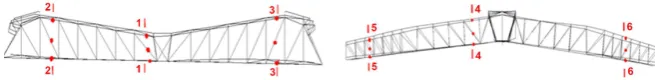
[image:7.595.260.486.314.469.2]DOI: 10.4236/ojce.2019.94018 262 Open Journal of Civil Engineering Figure 12. The arrangement of stress point.
Figure 13. Strain sensor wire.
Figure 14. The displacement point of main truss.
4. Analysis of Construction Monitoring Results
[image:8.595.264.475.334.532.2]DOI: 10.4236/ojce.2019.94018 263 Open Journal of Civil Engineering Figure 15. Monitoring site photos.
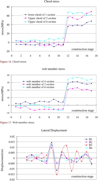
It can be seen from Figure 16 to Figure 17 that there are three stress measur-ing points of the chord, which are the lower chord of No.1 section, the upper chord stress curves of No.2 and No.6, and the stress curve of the measuring point does not change significantly before unloading, and the stress change is in the range of −10 MPa to 10 MPa, and the internal force variation of the chord measuring points of the three sections is basically similar. During the unloading of the 12 stage tire frame, the stress value suddenly increased sharply, and the increased stress value is about 40 MPa to 60 MPa. The law of stress change on web member is similar to that of the chord. Under the unloading condition, the stress of the web member is suddenly increased. The measuring points have the same variation law and stress abrupt value, but far less than the yield strength of the steel (345 MPa). After the stage of unloading, the internal force of the rod gradually shifts and the internal force redistribution occurs. The law of stress change is greatly affected by factors such as time and weather, and the stress of the bars is increased or decreased, but the overall change is little.
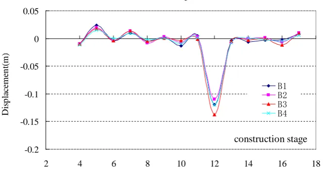
It can be concluded from Figure 18 to Figure 19 that the lateral deformation in the Y direction changes disorderly with the development of the construction stage. Even in the unloading stage, there is no obvious law in the Y direction displacement, and the X direction displacement variation law is similar to the Y direction. From the vertical deformation diagram, it can be seen that in the un-loading stage, there is a large abrupt change in the vertical deformation, and the maximum value of the vertical deformation is 13.2 cm, while the vertical defor-mation in other construction stages is small, which shows that the main truss bears a large load during the unloading stage. The vertical displacement abrupt stage of the main truss coincides with stress abrupt stage of the main truss, and the vertical deformation of the structure, and the vertical deformation of the structure after unloading changes little.
DOI: 10.4236/ojce.2019.94018 264 Open Journal of Civil Engineering Figure 16. Chord stress.
Figure 17. Web member stress.
Figure 18. Lateral displacement. -20 0 20 40 60 80
0 2 4 6 8 10 12 14 16 18
construction stage st re ss( M P a)
lower chord of 1 section Upper chord of 2 section Upper chord of 6 section
web member stress
-10 0 10 20 30 40
0 2 4 6 8 10 12 14 16 18
construction stage st re ss( M P a)
web member of 4 section web member of 3 section web member of 6 section
Lateral Displacement -0.02 -0.015 -0.01 -0.005 0 0.005 0.01 0.015 0.02
2 4 6 8 10 12 14 16 18
[image:10.595.209.537.88.273.2]DOI: 10.4236/ojce.2019.94018 265 Open Journal of Civil Engineering Figure 19. Vertical displacement.
Table 1. Comparison of stress values during unloading.
Serial
number position
Construction stress Change in stress
②-①
Theoretical
value of stress Stress measured value and rationality Value comparison
②/ ③
Stage 11 ① Stage 12 ② Stage 12 ③
MPa MPa MPa MPa
Section 1
LC1 −4.4 35.64 40.04 48 0.74
LC1 −10.66 37.2 47.86 48 0.78
LC2 −17.6 46.14 63.74 48 0.96
LC2 −7.24 48.08 55.32 48 1.00
Section 2
LC1 −9.06 16.6 25.66 55 0.30
LC1 −12.76 29.1 41.86 55 0.53
LC2 −6.3 55.82 62.12 55 1.01
LC2 −12.6 44.34 56.94 55 0.81
Section 3
LC1 −-15 47.26 62.26 55 0.86
LC1 −5.02 50.8 55.82 55 0.92
LC2 −8.94 46.64 55.58 55 0.85
LC2 10.9 60.72 49.82 55 1.10
each lower chord,and the arrangement of the sensors is symmetrical about the axis of the rod. As shown in Table 1, the stress values in the unloading stage have large mutations, and the variation value is generally about 40 to 60 MPa, but the variation value of some strain sensors is less than 30 MPa. There is also an error in the value of the measured stress at the same position of the same rod, but the error is on the whole within 10 MPa. Moreover, the ratio of the meas-ured stress value of most rods to the theoretical value is about 0.7 to 1.1, and the ratio is between a reasonable range, but there are also some points where the ra-tio is not in this range because of temperature or environmental impact.
-0.2
2 4 6 8 10 12 14 16 18
[image:11.595.209.539.308.573.2]DOI: 10.4236/ojce.2019.94018 266 Open Journal of Civil Engineering
the measured results are basically consistent with the theoretical results, which fully demonstrates the correctness of theoretical analysis.
5. Conclusions
In this paper, the stress and displacement monitoring system is used to monitor the stress and displacement of key members in the construction stage of Jiang-men gymnasium, and the following conclusions are drawn.
1) Through real-time monitoring of the whole process of the stadium con-struction stage, the results show that the maximum stress of the steel structural members is within the reasonable design range, and the stress in the unloading stage is obviously abrupt, but the internal force of the rod is much smaller than the yield strength of the material. The stress state of the point is always in the elastic working state, and the entire structure is safe to meet the design require-ments.
2) The lateral displacement of the measuring points in each construction stage changes disorderly. The vertical displacement of the measuring points is basical-ly the same. Before the unloading stage and after the unloading stage, the vertical displacement changes are relatively stable, and the vertical displacement of the unloading stage is about obvious mutation, which is basically consistent with the actual calculated value, indicating that the structural stiffness meets the design requirements.
3) Through the analysis results of monitoring the steel structure construction in the gymnasium, the selection of the monitoring system of this project is rea-sonable, and the selection of key points and key parts is effective, which is of great significance for analyzing the structural stress state and ensuring the structural construction safety. The monitoring methods, measuring point ar-rangements and methods in this paper can provide reference for similar engi-neering structures.
Acknowledgements
The paper is supported by the Special Funds of the National Natural Science Foundation of China (11502172) and Guangdong Science and Technology De-partment Project (2016A040403125).
Conflicts of Interest
The authors declare no conflicts of interest regarding the publication of this paper.
References
[1] Dong, S.L., Xing, D. and Zhao, Y. (2012) Application and Development of Modern Long-Span Space Structures in China. Spatial Structures, 18, 3-16.
DOI: 10.4236/ojce.2019.94018 267 Open Journal of Civil Engineering 30, 127-153.
[7] Wang, X.L., Rong, Z.H., Yang, B.X., Luo, C.D., Zhou, Y. and Wu, X.Y. (2017) Whole Process Simulation Analysis and Health Monitoring of Spatial Pipe Truss Structure Gymnasinm. Journal of Architecture and Civil engineering, 34, 18-25. [8] Qian, J.R. Zhang, W.J., Zhao, Z.Z., Pan, P., Zhong, C.L. and Jiang, Q.Z. (2009)
Si-mulation and Monitoring for the Construction of the Steel Roof of the Peking Uni-versity Gymnasium. China Civil Engineer Journal, 42, 13-20.
[9] Patrikar, A. and Pathak, K. (2016) Fully Stressed Design of Fink Truss Using STAAD. Pro Software. Open Journal of Civil Engineering, 6, 631-642.
https://doi.org/10.4236/ojce.2016.64051
[10] Mesda, Y. (2013) Analytical Study of the Cable-Truss Systems on the Glass Certain Walls with Vertical Uses. Engineering, 5, 819-826.
https://doi.org/10.4236/eng.2013.510099
[11] N YQ, Jian, S.F. and Ko, J.M. (2001) Application of Adaptive Probabilistic Neural Network to Damage Detection of Tsing Ma Bridge. Health Monitoring and Man-agement of Civil Infrastrutures Systems, SPIE, USA, Vol. 4337, 347-356.
https://doi.org/10.1117/12.435610
[12] Farrar, C.R., Duffey, T.A., Doebling, S.W., et al. (1999) A Statistical Pattern Recog-nition Paradigm for Vibration-Based Structural Health Monitoring. The 2nd Inter-national Workshop on Structural Health Monitoring, Stanford, CA, 245-257 [13] Zhou, G.G., Chen, X., Wang, Y.M., et al. (2010). Key Construction Technology for