eversal
AZIM, Zubair Al, OSTLER, Thomas <http://orcid.org/0000-0002-1328-1839>,
XU, Chudong and ROY, Kaushik
Available from Sheffield Hallam University Research Archive (SHURA) at:
http://shura.shu.ac.uk/22985/
This document is the author deposited version. You are advised to consult the
publisher's version if you wish to cite from it.
Published version
AZIM, Zubair Al, OSTLER, Thomas, XU, Chudong and ROY, Kaushik (2019). Optical
receiver with helicity-dependent magnetization eversal. IEEE transactions on
magnetics, 55 (1).
Copyright and re-use policy
See
http://shura.shu.ac.uk/information.html
Optical Receiver with Helicity Dependent Magnetization Reversal
Zubair Al Azim
1, Thomas A. Ostler
2,3, Chudong Xu
4, and Kaushik Roy
1,
Fellow, IEEE
1School of Electrical and Computer Engineering, Purdue University, West Lafayette, IN 47907, USA
2Faculty of Arts, Computing, Engineering and Sciences, Sheffield Hallam University, Howard Street, Sheffield, S1 1WB, UK 3
Nanomat / Q-MAT / CESAM and European Theoretical Spectroscopy Facility, Universitè de Liège, B-4000 Liège, Belgium
4College of Electronic Engineering, South China Agricultural University, Guangzhou, Guangdong 510642, China
In this work, we propose helicity-dependent switching (HDS) of magnetization in Co/Pt for an energy efficient optical receiver. Designing a low power optical receiver for optical-to-electrical signal conversion has proven to be very challenging. Current day optical receivers use a photodiode that produces a photocurrent in response to input optical signals, and power hungry trans-impedance amplifiers are required to amplify the small photocurrents. These limitations can be overcome by using light helicity induced switching of magnetization which can avoid the requirement of photodiodes and subsequent trans-impedance amplification by sensing the change in magnetization with a magnetic tunnel junction (MTJ). Magnetization switching of a thin ferromagnet layer using circularly polarized laser pulses have recently been demonstrated which shows one-to-one correspondence between light helicity and the magnetization state. We use this phenomena to directly switch the magnetization state of a thin Co/Pt ferromagnet layer at the receiver via circularly polarized laser pulses. The circular polarization is controlled in accordance to digital input data which establishes a one-to-one correspondence between the transmitted data and output magnetization state. The Co/Pt layer is used as the free layer of an MTJ, the resistance of which is modified by the laser pulses. Since the output magnetization state is controlled by the input data, the MTJ resistance is directly converted to digital output signal. Our device to circuit level simulation results indicate that, HDS based optical receiver circuit consumes only 𝟎. 𝟏𝟐𝟒 pJ/bit energy, which is much lower than existing techniques.
Index Terms—Laser induced magnetization reversal, magnetic tunnel junction, magnetization dynamics, optical interconnect.
I. INTRODUCTION
PTICAL INTERCONNECT is considered to be the leading candidate for off-chip communication in future multi-core systems due to its negligible channel loss and higher noise immunity [1, 2]. However, in order to broaden its commercial application, optical interconnects must offer orders of magnitude higher energy efficiency compared to existing electrical interconnects [3]. Significant progress has been made in recent years to lower the energy consumption in optical interconnects, especially in the conversion of electrical to optical signals [1]. Designing highly energy efficient receivers for optical-to-electrical signal conversion, however, remains a challenge. Present-day optical receivers need to convert small photocurrents to CMOS (complementary metal-oxide semiconductor) compatible voltage signals, which leads to several design challenges [3]. The direct use of optical signals to induce switching of magnetization can potentially overcome some of these challenges.
Magnetization reversal using only ultrafast laser pulses has recently been demonstrated in several experiments [4, 5] and remains a topic of great interest. In addition, the demonstration of an optically switchable free layer in a magnetic tunnel junction (MTJ) has shown the possibility of using laser induced magnetization reversal for circuit operations [6, 7]. The process of laser induced magnetization switching can either be dependent or independent of the laser pulse helicity/polarization [4, 5]. Laser helicity dependent switching (HDS) is more desirable for the conversion of optical-to-electrical signal because of the inherent one-to-one correspondence between the optical signal and magnetization
state. The reversal of magnetization through single-shot laser pulses has been shown to be helicity independent and a purely thermal process, which is observed mostly in ferrimagnets [5]. Although, single-shot switching was recently observed in ferromagnetic Pt/Co/Pt multilayer structures [8], the switching was shown to be helicity-independent and the time-scale of the process was on the order of nanoseconds. Exchange coupled ferromagnetic/ferrimagnetic ((Co/Pt)/GdFeCo) multilayers were also shown [9] to exhibit ultrafast switching (within 7 ps); however, no helicity-dependence was shown. HDS was previously found to occur through the action of multiple laser pulses, though again, mostly in ferrimagnetic materials [4]. The necessity of using exotic ferrimagnetic materials is undesirable for the conversion of optical-to-electrical signal.
In this work, we propose helicity-dependent switching of magnetization in a thin Co/Pt ferromagnet layer for an energy efficient optical receiver. The helicity-dependent switching process in ferromagnets has recently been demonstrated experimentally in [10-13]. Laser pulses with right-hand circular polarization (RHCP or 𝜎 +) were shown to the reverse magnetization from a ‘down’ to an ‘up’ state and vice-versa. With the use of HDS, it becomes possible to have one-to-one correspondence between input data and output magnetization state. This can be achieved by transmitting laser pulses with opposite circular polarization (either right-hand or left-hand) for digital ‘0’ or ‘1’ input data. We should point out that multiple pulses are needed to switch the ferromagnet layer as shown in [10-13]. In order to effectively use HDS for circuit application, the Co/Pt layer can be used as the free layer of an MTJ. Laser pulses modify the MTJ resistance in accordance to the helicity and this resistance change can be sensed through a resistive divider action. In essence, the integration of Co/Pt layer with an MTJ enables digital circuit application of HDS in a ferromagnet.
O
We will first present the modeling of HDS in ferromagnets using the Landau-Lifshitz-Bloch (LLB) formalism. The model is developed in-house and is outlined in [14-16]. Next, we will discuss how we incorporate the magnetization dynamics with an MTJ resistance model in order to perform device to circuit level simulation. We will conclude by presenting the details of our proposed optical receiver and evaluating its performance.
II. MODELING OF HDS IN FERROMAGNETS AND INCORPORATING WITH CIRCUIT SIMULATION
A. Modeling of HDS in Ferromagnets Using Landau-Lifshitz-Bloch (LLB) Formalism
The LLB equation describes the time evolution of a magnetic macrospin. The equation allows for longitudinal relaxation (as well as transverse precessional and relaxation behavior) of the magnetization, and was derived by Garanin [17] within a mean field approximation from the classical Fokker-Planck equation for atomic spins interacting with a heat bath. In this sense, the equation attempts to describe, in a spatially averaged way, the motion of an ensemble of magnetic moments. Models based on the resulting expressions have been shown to be consistent with atomistic spin dynamics simulation [18], as well as comparisons with experimental observations, for example, in laser induced demagnetization [19]. The equation is similar to the Landau-Lifshitz-Gilbert (LLG) equation [20], with precessional and relaxation terms, but with an extra term that deals with changes in the length of the magnetization:
𝑑𝑚⃗⃗
𝑑𝑡 = − 𝛾(𝑚⃗⃗ × 𝐻⃗⃗ 𝑒𝑓𝑓) +
𝛾𝛼‖
𝑚2(𝑚⃗⃗ . 𝐻⃗⃗ 𝑒𝑓𝑓)𝑚⃗⃗
− 𝛾𝛼⊥
𝑚2 (𝑚⃗⃗ × (𝑚⃗⃗ × 𝐻⃗⃗ 𝑒𝑓𝑓))
(1)
where 𝑚⃗⃗ is the spin polarization, 𝑀⃗⃗ 𝑀⁄ 𝑠(0). The spin
polarization tends towards equilibrium, 𝑚⃗⃗⃗⃗⃗ 𝑒, which is a
temperature dependent quantity. 𝛼‖ and 𝛼⊥ are dimensionless
longitudinal and transverse damping parameters, respectively.
𝛾 is the gyromagnetic ratio taken to be the free electron value. The LLB equation is valid for finite temperatures and even above Curie temperature (𝑇𝐶) though the damping parameters
and effective fields are different below and above 𝑇𝐶. For the transverse damping parameter:
𝛼⊥=
{
𝜆 (1 − 𝑇
𝑇𝐶) , 𝑇 < 𝑇𝐶
𝜆2𝑇
3𝑇𝐶, 𝑇 ≥ 𝑇𝐶
(2)
and for the longitudinal:
𝛼‖= 𝜆
2𝑇
3𝑇𝐶, for all 𝑇
(3)
For a single particle, the effective field 𝐻⃗⃗ 𝑒𝑓𝑓 is given by [17]:
TABLE I
PHYSICAL PARAMETERS USED IN THE LLB MODEL FOR CO/PT
Parameters Value used Heat bath coupling parameter, λ 0.025
Saturation magnetization, 𝑀𝑠(0) 1.438 × 10⁶JT-1m-3
Gyromagnetic ratio, 𝛾 1.76 × 10⁻¹¹T-1s-1 System size 100 × 100nm2
Number of macrospins 50 × 50 × 1 Macrospin size 2 × 2 × 0.6nm3
Curie temperature, 𝑇𝐶 650 K
Laser fluence 1.5 × 10²⁰ W/m3
𝐻⃗⃗ 𝑒𝑓𝑓= 𝐵⃗ + 𝐻⃗⃗ 𝐴+
1
2𝜒̃ (1 −‖
𝑚2
𝑚𝑒2) 𝑚⃗⃗ + 𝐻⃗⃗ 𝑒+ 𝐻⃗⃗ 𝑑𝑒𝑚𝑎𝑔
(4)
where 𝐵⃗ represents an external magnetic field, 𝐻⃗⃗ 𝐴 is the uniaxial easy axis anisotropy field and 𝐻⃗⃗ 𝑒 is the exchange
field. 𝜒̃‖ is the parallel susceptibility which is defined by
𝜒‖
̃ = 𝜕𝑚‖⁄𝜕𝐻‖. The final term, 𝐻⃗⃗ 𝑑𝑒𝑚𝑎𝑔 is the demagnetizing
field. In the above equations, 𝜆 is a microscopic parameter which characterizes the coupling of the individual, atomistic spins with the heat bath. We choose the value of 𝜆 to be
0.025, however, the demagnetization process is strongly
dependent on this parameter. Table I shows a summary of the parameters that are used in our model.
To account for the laser heating in this model, we utilize the semi-classical two-temperature model [21, 22] of laser heating. This model defines a temperature associated with the electron and phonon heat baths through the simplified equations:
𝐶𝑒
𝜕𝑇𝑒(𝑥, 𝑦)
𝜕𝑡 = −𝐺(𝑇𝑒(𝑥, 𝑦) − 𝑇𝑙(𝑥, 𝑦)) + 𝑃(𝑥, 𝑦, 𝑡) (5)
𝐶𝑙
𝜕𝑇𝑙(𝑥, 𝑦)
𝜕𝑡 = 𝐺(𝑇𝑒(𝑥, 𝑦) − 𝑇𝑙(𝑥, 𝑦)) +
𝑇𝑙(𝑥, 𝑦) − 𝑇𝑒𝑞
𝜏𝐶
(6)
where 𝐶𝑒, 𝑇𝑒 and 𝐶𝑙, 𝑇𝑙 are the electron and lattice specific heats and temperatures, respectively, and 𝐺 is the electron-lattice coupling constant. 𝑇𝑒𝑞 is the equilibrium temperature
set to 300 𝐾 and 𝜏𝐶 is the cooling time, which we assume to
be 100 𝑝𝑠. The time-and-spatially dependent laser power is
assumed to be Gaussian in both time and space:
𝑃(𝑥, 𝑦, 𝑡) = Ƒ exp (− (𝑡 − 𝑡0
𝜏𝑃 )
2
)
× exp (−(𝑥 − 𝑥0)
2
2𝜎𝑥2 ) exp (−
(𝑦 − 𝑦0)2
2𝜎𝑦2 )
(7)
where 𝑡0 is the pump delay, 𝜏𝑃 is the pump width which we
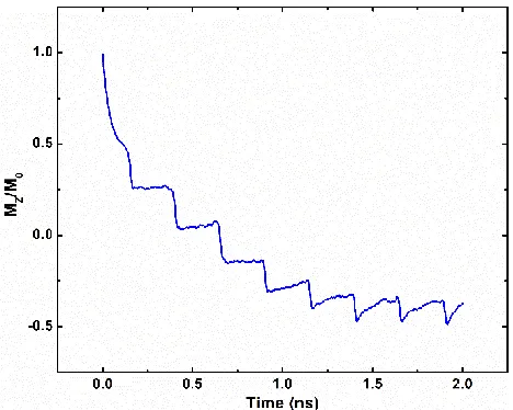
Fig. 1. Temporal response of a thin Co/Pt layer magnetization in response to successive LHCP (𝜎 −) laser pulses.
𝜎𝑦 are the spatial widths in 𝑥 and 𝑦 directions, respectively,
which are set to 50 𝜇𝑚. This is a typical width of a femtosecond laser experiment, which essentially provides uniform heating to our element. As well as implementing the spatial dependence of the pump fluence, we have also added a spatial dependence of the field intensity arising from the inverse Faraday effect in a phenomenological way (IFE, which signifies the generation of a magnetic field according to light polarization [23]). The width of the IFE field temporally was chosen to be 9.5 𝑝𝑠. The field amplitude from IFE was chosen to be 5 𝑇, the sign of which was altered in accordance with laser helicity. Considering the relatively short duration of the laser pulse, a temporal width of 9.5 𝑝𝑠 is rather long given that the optical coherence time in metals should be comparable to the pulse duration. However, similar demagnetization times and degree of demagnetization/switching was observed experimentally in [10, 11] and investigated theoretically in [24]. Furthermore, the amplitude of the field is somewhat difficult to quantify. In the theory of the IFE, the effect of the light is to induce a magnetization. Here, we assume that a phenomenological field gives rise to this change in magnetization, though this approximation has been used to good effect in previous works [25] and remains an interesting and open question [26]. Helicity dependent switching in ferromagnet occurs through the action of multiple laser pulses to allow sufficient time for transfer of angular momentum from the laser to the magnet [10-13]. In our model, we allow
250 𝑝𝑠 time interval between successive laser pulses such that
[image:4.612.57.291.48.235.2]heating due to laser pulses do not randomize the magnetization. The values of IFE field width and duration as well as the successive pulse separation interval were chosen to roughly approximate the number of laser pulses required to induce switching in [10, 11]. The size of our elements (given in Table I) are much smaller than those in the experiments of [10, 11]. Hence, our switching is completed (to saturation) faster than in experiments, as the effect from the demagnetizing field is much smaller. As our focus here is not to understand the origins of all-optical switching but pose a potential application of the phenomena, a complete one-to-one agreement of the theory and experiment is not necessary.
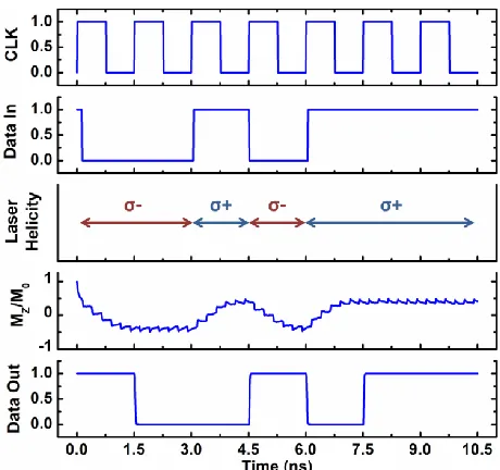
Fig. 2. Temporal response of a thin Co/Pt layer magnetization in response to both LHCP (𝜎 −) and RHCP (𝜎 +) laser pulses.
In Fig. 1, we show the temporal variation of Co/Pt layer magnetization in response to left-hand circularly polarized (LHCP or 𝜎 −) laser pulses. The initial magnetization was taken to be pointing in the ‘up’ direction (𝑀𝑍⁄𝑀0≈ +1). The
number of pulses required to reverse the magnetization is 6 and the reversal takes ~1.4 𝑛𝑠 as shown in Fig. 1. Note that the degree of reversal is limited (𝑀𝑍⁄𝑀0 saturates to ~ − 0.5
in Fig. 1) because of the fact that the equilibrium (operating) temperature is kept fixed at room temperature. The temporal magnetization response to multiple helicity laser pulses is shown in Fig. 2. Starting again from an initially ‘up’ magnetized state, the magnetization reverses in ~1.4 𝑛𝑠 in response to 𝜎 − pulses. We continue to apply 𝜎 − pulses up to
3 𝑛𝑠. However, once the magnetization saturates, further application of 𝜎 − pulses do not change the magnetization. After 3 𝑛𝑠, the laser helicity is reversed to 𝜎 +. The application of 𝜎 + pulses again reverses the magnetization towards ‘up’ state as shown in Fig. 2. This demonstrates the possibility of repeated operation by altering the laser helicity, which is necessary for the interconnect application.
B. Incorporating HDS with an MTJ for Circuit Analysis
In order to use HDS for circuit application, a thin Co/Pt layer is used as the free layer of an MTJ as shown in Fig. 3. The resistance of this MTJ is tuned by the laser helicity-induced magnetization control of the Co/Pt layer. With the direction of the MTJ pinned layer shown in Fig. 3, the MTJ resistance is high (𝑅𝐴𝑃) when the Co/Pt magnetization is close to the ‘down’ state and MTJ resistance is low (𝑅𝑃) when the
Co/Pt magnetization is close to the ‘up’ state. The resistance of the MTJ stack is modeled by non-equilibrium Green's Function (NEGF) formalism and abstracted into a behavioral MTJ resistance model. A detailed description of this method can be found in [27]. The laser induced magnetization data is incorporated with this behavioral MTJ resistance model to evaluate the laser helicity induced MTJ resistance change. The resistance of the MTJ is then subsequently integrated with
IBM 45 𝑛𝑚 CMOS technology to evaluate the circuit
Fig. 3. Co/Pt as the free layer of an MTJ, the resistance of which can be tuned by using circularly polarized laser pulses.
One important issue to consider in our device operation is the likelihood of laser induced demagnetization on the pinned layer. This is due to the possibility that laser pulses can enter the pinned layer through the tunneling oxide layer. However, the pinned layer is usually a much thicker ferromagnet layer than the free layer. In addition, the magnetization of the pinned layer is stabilized by using an anti-ferromagnet layer and a synthetic anti-ferromagnet layer adjacent to the pinned layer [28]. The presence of such layers makes the magnetization of the pinned layer much less susceptible to external perturbation from the laser pulses. Moreover, the laser pulses need to penetrate the tunneling oxide in the MTJ before reaching the pinned layer, which makes the impact even lower. In fact, laser induced switching in a magnetoresistive device have been demonstrated experimentally in [7], where the impact of the laser pulse demagnetization on the pinned layer was negligible. We next present the receiver circuit operation.
III. OPTICAL RECEIVER OPERATION USING HDS The schematic of the optical interconnect circuit using HDS at the receiver is shown in Fig. 4. As mentioned previously, the Co/Pt ferromagnet layer is used as the free layer of an MTJ at the receiver. The magnetization state of this Co/Pt layer is modified by using circularly polarized laser pulses. The change of the MTJ resistance is sensed by using the reference MTJ as shown in Fig. 4, which creates a resistance divider network. A read current is passed through the two MTJ resistances (connected in series) by using the terminal 𝑉Read. The read current sets the voltage at node ‘M’
in Fig. 4 in accordance to the resistance of the bottom MTJ. This resistive divider MTJ network drives a clocked CMOS inverter as shown in Fig. 4 to produce the appropriate digital output signal. A digital input data controls the laser polarization through the use of a binary circular polarization modulator [29] at the input side. The optical modulator controls the helicity of the laser input from an off-chip laser source and transmits the resultant circularly polarized laser pulses through an optical medium. We assume 𝜎 − pulses are transmitted for digital input ‘0’ and 𝜎 + pulses for input ‘1’.
We show a sample operation in Fig. 5. Here, continuous operation is shown for 7 clock cycles with a random data input
[image:5.612.357.524.50.223.2]of ‘0010111’. We used 1.5 𝑛𝑠 as the clock period to allow
Fig. 4. Schematic of the optical interconnect scheme with HDS based receiver.
Fig. 5. Continuous operation of the interconnect circuit with a random input sequence.
sufficient time for helicity induced magnetization reversal. We assume that the magnetization state of the Co/Pt free layer is initially pointing in the ‘up’ direction (𝑀𝑍⁄𝑀0≈ +1). In the
first clock cycle, the input data is ‘0’, which results in the transmission of 𝜎 − pulses from the modulator. Since the free layer magnetization is initially in the ‘up’ direction, the 𝜎 −
[image:5.612.57.282.52.203.2] [image:5.612.325.555.254.470.2]IV. PERFORMANCE EVALUATION
The key feature of the proposed method is that the operation is simple which leads to an energy efficient performance. The energy dissipation at the receiver circuitry to read the magnetic state is the major component (~10 × higher than the required energy to reverse the magnetization) of the overall receiver energy. Hence, we calculate the dissipated energy at the receiver circuitry and compare with existing designs. To estimate the energy dissipation at the receiver, we perform a SPICE based circuit simulation. The dissipated energy in the circuit is calculated by measuring the supply source current and averaged over varying input data pattern. We find that the average dissipated energy at the receiver circuit is 0.124 pJ/bit. This is ~4 × lower than the required energy dissipation in the receiver circuit using laser heat induced reversal in a ferrimagnetic GdFeCo based MTJ [30]. The energy consumption is also ~5 × lower than the advanced Ge photodiode based receivers shown in [31] and [32], which were reported to be the lowest among photodiode based receivers. The key limitation of our proposal, however, is the operating speed. This is because, magnetization reversal in ferromagnets through HDS is dictated by the cumulative action from multiple laser pulses [10-13]. This is the major contrast in comparison with single-shot laser heat induced switching, where a single pulse can induce switching through ultrafast heating [5]. Hence, laser heat induced magnetization reversal in ferrimagnets is significantly faster than HDS in ferromagnets (~5 × faster). However, optical receivers using laser heat induced magnetization reversal require the use of extra memory elements since there is no one-to-one correspondence between the laser pulse and magnetization state, which leads to the higher energy consumption. Moreover, as mentioned previously, laser heat induced magnetization reversal process applies primarily to ferrimagnets. Hence, the receiver in [30] requires the integration of ferrimagnet based MTJs, which creates additional design challenges. Our proposal only requires ferromagnetic MTJs, which is more desirable from a technology integration point of view. In spite of the slower operating speed, the proposed technique can be highly beneficial in situations where data needs to be transmitted over a very long distance at the lowest possible energy overhead with relaxed latency.
V. CONCLUSION
To conclude, we have proposed helicity dependent switching of ferromagnets as an energy efficient process for optical-to-electrical signal conversion in optical interconnects. We developed a physics based model for HDS in ferromagnets and applied the model to develop a device to circuit level simulation framework. Our proposal shows the possibility of applying HDS to perform low power circuit operations.
ACKNOWLEDGMENT
This research was funded in part by C-SPIN, the center for spintronic materials, interfaces, and architecture, funded by DARPA and MARCO; the Semiconductor Research Corporation, the National Science Foundation, and the
Vannevar Bush Faculty Fellows program. T. A. Ostler gratefully acknowledges the support of the Marie Curie incoming BeIPD-COFUND fellowship program at the University of Liège. C. Xu would like to acknowledge the support of the Natural Science Foundation of Guangdong China (Grants No. 2015A030313400 and No. 2017A030313009) and the Guangzhou Scientific Research Project (Grants No. 201707010347).
REFERENCES
[1] A. Biberman and K. Bergman, “Optical interconnection networks for high-performance computing systems,” Reports on Progress in Physics, vol. 75, issue 4, p. 046402, 2012.
[2] S. Mishra, N. K. Chaudhary, and K. Singh, “Overview of Optical Interconnect Technology,” International Journal of Scientific & Engineering Research, vol. 3, issue 4, 2012.
[3] A. V. Krishnamoorthy et al., “Progress in Low-Power Switched Optical Interconnects,” IEEE Journal of Selected Topics in Quantum Electronics, vol. 17, no. 2, pp. 357-376, 2011.
[4] C. D. Stanciu, F. Hansteen, A. V. Kimel, A. Kirilyuk, A. Tsukamoto, A. Itoh, and T. Rasing, “All-optical magnetic recording with circularly polarized light,” Physical Review Letters, vol. 99, p. 047601, 2007. [5] I. Radu et al., “Transient ferromagnetic-like state mediating ultrafast
reversal of antiferromagnetically coupled spins,” Nature, vol. 472, pp. 205-208, 2011.
[6] M. Li and J.-P. Wang, “Optical interconnect in spin-based computation and communication systems,” U.S. Patent 14/279 990, May 16, 2014. [7] L. He, J.-Y. Chen, J.-P. Wang, and M. Li, “All-optical switching of
magnetoresistive devices using telecom-band femtosecond laser,”
Applied Physics Letters, vol. 107, p. 102402, 2015.
[8] M. Vomir, M. Albrecht, and J.-Y. Bigot (2017), “Single shot all optical switching of intrinsic micron size magnetic domains of a Pt/Co/Pt ferromagnetic stack,” [Online]. Available:
https://arxiv.org/abs/1710.10341.
[9] J. Gorchon, C.-H. Lambert, Y. Yang, A. Pattabi, R. B. Wilson, S. Salahuddin, and J. Bokor, “Single shot ultrafast all optical magnetization switching of ferromagnetic Co/Pt multilayers,” Applied Physics Letters, vol. 111, p. 042401, 2017.
[10] C.-H. Lambert, S. Mangin, B. S. D. C. S. Varaprasad, Y. K. Takahashi, M. Hehn, M. Cinchetti, G. Malinowski, K. Hono, Y. Fainman, M. Aeschlimann, and E. E. Fullerton, "All-optical control of ferromagnetic thin films and nanostructures," Science, vol. 345, no. 6202, pp. 1337-1340, 2014.
[11] M. S. El Hadri, M. P. Pirro, C.-H. Lambert, S. Petit-Watelot, Y. Quessab, M. Hehn, F. Montaigne, G. Malinowski and S. Mangin, "Two types of all-optical magnetization switching mechanisms using femtosecond laser pulses," Physical Review B, vol. 94, no. 6, p. 064412, 2016.
[12] R. Medapalli, D. Afanasiev, D. K. Kim, Y. Quessab, S. Manna, S. A. Montoya, A. Kirilyuk, Th. Rasing, A. V. Kimel, and E. E. Fullerton, “Multiscale dynamics of helicity-dependent all-optical magnetization reversal in ferromagnetic Co/Pt multilayers,” Phys. Rev. B, vol 96, p. 224421, 2017.
[13] Y. K. Takahashi, R. Medapalli, S. Kasai, J. Wang, K. Ishioka, S. H. Wee, O. Hellwig, K. Hono, and E. E. Fullerton, “Accumulative magnetic switching of ultrahigh-density recording media by circularly polarized light,” Phys. Rev. Applied, vol. 6, p. 054004, 2016.
[14] T. A. Ostler, R. Cuadrado, R. W. Chantrell, A. W. Rushforth and S. A. Cavill, "Strain Induced Vortex Core Switching in Planar Magnetostrictive Nanostructures," Physical Review Letters, vol. 115, no. 6, p. 067202, 2015.
[15] T. A. Ostler, M. O. A. Ellis, D. Hinzke and U. Nowak, "Temperature-dependent ferromagnetic resonance via the Landau-Lifshitz-Bloch equation: Application to FePt," Physical Review B, vol. 90, no. 9, p. 094402, 2014.
[16] L. J. Atkinson, T. A. Ostler, O. Hovorka, K. K. Wang, B. Lu, G. P. Ju, J. Hohlfeld, B. Bergman, B. Koopmans and R. W. Chantrell, "Effects of interactions on the relaxation processes in magnetic nanostructures,"
[17] D. A. Garanin, "Fokker-Planck and Landau-Lifshitz-Bloch equations for classical ferromagnets," Physical Review B, vol. 55, no. 5, pp. 3050-3057, 1997.
[18] N. Kazantseva, D. Hinzke, U. Nowak, R. Chantrell, U. Atxitia and O. Chubykalo-Fesenko, "Towards multiscale modeling of magnetic materials: Simulations of FePt," Physical Review B, vol. 77, no. 18, p. 184428, 2008.
[19] J. Mendil, P. Nieves, O. Chubykalo-Fesenko, J. Walowski, T. Santos, S. Pisana and M. Münzenberg, "Resolving the role of femtosecond heated electrons in ultrafast spin dynamics," Scientific reports, vol. 4, p. 3980, 2014.
[20] L. Gilbert and T. Gilbert, "Classics in Magnetics A Phenomenological Theory of Damping in Ferromagnetic Materials," IEEE Transactions on Magnetics, vol. 40, no. 6, pp. 3443-3449, 2004.
[21] J. K. Chen, D. Y. Tzou and J. E. Beraun, "A semiclassical two-temperature model for ultrafast laser heating," Int. J. Heat Mass Tran., vol. 49, pp. 307-316, 2006.
[22] U. Atxitia, T. A. Ostler, R. W. Chantrell and O. Chubykalo-Fesenko, "Optimal electron, phonon, and magnetic characteristics for low energy thermally induced magnetization switching," Applied Physics Letters, vol. 107, no. 19, p. 192402, 2015.
[23] P. S. Pershan, J. P. van der Ziel and L. D. Malmstrom, "Theoretical Discussion of the Inverse Faraday Effect, Raman Scattering, and Related Phenomena," Physical Review, vol. 143, no. 2, pp. 574-583, 1966. [24] P. Nieves and O. Chubykalo-Fesenko, “Modeling of ultrafast heat- and
field-assisted magnetization dynamics in FePt,” Phys. Rev. Applied, vol. 5, p. 014006, 2016.
[25] K. Vahaplar, A. Kalashnikova, A. V. Kimel, D. Hinzke, U. Nowak, R. Chantrell, A. Tsukamoto, A. Itoh, A. Kirilyuk and T. Rasing, "Ultrafast Path for Optical Magnetization Reversal via a Strongly Nonequilibrium State," Physical Review Letters, vol. 103, no. 11, p. 117201, 2009. [26] R. John, M. Berritta, D. Hinzke, C. Muller, T. Santos, H. Ulrichs, P.
Nieves, J. Walowski, R. Mondal, O. Chubykalo-Fesenko, J. McCord, P. M. Oppeneer, U. Nowak and M. Munzenberg, "Magnetisation switching of FePt nanoparticle recording medium by femtosecond laser pulses,"
Scientific Reports, vol. 7, no. 1, p. 4114, 2017.
[27] X. Fong, S. K. Gupta, N. N. Mojumder, S. H. Choday, C. Augustine and K. Roy, "KNACK: A Hybrid Spin-Charge Mixed-Mode Simulator for Evaluating Different Genres of Spin-Transfer Torque MRAM Bit-Cells," in Int. Conf. SISPAD, Sep. 2011, pp. 51–54.
[28] D. D. Tang and Y.-J. Lee, “Magnetic Memory: Fundamentals and Technology,” New York, NY, USA:Cambridge Univ. Press, Chapter 5, 2010.
[29] Z. U. Abidin, P. Xiao, M. Amin and V. Fusco, "Circular Polarization Modulation for digital communication systems," in 2012 8th International Symposium on Communication Systems, Networks Digital Signal Processing (CSNDSP), Jul. 2012.
[30] Z. A. Azim, X. Fong, T. Ostler, R. Chantrell, and K. Roy, “Laser induced magnetization reversal for detection in optical interconnects,”
IEEE Electron Device Letters, vol. 35, no. 12, pp. 1317–1319, 2014. [31] X. Zheng et al., "A sub-picojoule-per-bit CMOS photonic receiver for
densely integrated systems," Optics express, vol. 18, pp. 204-211, 2010. [32] X. Zheng et al., "Ultra-efficient 10 Gb/s hybrid integrated silicon