to Artificial Life?
Gabriel DragffyAnthony G. PipeFaculty of Computing, Engineering and Mathematical Sciences University of the West of England Bristol, Coldharbour Lane
Bristol, BS16 1QY, United Kingdom [email protected] [email protected] [email protected]
Keywords
Embryonics, cellular division, cellular dif-ferentiation, cell elimination, immunotro-nics, self-repair
Abstract Electronic systems, no matter how clever and intelligent they are, cannot yet demonstrate the reliability that biological systems can. Perhaps we can learn from these processes, which have developed through millions of years of evolution, in our pursuit of highly reliable systems. This article discusses how such systems, inspired by biological principles, might be built using simple embryonic cells. We illustrate how they can monitor their own functional integrity in order to protect themselves from internal failure or from hostile environmental effects and how faults caused by DNA mutation or cell death can be repaired and thus full system functionality restored.
1 Introduction
Living beings are extremely complex systems that evolved from relatively simple single-cell crea-tures. They display intriguing characteristics, such as evolution, adaptation, and fault tolerance. These are clearly very desirable features, but are extremely difficult to realize using conventional engineering methodologies. Since the beginning of our civilization, humans have always been curious, trying to understand the secret of life. Aristotle (384 – 322 B.C.), the first great biologist,
2 Embryonic Development and Cell Repair
A clearer picture of how a nature-inspired embryonic system develops, its implementation in hardware, and how in the presence of a fault it could repair itself may be obtained if we try to understand the biological mechanisms involved. In biolog y, the cell is the basic structure and the beginning of life [3]. With the exception of unicellular creatures, such as bacteria, a multicellular embryo [36] is formed from a fertilized egg, a single cell, by repeated cell division, cell growth, and cell differentiation. This process is called embryonic development.
2.1 The Basic Cell
Under the light microscope, a cell is no more than a tiny mass of inanimate material. Examined with an electron microscope, it displays a wealth of intricate detail. It is then possible to identify in-numerable chemical substances located in specific regions [28]. The concept of a ‘‘basic’’ or ‘‘typical’’ cell is probably only theoretical, as it is doubtful if such a cell really exists. It lacks the modification of the specialized or differentiated cells found in biological systems, but it can help us to understand the basic features common to every cell. Such an assumption can simplify the complexity of real cells, and thus help in identifying equivalent hardware architectures, components, and processes.
A typical cell contains a nucleus, without which it would soon perish. Inside the nucleus are the chromosomes, long, thin threads consisting mostly of deoxyribonucleic acid ( DNA), so thin that they are invisible under the light microscope except when the cell divides.
The DNA is the repository of much of the genetic information within the cell. The transcription of this information from DNA to ribonucleic acid ( RNA), and the RNA’s subsequent translation into various proteins through protein synthesis, is the most important processing mechanism inside the cell [7]. The resulting protein can then support all activities of the cell. It can either be further processed or be ready to be used as enzymes, structural elements, antibodies, or hormones — internally or externally.
2.2 Embryonic Development
No cell can live indefinitely. It either dies or divides. Cell division is one of the fundamental prop-erties of living systems. The division of cells is the method that enables growth, replacement, and repair of organisms. An increase in the number of cells is an obvious consequence of cell division. This is one of the basic mechanisms underlying growth. There are two types of cell division: mitosis and meiosis. One important difference between them is that after mitosis the two daughter cells have exactly the same number of chromosomes as their mother cell has. After meiosis however, the two daughter cells will only have half the number of chromosomes found in their mother cell. During embryonic development, only mitosis takes place, guaranteeing that all newborn cells will have the entire DNA, so that new tissues and organs can develop. Since meiotic cell division will only take place in postembryonic development and in the mature body, it will not be discussed in this article.
A fertilized egg, during the process of cell division, will develop into a multicellular embryo. However, we do not know how cells that originate from the same progenitor cell can produce different tissues and organs. The theoretical concept of a general cell derived from various cell samples is insufficient. The cell, like a human being, is a unit of living matter. But cells also differ from other cells in their structure and in their function within their ‘‘society,’’ just as people differ in their size, shape, and contribution to human society. The answer to the above question lies in the fundamental processes of developmental biolog y: cell differentiation, or cell specialization [19].
lead to differences in cell metabolism. Thus, if different substrates and metabolites are presented to similar cells, then not only will the enzymes involved in protein synthesis be different, but the products of their activities will also be different and, most importantly, the genes involved will also be different. Even though, during embryonic development, the differences between cells are relatively slight and few in number, if cell differentiation occurs, the embryo will eventually become a body with fully differentiated tissues and organs.
2.3 Cell Death and Cell Repair
As mentioned earlier, no cell can live forever. Section 2.2 discusses the first phase of the cell’s development, where continuous cell division will result in the development of the embryo — its tissues and organs. There is, however, another phase in the development cycle of a cell: its death. Here we can examine the aging of an organism. Aging in a typical multicellular organism entails distinctive changes in both its extracellular and cellular components [4]. Extracellular components include the soluble and insoluble molecules that contribute to the structure and function of tissues. Cellular components are the units inside the cells that allow expression of the genome, which in turn defines the characteristics of the organism. A simplified view (Figure 1) of the aging process considers that both cellular and extracellular components undergo age-dependent changes. Cells may also be viewed as belonging to one of two classes: postmitotic cells, which cannot divide, and mitotic cells, which are competent to divide when the need arises.
Whatever the initiating cause, if the changes from extracellular or cellular components affect the information in the DNA and the consequent processes of protein synthesis, this will eventually lead to cell death or malfunction. Aging results in changes (increase or decrease) in cell proliferation, cell death, and/or cell function. Aging is characterized by a loss of mitotic and postmitotic cells or functions. Mitotic cells can die in response to damaging agents. However, in contrast to the potential effects of cell death in postmitotic tissue, cell death may have a positive effect on the health of mitotic tissue. Because mitotic cells can proliferate, dead cells can be readily replaced. However, there is no way to replace lost or dysfunctional postmitotic cells. Cell death or malfunction can therefore severely compromise tissues. Some tissues contain stem cells that can replace postmitotic cells when they are lost due to damage or trauma. However, if postmitotic tissue proliferation is no longer possible, then there are only three possible outcomes: complete repair, continued survival of a dysfunctional cell, and apoptosis. The last is a suicidal pattern, referred to as programmed cell death. In mitotic cells and postmitotic cells, a damage-responsive checkpoint exists to provide a means for deciding whether to repair and then carry on the functionality, or to undergo apoptosis.
[image:3.504.131.371.517.646.2]The DNA in living cells is subject to many alterations. Certain wavelengths of radiation, highly reactive oxygen radicals produced by the body, and chemicals in the environment are all agents that can damage the DNA. If such changes are not corrected, the alterations can result in the production of faulty proteins at an unacceptable rate (e.g., in cancer). The evolutionary response to this problem
has been a mechanism of the body that can repair the faulty DNA. DNA repair [20] is a cell-initiated internal repair mechanism. Figure 2 shows repair alternatives of damaged cells.
3 Related Work
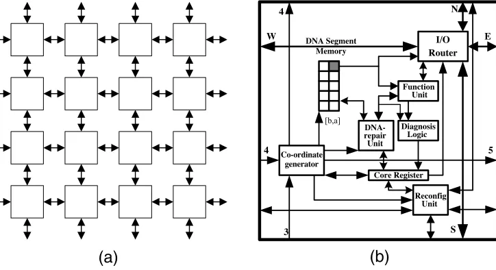
In a generic embryonic model, nature’s three-dimensional realizations of systems, because of current limitations of available technolog y, have to be ‘‘flattened’’ to systems built from two-dimensional homogeneous arrays of identical cells, which are interconnected so as to create the required functionality of the organism (Figure 3a). Perhaps if we succeeded in applying some fundamental biological processes of nature to the world of electronics, namely multicellular organization, cellular division, and cellular differentiation [21], then we could build nature-like systems that could grow, develop, evolve, and learn.
In embryonics, as in nature, the basic building block of any system is a cell. It is clear that the design of an embryonic cell architecture and associated system requires rigorous examination of the constraints imposed by environmental differences (e.g., the three-dimensional human body versus the two-dimensional silicon) and by process differences (e.g., protein synthesis versus gate synthesis), under which a biological cell and its proposed electronic counterpart has to function. Quite clearly the creation of an embryonic cell and system that is a pure generic equivalent of a biological cell and organism is not possible. However, a great deal can still be learned from nature, and from the way biological and physiological structures and processes have evolved. We may hope that by adapting this knowledge we can solve engineering problems that have hitherto frustrated us.
[image:4.504.103.405.438.639.2]Hugo de Garis in 1991 was the first scientist who defined and discussed embryonics [12]. He also implemented an artificial embryo [12, 11, 13] on a Darwin machine [10, 16]. Inspired by nature, this was the first ever attempt to ‘‘grow’’ an embryo on a two-dimensional cellular system using an artificial embryonic development mechanism to form some desired functionality. Later, he also demonstrated the feasibility of cellular differentiation [14] and self-reproduction in cellular automata [15, 18, 17]. In 1993 Mange and Stauffer [21] discussed the concept of embryonics, which they and others further developed [26] in greater detail. They identified the three funda-mental properties of living things that an electronic system, if inspired by nature, must also satisfy: multicellular organization, cellular differentiation, and cellular division. Using MUXTREE cells [24], they illustrated the mechanism of self-repair [27, 22, 25] and proposed four levels of
organization for an embryonic system [23]: the molecular level, cellular level, organism level, and population level. In 1998, based on the MUXTREE principle of hardware realization, Ortega and Tyrell recommended a different embryonic model [29] that only applied a two-level structure, with a cellular level and an organism level. Both approaches meet and fulfil all three fundamental properties of their biological counterparts.
In any living being each and every one of its cells carries the same DNA that describes the entire characteristic of the organism. Therefore the DNA of a generic hardware equivalent of a biological cell should also contain the entire behavior of the system. However, to meet this requirement in hardware is hugely impractical. It would simply mean that every single cell should contain the desired behavior — the genome — of the entire system. For example, let us consider a hypothetical implementation, requiring one million embryonic cells, where every cell’s gene is transcribed onto one byte of binary behavior (configuration data). Under these circumstances, each cell would also be expected to hold the one million bytes of DNA behavior of the complete system. In practice, however, a cell would never need to hold more information than the gene it synthesizes and genes of adjacent cells that it might be required to synthesize, in a system self-repair process, if an error in its functional operation was detected.
The limitations of this strateg y are obvious, and there are two clear alternatives to it. First, we could restrict the size of the system or subsystem, namely, the number of cells it uses. In fact, applications to date have only considered small systems that use a rather limited number of embryonic cells. For example, the BioWatch [34, 32] on the BioWall [33] has only eight cells (six system cells and two spare cells); the Khepera robot controller [6] is implemented with six cells (one system cell, one immune cell, and four spare cells). In all these cases, the number of genes that each cell can carry imposes a natural constraint on the size of the system. An alternative approach [42] is to restrict the information content held by each embryonic cell, so that it no longer exactly mimics the structure and behavior of the biological cell, but will still maintain most of its system-building characteristics. This is the approach proposed in this article and by the others [37 – 40, 42].
4 Embryonics
[image:5.504.73.435.58.255.2]4.1 The Embryonic Cell
Figure 3b illustrates the internal structure of one cell. The multicellular organization of cells when a system is being realized is shown in Figure 3a. Cell-to-cell communication and detailed
[image:5.504.67.252.58.252.2]system interconnection are discussed in [37]. Internally every cell contains eight functional modules: a DNA segment memory, a DNA-repair unit, a function unit, diagnostic logic, an I/O router, a coordinate generator, a reconfiguration unit, and a core register. The coordinate generator cal-culates both the DNA segment memory’s pointer address and the cell’s own address in the array. The latter is dependent on its relative position with respect to its neighboring cells. The memory pointer is used to select one set of configuration data (gene) from a segment of the system’s DNA. The I/O router forwards to the function unit three input signals from the four neigh-boring cells and will connect its output to one of those cells. The function unit contains a 2 : 1 multiplexer-based universal logic element and a D-type flip-flop. Any error in the function unit is detected by the diagnostic logic. The DNA-repair unit detects and repairs any transient error in the DNA segment memory. Finally, depending on the status of the core register, the recon-figuration unit may kill the cell and reconfigure the array so that the faulty cell is replaced by a fully functional one.
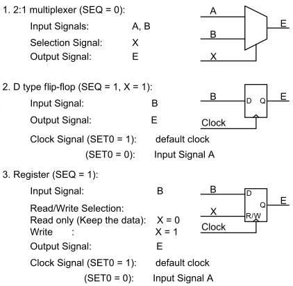
The task of the function unit is similar to the protein synthesis found in a biological cell. It will decode and transcribe the information of a segment of the DNA to an expected logic function. In a previous implementation [39, 38, 37] the function unit simply consisted of two 2 : 1 multiplexers and one D-type flip-flop. It was found, however, that cell functionality could be greatly improved if the number of multiplexers was increased to seven (Figure 4). Instead of the multiplexers an appropriate lookup table (LUT ) could also be employed. The core of the function unit (i.e., the 2 : 1 multiplexer for combinational logic and the D-type flip-flop for sequential function realisation [39]) will remain, but, with read/write control, the D type could also serve as a one-bit memory element. This change will not affect the size of the DNA and its genes, that is, the cell’s configuration data.
In addition to the A, B, X, Clock, and SEQ(the last is a bit in the gene that defines whether sequential functionality is required) inputs and a single outputE, there are three further inputs:N,
Pulse, andSET0. The signalNis an output from the function unit of a neighboring cell. Should the neighboring cell die, then this cell, during reconfiguration, will take over its functionality. ThePulse
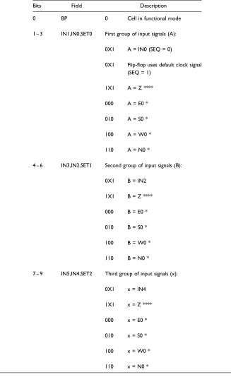
signal is equal to 1 for one clock cycle of the reconfiguration period, and 0 at all other times. If sequential mode of operation is required then, through the second bit of the gene, theSET0 sig-nal will instruct the function unit to operate either as a synchronous element (SET0 = 1, and the flip-flop is controlled by the systemClock) or as an asynchronous element (SET0=0, and flip-flop is controlled by signalA). The selection is controlled by multiplexerMUX_3in Figure 4. This means that, in order to meet both functional requirements of the cell, the gene definition will need to be slightly modified. The cell’s functionality is not affected, and it will continue to operate, as before, either in a functional mode or in a bypass mode. In the latter case, the function unit is inoperative and the cell only provides signal routing to and from other cells. The two modes of operation are illustrated in Tables 1 and 2 [39].
4.2 Cellular Division and Cellular Differentiation
Cell division is the initial step of populating an embryonic array with functionally configured cells. A mother cell, or zygote, will download the genome and distribute it to its adjacent cells, which, in turn, will pass this information to their neighboring cells. The process will continue until the whole array is populated. In the natural world, a biological cell needs time to gather enough nutrition to breed daughter cells. In the meantime, the hereditary material (i.e., the genome in the mother cell) will pass, during cell division, to the daughters. In the electronic world of embryonic arrays the mother cell will not breed new cells; these cells are fabricated during silicon processing. However, as in the natural world, the mother cell will still pass the genetic information on to its daughter cells. This procedure is called cellular division.
multiplexers or LUTs are used for data transmission, they behave as combinational logic elements. The consequence of this is that as soon as the mother cell receives a gene, it will immediately broadcast it to all its daughter cells. These will, in turn, pass on the genetic information to all their associated cells, and the process continues until the entire array is populated.
The time taken for this is the sum of all propagation delays in the longest chain of combinational elements. This must, in the worst case, be less than one clock cycle. In large and complex systems the time taken to populate the array may still become quite long. For such eventualities new population algorithms are currently under investigation.
[image:7.504.154.365.269.475.2]The process of cell division is shown in Figure 5. The DNA segment memory of each cell contains a counter. The cell’s own address and the position of the counter will determine which genes of the overall DNA structure each cell will hold in its segment memory. On completion of the
Table 1. Functional mode definition.
Bits Field Description
0 BP 0 Cell in functional mode
1 – 3 IN1,IN0,SET0 First group of input signals (A):
0X1 A = IN0 (SEQ = 0)
0X1 Flip-flop uses default clock signal (SEQ = 1)
1X1 A = Z ****
000 A = E0 *
010 A = S0 *
100 A = W0 *
110 A = N0 *
4 – 6 IN3,IN2,SET1 Second group of input signals (B):
0X1 B = IN2
1X1 B = Z ****
000 B = E0 *
010 B = S0 *
100 B = W0 *
110 B = N0 *
7 – 9 IN5,IN4,SET2 Third group of input signals (x):
0X1 x = IN4
1X1 x = Z ****
000 x = E0 *
010 x = S0 *
100 x = W0 *
cellular division process, a default memory pointer address will be computed by the coordinate generator. The gene that is currently executed by each cell will be selected as the right uppermost entry in DNA-segment memory, as shown in Figure 7 discussed within Section 4.3.2).
4.3 Cell Repair Strategies
There are two different types of repair mechanisms dealing with damaged cells in a biological system (Figure 2): DNA repair, which is internal to a cell, and repair via complete cell replacement. These mechanisms are the result of changed internal or external environmental conditions that adversely affect either the DNA information or the protein synthesis of the cell. Embryonics applies both of these processes in systems that it implements, when erroneous operation is detected.
4.3.1 DNA Repair
In living things many cells that possess a slow rate of reproduction, or for which cell division is not possible (postmitotic cells), will have to use their DNA information for weeks, months, or perhaps years (e.g., liver and brain cells). However, the DNA in living cells is subject to many alterations. Certain wavelengths of radiation, highly reactive oxygen radicals produced by the body, and chemicals in the environment are all agents that can damage the DNA. If the genetic information in the DNA is to remain uncorrupted, then such changes must be corrected. Uncorrected base changes in the DNA could result in the production of faulty proteins at an unacceptable rate (e.g., as in cancer). The evolutionary response to this problem has been the creation of a mechanism of the body that can repair the faulty DNA.
DNA-repair mechanisms [34] have been studied most extensively inE. coli(a bacterium) using a combination of genetic and biochemical approaches. Repair mechanisms can be divided into two broad categories: direct-repair and excision-repair. In the first category, the body’s enzymes directly repair the damaged DNA. In the second category, the damaged region is excised (removed) by specialized nuclease systems and then the gap is filled by DNA synthesis.
There is one major area where the DNA-repair mechanism of a hardware implemented cel-lular system must differ from its biological counterpart. Our bodies, for example, are made up of approximately 61013(sixty trillion) cells. Each cell stores the entire DNA that characterizes a human being. In the case of an electronic system, however, composed perhaps of millions of embry-onic cells, it would not only be impractical, but highly inefficient, for each cell to contain the entire genetic behavior ( DNA) of the organism. Each cell only acts upon and executes one, or at most a few,
Table 1. (continued)
Bits Field Description
10 – 11 OUT1,OUT0 Output signal group (E):
00 E1 = E **
01 S1 = E **
10 W1 = E **
11 N1 = E **
12 SEQ Flip-flop control bit:
0 Flip-flop is not used
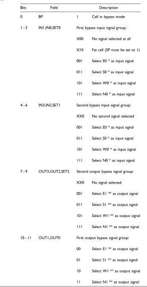
Table 2. Bypass mode definition.
Bits Field Description
0 BP 1 Cell in bypass mode
1 – 3 IN1,IN0,SET0 First bypass input signal group:
X00 No signal selected at all
X10 Fat cell (SP must be set to 1)
001 Select E0 * as input signal
011 Select S0 * as input signal
101 Select W0 * as input signal
111 Select N0 * as input signal
4 – 6 IN3,IN2,SET1 Second bypass input signal group:
XX0 No second signal selected
001 Select E0 * as input signal
011 Select S0 * as input signal
101 Select W0 * as input signal
111 Select N0 * as input signal
7 – 9 OUT3,OUT2,SET2 Second output bypass signal group:
XX0 No signal selected
001 Select E1 ** as output signal
011 Select S1 ** as output signal
101 Select W1 ** as output signal
111 Select N1 ** as output signal
10 – 11 OUT1,OUT0 First output bypass signal group:
00 Select E1 ** as output signal
01 Select S1 ** as output signal
10 Select W1 ** as output signal
genes of the genome that are associated with it as a result of system self-repair. Consequently, the cell does not need to detect errors in other parts of the genome and only needs to recognize them in the genes it may have to execute. This will reduce the complexity of the DNA-repair unit.
The direct DNA repair that living things are capable of cannot be easily implemented by electronic hardware. Excision repair, however, offers us an alternative way both to detect and to repair DNA errors in hardware-implemented embryonic cells [40]. This is also the first time that such DNA repair in an embryonic cell has been implemented. The process steps involved are similar to those found in biological systems:
First a DNA double helix is created (the cell’s gene is copied into the DNA-repair unit ).
The error in the gene used by the cell is detected, and the entire mutated gene is cleaved.
The DNA-repair unit removes the gene from the cell’s DNA memory.
Finally, the memory content is replaced by an undamaged copy of the strand, and the gene
is recovered.
The functional behavior of the unit is shown in Figure 6.
[image:11.504.131.371.73.153.2]The DNA-repair unit can repair any type of transient error in the gene that was to be executed by the embryonic cell. If the error it finds is a result of memory gene mutation, then a backup gene is used for the repair. Of course, no permanent faults found in the hardware could ever be repaired by this mechanism, and the unit is not capable of distinguishing between different types of transient and
Figure 5. Process of cellular division. Table 2. (continued)
Bits Field Description
7 – 9 OUT3,OUT2,SET2 10 Select W1 ** as output signal
12 SP Spare cell flag
0 Normal cell
[image:11.504.159.338.438.638.2]permanent faults. Therefore, in order to avoid the attempted repair of a permanent fault that will create an endless loop in the DNA-repair process, only a fixed number of DNA-repair iterations will be allowed to take place. Any further repair attempts are likely to be caused by faults that are permanent and therefore unrepairable. If the number of repairs exceeds a preset value, then an error flag and a cell ‘‘kill’’ signal will be set in the cell. Control of the cell, in this case, is handed over to the reconfiguration unit, which, via cell elimination [37], will restore the fault-free functionality of the embryonic array.
4.3.2 Cell Replacement Repair
When either the diagnostic logic above, or the DNA-repair logic, detects a fatal fault in any one of the cells, a reconfiguration mechanism is triggered. The integrity of the system, however, is not affected, so it can carry on functioning correctly while the error is corrected. This is because for error detection and repair, run-time algorithms are employed that use only combinational-elements and require less than a clock cycle. To achieve this, various cell replacement repair methodologies have been studied and implemented. Currently three types of cell replacement methods are employed: row elimination, row and column elimination, and cell elimination.
Row elimination:In a two-dimensional array of logic elements, the failure of one cell provokes the elimination of the corresponding row, which is replaced by the row to the north (above). Cells are then logically shifted upward until a spare row is reached and a new functional array is configured. Column elimination and row elimination in a 2D array are equivalent strategies.
Row-and-column elimination:First row elimination (or column elimination) will be triggered by the failure of a cell. If the cell does not configure correctly, then the column (or row) containing this cell will also be eliminated and it becomes transparent.
[image:12.504.137.367.56.270.2]Cell elimination:In the first instance spare cells on the right side of the array will replace faulty cells in the same row. Then, when the number of faulty cells in a row exceeds the number of spare cells assigned to that row, the whole row is eliminated.
Currently implemented systems employ all of the above cell replacement repair strategies. Cell elimination for molecular repair of a cell was first proposed by Mange et al. [25, 31]. In their system molecules represented the bottom-level ‘‘primitives’’ from which cells were built. When the numbers of spare molecules were exhausted and no more faulty molecules could be replaced, the whole cell was eliminated. On the higher, cellular level only one of the cell-elimination steps is used [22, 31]. Row elimination was first proposed by Ortega and Tyrell [29, 30]. Finally, row-and-column elimination is used by Canham and Tyrell [6, 5]. On comparing the three elimination mechanisms, cell elimination appears to be the most efficient. It is for this reason that the authors of this article propose the use of cell elimination during cell replacement repair [37].
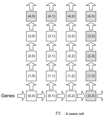
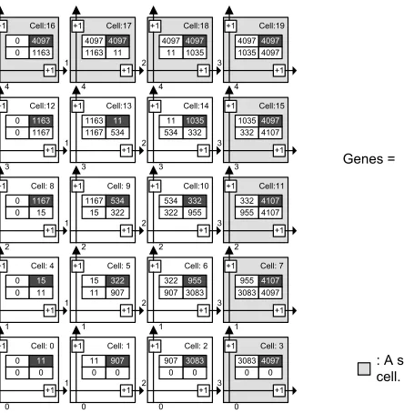
Once the type of cell repair strateg y to be used has been decided, the required size of a cell’s DNA-segment memory can be determined. Figure 7 shows a 54 embryonic array. The expected system functionality of the organism as configuration data is described by itsGenesmatrix (Figure 7). During cell division, the mother cell (0, 0) will transmit the genetic data to its daughter cells (Figure 5). Cell differentiation is achieved by each cell executing the right uppermost configuration data (gene) in its memory bank. Its address location is calculated and is pointed to by the cell’s coordinate generator. Currently executed genes of the cells (Figures 7 and 8) are shown in the top right hand corner of the cell. Spare cells are located on the right hand side and on the top of the array, forming one spare column and one spare row of cells.
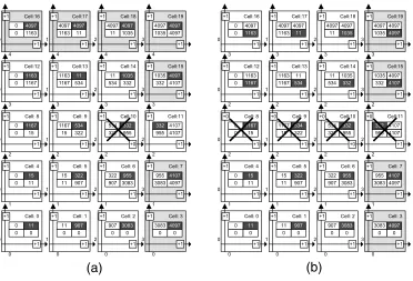
Let us consider the case of a fatal fault in cell 10 of Figure 7, the address of which is (2, 2). Cell elimination is undertaken in two steps (Figure 8a and b). First, it will be replaced by cell 11. Its address, which was previously (2, 3), will now change to (2, 2). The address pointer of cell 11 will also be modified so that it will now select the genetic code segment 332, which was previously executed by cell 10. With this final step, cell replacement is complete, the array is repaired, and normal system functionality continues uninterrupted.
[image:13.504.102.324.415.642.2]In Figure 8b it is assumed that a further fatal error develops, for example, in cell 9 of row 3. Clearly this cell will also need to be killed now. As a consequence, the second step of cell elimination is triggered, and the entire row of the faulty cell is deleted. When a cell or an entire row is eliminated, it becomes ‘‘transparent.’’ The cells in question will no longer provide any further functionality to the system, and they will merely be used for signal routing purposes by maintaining inter-cell
communication [37]. In the unlikely event that a fault in the cell’s I/O router module develops and thus it cannot even support inter-cell communication, then signals will be rerouted through the cell’s supervisory innate-immune system [41].
The above example also indicates that there is a direct relationship between the size of the memory each cell requires and the cell-elimination strateg y employed, namely, the numbers of spare rows and spare columns of the array. For example, besides its own genetic information, cell 14 will also need to store the genes of cells 9, 10, and 13. In case of an error, cell 14 will never be required to replace the functionality of any other cells apart from these, and therefore no other gene and configuration data needs to be stored in its memory. From this observation, if the number of spare columns iscand that of spare rows isd, the required size of memory that each cell should have can easily be calculated [42]:
m¼ ðcþ1Þðdþ1Þ ð1Þ
A fault-tolerant cellular organism can be built if both cell repair mechanisms — DNA repair and cell replacement — are present in the system. Figure 9 summarizes these mechanisms and shows the general relationship between cellular division, cellular differentiation, and cell repair.
5 Example: A 32-bit Static RAM
SRAM (static RAM) is read-write random access memory (RAM) that retains data bits in its mem-ory for as long as power is supplied. Unlike a DRAM (dynamic RAM), which stores bits in cells consisting of a capacitor(s) and a transistor(s), SRAM does not have to be periodically refreshed. SRAM provides faster access to data, but it can be more expensive than DRAM.
Figure 10 [35] shows a one-bit memory cell. It has three inputs (IN, SEL_L, andWR_L) and one output (OUT). When the memory cell is selected (SEL_L = 0) and a write command is
[image:14.504.69.441.55.308.2]issued (WR_L = 0), any data present on the line (signalIN) will be stored in memory. If a read command is issued (WR_L= 1) and the memory cell is selected, the memory will output the value it has stored on outputOUT. The output of each memory, to access a data bus, needs to be tri-state. Figure 11 shows a 32-bit SRAM module organized as a 4-byte system. It includes a 2-to-4 decoder, the inputs of which are connected to an address bus (A1 and A0). The decoder calculates the required addresses and issues a selection signal to the required byte. The system is enabled by aCS_Lchip select signal. When the memory module is selected (CS_L is 0) and a write command is received, data present on DIN7 to DIN0 will be stored in the memory under an address location specified by A1 and A0. When the output is enabled (OE_L is 0) and a read command is received, the content of the memory, as specified by A1 and A0, will be placed on the data bus DOUT7 to DOUT0.
A 32-bit memory system organized as 4 bytes was implemented using 1536 embryonic cells. The system occupies an array that consists of 64 rows and 24 columns. It also includes 2 spare rows placed on the top and 1 spare column placed on the right hand side of the array (Figure 13). The size of the DNA-segment memory is given by Eq. (1) as 6 (23). It is important to note that the size is independent of the number of cells (1536) in the array. As a consequence, the DNA-segment implemented system achieves a 99.61% and a 93.75% saving in required memory resources with respect to the Mange and Ortega systems, respectively. There is no limitation of or practical con-straint on the total number of cells that our proposed embryonic array could have.
[image:15.504.101.406.57.257.2]Simulation results of the memory module are shown in Figure 12. After cellular division and cellular differentiation the SRAM is loaded with a data stream F3, DE, 4B, and B5 for bytes 0, 1, 2, and 3 under corresponding address locations. At 3088 ns, a simulated error is injected into cell 258 located at row 10, column 18 (Figure 13). As the first step of cell elimination, cells are shifted right and the functionality of cell 258 will be taken over by cell 262. At 3092 ns, a second error is injected, but in this case into cell 253, located at row 10, column 13. Since there are no more spare cells in
[image:15.504.119.382.587.637.2]Figure 9. Cell repair strategies.
row 10, the row will be eliminated. The functionality of all rows from 10 to 61 will now shift upward by one row, and thus normal error-free operation of the array can continue unhindered.
6 Conclusions
[image:16.504.65.442.54.252.2]Embryonics is inspired by biological embryonic processes, during which a fertilized egg develops into an embryo, a multicellular organism. The birth of an artificial-life-based electronic system takes a similar route. The hardware platform is a ‘‘sea of cells’’ in a two-dimensional silicon array. Embry-onic processes of cellular division and differentiation will ultimately result in an organism — an electronic system — which behaves according to some specific requirement. The behavior of the system, similarly to nature, is defined by its DNA. The individual genes are downloaded and distributed over the array by a mother cell. Its daughter cells and their offspring will successively be assigned functional roles, via the encoded genes (Tables 1 and 2), and the collection of these roles
Figure 11. 4-byte static RAM system.
[image:16.504.63.445.464.640.2]will ultimately deliver the expected behavior of the organism. Should an error in the overall operation of the system be detected, then, according to the type of error, the faulty cells may first try to repair their DNA segments internally. If the cells are not repairable, then, through array reconfiguration, normal, error-free operation of the system continues.
Storing only a segment of the DNA in the memory of each cell overcomes complexity and information processing bottleneck problems that previously suggested embryonic systems possess. Furthermore, the size of the array and that of the system will no longer put an adverse constraint on the size of the memory, nor will the DNA memory limit the size of the system to be implemented. At the same time, sufficient information will be held by the DNA-segment memory at all times so that cell elimination can take place without the need of gene transmission between cells while the system is under repair. The overhead in terms of the support and repair logic required to undertake DNA repair and that required to supervise faultless cell operation is at present too high. Future research, using genetic computation, is aiming at reducing this complexity in order to arrive at economically more viable solutions.
The example of a SRAM, implemented by 1536 embryonic cells, illustrates the unique power of embryonics and a possible way forward in building larger and more complex self-repairing fault-tolerant systems based on an artificial life approach. Currently cell elimination can only be triggered in our proposed embryonic-cell-based system by errors detected either in the cell’s function unit or in its DNA-segment memory. Erroneous operation in any of the other modules of the embryonic cell cannot at present be reliably detected. To remedy this, work is currently being undertaken [41] by the authors using an enhanced immunoembryonic model.
References
1. Balinsky, B. I., & Fabian, B. C. (1981).An introduction to embryolog y, (5th ed.). New York: CBS College Publishing.
2. Benjamini, E., Coico, R., & Sunshine, G. (2000).Immunolog y: A short course, (4th ed.). New York: Wiley. 3. Bradfield, P., Dodds, J., Dodds, J., & Taylor, N. (2003).AS level biolog y. New York: Pearson
Education Limited.
4. Campisi, J., & Warner, H. R. (2001). Aging in mitotic & post-mitotic cells. In B. A. Gilchrest & V. A. Bohr ( Eds.),Advances in cell aging and gerontolog y, Vol. 4( pp. 1 – 16). Amsterdam: Elsevier Science. 5. Canham, R. O., & Tyrell, A. M. (2002). A multilayered immune system for hardware fault tolerance
within an embryonic array. In J. Timmis & P. J. Bentley ( Eds.),1st International Conference on Artificial Immune Systems, ICARIS2002( pp. 3 – 11). University of Kent at Canterbury Printing Unit.
6. Canham, R. O., & Tyrell, A. M. (2003). A hardware artificial immune system and embryonic array for fault tolerant systems.In Genetic Programming & Evolvable Machines,4(4), 359 – 382.
7. Carlson, B. M. (1981).Patten’s foundations of embryolog y, (4th ed.). New York: McGraw-Hill. 8. Curtis, H., & Barnes, N. S. (1989).Biolog y, (5th ed.). New York: Worth Publishers. 9. Darwin, C. (1998).The origin of species,edited with and introduction and notes by G. Beer.
Oxford, UK: Oxford University Press.
10. de Garis, H. (1990). Genetic programming: Modular evolution for Darwin machines. InProceedings of International Joint Conference on Neural Networks( pp. 194 – 197). Mahwah, NJ: Lawrence Erlbaum. 11. de Garis, H. (1991). Brain building: The genetic programming of artificial nervous systems and
artificial embryos. In O. M. Omidvar ( Ed.),Progress in Neural Networks, Vol. 4. Amsterdam: Ablex. 12. de Garis, H. (1991). Genetic programming: Artificial nervous systems, artificial embryos and
embryological electronics. In H. P. Schwefel & R. Ma¨nner ( Eds.),Parallel problem solving from nature. Berlin: Springer Verlag.
13. de Garis, H. (1992). Artificial embryolog y: The genetic programming of an artificial embryo. In B. Soucek ( Ed.),Dynamic, genetic, and chaotic programming (Chap. 14). New York: Wiley. 14. de Garis, H. (1992). Artificial embryolog y: The genetic programming of cellular differentiation.
15. de Garis, H., Iba, H., & Furuya, G. (1992). Differentiable chromosomes: The genetic programming of switchable shape-genes. In R. Ma¨nner & B. Manderick ( Eds.),Parallel Problem Solving from Nature ( pp. 489 – 498). Amsterdam: Elsevier Science.
16. de Garis, H. (1993). Evolvable hardware: The genetic programming of a Darwin machine. In
R. F. Albrecht, C. R. Reeves, & N. C. Steele ( Eds.),Artificial neural nets and genetic algorithms( pp. 441 – 449). Berlin: Springer-Verlag.
17. de Garis, H. (1993). Evolving a replicator: The genetic programming of self reproduction in cellular automata.ECAL-93: Self-organisation and life: From simple rules to global complexity( pp. 274 – 284). Universite´ Libre de Bruxelles.
18. de Garis, H. (1999). Aritificial embryolog y and cellular differentiation. In P. J. Bantley ( Ed.),Evolutionary design by computers( pp. 281 – 295). San Mateo, CA: Morgan Kaufman.
19. Kalthoff, K. (1996).Analysis of biological development. New York: McGraw-Hill.
20. Lodish, H., Baltimore, D., Berk, A., Zipursky, S. L., Matsudaira, P., & Darnell, J. (1998).Molecular cell biolog y, (3rd ed.). New York: W. H. Freeman.
21. Mange, D., & Stauffer, A. (1994). Introduction to embryonics: Towards new self-repairing and self-reproducing hardware based on biological-like properties. In N. Magnenat Thalmann & D. Thalmann ( Eds.),Artificial Life and Virtual Reality( pp. 61 – 72). Chichester, UK: Wiley. 22. Mange, D., Goeke, M., Madon, D., Stauffer, A., Tempesti, G., & Durand, S. (1996). Embryonics:
A new family of coarse-grained field-programmable gate arrays with self-repair and self-reproducing properties. In E. Sanchez & M. Tomassini ( Eds.),Towards evolvable hardware: The evolutionary engineering approach. Berlin: Springer-Verlag.
23. Mange, D., & Tomassini, M. (Eds.) (1998).Bio-inspired computing machines: Towards novel computational architectures. Lausanne, Switzerland: Presses Polytechniques et Universitaires Romandes.
24. Mange, D., Stauffer, A., & Tempesti, G. (1998). Embryonics: A microscopic view of the molecular architecture. In M. Sipper, D. Mange, & A. Pe´rez-Uribe ( Eds.),Evolvable systems: From biolog y to hardware( pp. 185 – 195). Berlin: Springer-Verlag.
25. Mange, D., Stauffer, A., & Tempesti, G. (1998). Embryonics: A macroscopic view of the cellular architecture. In M. Sipper, D. Mange, & A. Pe´rez-Uribe ( Eds.),Evolvable systems: From biolog y to hardware( pp. 174 – 184). Berlin: Springer-Verlag.
26. Mange, D., Sipper, M., Stauffer, A., & Tempesti, G. (2000). Towards robust integrated circuits: The embryonics approach.Proc. IEEE,88(4), 516 – 541.
27. Marchal, P., Nussbaum, P., Piguet, C., Durand, S., Mange, D., Sanchez, E., Stauffer, A., &
Tempesti, D. (1996). Embryonics: The birth of synthetic life. In E. Sanchez & M. Tomassini ( Eds.), Towards evolvable hardware: The evolutionary engineering approach. Berlin: Springer-Verlag.
28. McKenzie, J. (1976).An introduction to developmental biolog y. Boston: Blackwell Scientific.
29. Ortega-Sanchez, C., & Tyrell, A. (1998). MUXTREE revisited: Embryonics as a reconfiguration strateg y in fault-tolerant processor arrays. In M. Sipper, D. Mange, & A. Pe´rez-Uribe ( Eds.),Evolvable systems: From biolog y to hardware. Berlin: Springer-Verlag.
30. Ortega-Sanchez, C. A. (2000).Embryonics: A bio-inspired fault-tolerant multicellular system.Ph.D. thesis. University of York.
31. Prodan, L., Tempesti, G., Mange, D., & Stauffer, A. (2000). Biolog y meets electronics: The path to a bio-inspired FGPA. In J. Miller, A. Thompson, P. Thompson, & T. C. Fogarty ( Eds.),Evolvable systems: From biolog y to hardware( pp. 187 – 196). Berlin: Springer-Verlag.
32. Stauffer, A., Mange, D., Tempesti, G., & Teuscher, C. (2001). A self-repairing and self-healing electronic watch: The BioWatch. In Y. Liu et al. ( Eds.),Proceedings of the 4th International Conference on Evolvable System: From Biolog y to Hardware (ICES2001)( pp. 100 – 111). Berlin: Springer-Verlag.
33. Tempesti, G., Mange, D., Stauffer, A., & Teuscher, C. (2002). The BioWall: An electronic tissue for prototyping bio-inspired systems. In A. Stoica, J. Lohn, R. Katz, D. Keymeulen, & R. S. Zebulum ( Eds.),Proceedings of the 2002 NASA/DoD Conference on Evolvable Hardware (EH’2002)( pp. 221 – 230). Piscataway, NJ: IEEE Computer Society.
35. Wakerley, J. F. (2000). Digital design principles and practices, (3rd ed.), pp. 854 – 857. Upper Saddle River, NJ: Prentice Hall.
36. Wolpert, L., Beddington, R., Brockes, J., Jessell, T., Lawrence, P., & Meyerowitz, E. (1998).Principles of development. Oxford, UK: Oxford University Press.
37. Zhang, X., Dragffy, G., Pipe, A. G., Gunton, N., & Zhu, Q. M. (2003). A reconfigurable self-healing embryonic cell architecture. In T. P. Plaks ( Ed.),Proceedings of the 2003 International Conference on Engineering of Reconfigurable Systems and Algorithms (ERSA’03).
38. Zhang, X., Dragffy, G., & Pipe, A. G. (2003). Bio-inspired reconfigurable architecture for reliable systems. In H. R. Abnia & L. T. Yang ( Eds.),Proceedings of the 2003 International Conference on VLSI ( VLSI’03) ( pp. 28 – 33). Las Vegas, NV: CSREA Press.
39. Zhang, X., Dragffy, G., Pipe, A. G., & Zhu, Q. M. (2003). Ontogenetic cellular hardware for fault tolerant systems. In H. R. Arabnia & L. T. Yang ( Eds.),Proceedings of the International Conference on Embedded Systems and Applications, ESA’03( pp. 144 – 150). Las Vegas, NV: CSREA Press.
40. Zhang, X., Dragffy, G., & Pipe, A. G. (2004). Repair of the genetic material in biologically inspired embryonic-cell-based systems. In H. R. Arabnia, M. Guo, & L. T. Yang ( Eds.),Proceedings of the International Conference on VLSI, VLSI’04( pp. 316 – 324). Las Vegas, NV: CSREA Press.
41. Zhang, X., Dragffy, G., Pipe, A. G., & Zhu, Q. M. (2004). Artificial innate immune system: An instant defence layer of embryonics. In G. Nicosia et al. ( Eds.),Artificial Immune Systems, Third International Conference, ICARIS 2004( pp. 302 – 315). Berlin: Springer-Verlag.
![Figure 1. Component aging in higher eukaryotic organisms [4].](https://thumb-us.123doks.com/thumbv2/123dok_us/665401.568852/3.504.131.371.517.646/figure-component-aging-higher-eukaryotic-organisms.webp)
![Figure 2. Alternatives for dealing with damaged postmitotic cells [4].](https://thumb-us.123doks.com/thumbv2/123dok_us/665401.568852/4.504.103.405.438.639/figure-alternatives-dealing-damaged-postmitotic-cells.webp)