provisions. Therefore, you must treat this software
just like
Qbook,
with the following single exception. Borland International authorizes you to make archival copies of the software for the . sole purpose of backing-up our software and protecting your investment from loss.By saying. "just like a book." Borland means, for example, that this software may be used by any number of people and may be freely moved from on~ computer location to another, so long as there is no possibility of it being used at one location while it's being used at another. Just like a book that can't be read by two different people in two different places at the same time, neither can the software be used by two different people in two different places at the same time. (Unless. of course. Borland's copyright has been violated.)
Borland International grants you (the licensed owner of Turbo Graphix Toolbox) the right to incorporate Graphix Toolbox routines into your programs. You may distribute your programs that contain Graphix Toolbox routines in executable form without restriction or fee, but you may not give away or sell any part of the actual Graphix Toolbox source code. You are not, of course, restricted from distributing your own source code.
Sample programs included on the Turbo Graphix Toolbox disk demonstrate how to use the Graphix Toolbox. You may edit or modify them and incorporate them into programs that you write without restriction or fee. Use of sample programs is governed by the same conditions and restrictions as outlined in the first paragraph above.
WARRANTY
With respect to the physical diskette and physical documentation enclosed herein, Borland International. Inc. ("Borland") warrants the same to be free of defects in materials and workmanship for a period of 60 days from the date of purchase. In the event of notification within the warranty period of defects in material or workmanship, Borland will replace the defective diskette or documentation. If you need to return a product. call the Borland Customer Service Department to obtain a return authorization number. The remedy for breach of this warranty shall be limited to replacement and shall not encompass any other damages. including but not limited to loss of profit. and special. incidental, consequential. or other similar claims.
Borland International. Inc. specifically disclaims all other warranties, expressed or implied, including but not limited to implied warranties of merchantability and fitness for a particular purpose with respect to defects in the diskette and documentation, and the program license granted herein in particular, and without limiting operation of the program license with respect to any particular application. use. or purpose. In no event shall Borland be liable for any loss of profit or any other commercial damage. including but not limited to special, incidental, consequential or other damages.
GOVERNING LAW
This statement shall be construed. interpreted, and governed by the laws of the state of California.
Second Edition Printed in U.S.A
version
1
Owner's Handbook
INTRODUCTION ... ... ... .... ... ... 1
What Can You Do With the Graphix Toolbox? ... 1
Structure of This Manual ... ... 4
Typography ... 5
The Distribution Diskette ... ... 5
Acknowledgements ... 6
Chapter 1. A COMPUTER GRAPHICS PRIMER ... 7
Pixels ... 7
Screens ... 7
Characters and Fonts ... 8
Coordinate Systems ... 9
Absolute Screen Coordinate System ... 10
World Coordinate System ... 10
Windows ... 11
Clipping ... ... ... 12
How to Use the Turbo Graphix Toolbox With Your Hardware ... 13
The IBM PC and True Compatibles ... ... 14
IBM Color Graphics Card ... 15
Hercules Monochrome Graphics Card ... 15
IBM Enhanced Graphics Adapter . ... ... 15
Heath/Zenith Z-100 Computer ... ... 15
Chapter 2. GETTING STARTED .. ... ... 17
Including Turbo Graphix Routines in Your Program ... 17
Drawing Points ... ... 18
Drawing a Single Point ... 19
Drawing a Cluster of Points ... 20
Drawing Points Using a World Coordinate System ... 21
Erasing a Point ... 22
Summary of Point Routines ... 22
Drawing Lines ... 23
Drawing a Single Line ... 23
Drawing a "Walking Line" ... 24
Summary of Line-Drawing Routines ... 26
Drawing Squares ... 26
Summary of Square-Drawing Routines ... 27
Drawing Circles ... 27
Displaying 4x6-Pixel Text ... 32
Summary of Text-Drawing Routines ... 34
Windows ... 34
Defining a Window... 34
Displaying a Drawing in a Window... ... ... ... 37
Moving Windows ... 39
Another Use for Windows: the Flow Chart .... ... 43
Summary of Window Routines ... ... ... 47
Pie and Bar Charts ... ... ... ... ... ... ... 48
Pie Charts ... ... 49
Bar Charts ... ... 53
Summary of Pie and Bar Chart Routines ... ... ... 58
Plotting Curves ... 59
A Simple Example: Plotting a Sine Curve ... ... 59
The DrawAxis Procedure ... 62
Drawing a Sine Curve with Axes ... ... 64
Polygon Modification Routines ... ... 66
Finding a World to Fit a Polygon ... ... ... 69
Solving Curve-Fitting Problems ... 73
Fitting a Curve with the Spline Procedure ... ... 73
Modeling a Curve with the Bezier Procedure ... ... 76
Summary of Polygon/Curve Routines ... 80
Screens ... 80
Saving and Loading Screens ... ... 80
Printing Screens ... 85
Chapter 3. TECHNICAL REFERENCE ... ... 91
Turbo Graphix Files ... ... 91
Basic System Files ... 91
Supplemental System Files ... ... 92
High-Level Command Files ... ... 92
A Sample Turbo Graphix Toolbox Program ... 94
Constant and Type Definitions ... ... ... 94
AspectFactor ... 95
BackgroundArray ... ... 96
CharFile ... 96
ConOutPtr ... ... ... ... ... 96
HardwareGrafBase ... ... ... ... ... ... 96
HeaderSizeGlb ... ... 96
IVStepGlb ... ... ... ... ... ... 97
MaxBackground ... ... ... ... ... 97
MaxForeground ... ... ... ... ... ... 97
MaxWindowsGlb ... ... ... ... ... ... 98
MaxWorldsGlb ... ... ... ... ... ... ... 98
Min Background ... 99
MinForeground ... 99
PieArray ... 99
PlotArray ... 100
RamScreenGlb ... 100
ScreenSizeGlb ... 101
StringSizeGlb ... 101
WrkString ... ... ... ... ... 101
XMaxGlb ... ... ... ... .... 102
XScreenMaxGlb ... 102
YMaxGlb .... ... ... ... ... ... 102
Quick Reference Guide to Turbo Graphix Routines ... 103
Procedures and Functions ... ... ... 107
BaseAddress ... 108
Bezier ... 109
ClearScreen ... 112
ClearWindowStack ... 113
Clip ... 114
Clipping ... ... 115
CopyScreen ... 116
CopyWindow ... .... ... ... ... 117
DC ... 118
DefineHeader ... 119
DefineTextWindow ... 120
DefineWindow ... 122
DefineWorld ... 123
DisplayChar ... 124
DP ... 125
Draw Ascii ... 126
DrawAxis ... ... ... ... 127
DrawBorder ... : ... 129
DrawCartPie ... 130
DrawCircle ... ... ... 132
DrawCircleDirect ... 133
DrawCircleSegment ... 134
DrawCross ... 136
DrawCrossDiag ... 137
DrawDiamond ... 138
DrawHistogram ... 139
DrawPolarPie ... 144
DrawPolygon ... 146
DrawSquare ... 149
DrawSquareC ... 150
DrawStar ... 151
DrawStraight ... 152
DrawText ... 153
DrawTextW ... 155
DrawWye ... ... ... ... ... ... .... 156
EnterGraphic ... ... 157
Error ... 158
FindWorld ... 159
GetAspect ... 160
GetColor ... 161
GetErrorCode ... 162
GetLineStyle ... 163
GetScreen ... 164
GetScreenAspect ... 165
GetVStep ... 166
GetWindow ... ... ... .... ... 167
GotoXY ... 168
GotoXYTurbo ... 169
HardCopy ... 170
HardwarePresent ... 171
Hatch ... 172
InitGraphic ... 173
InvertScreen ... 175
InvertWindow ... 176
LeaveGraphic ... 177
LoadScreen ... 178
LoadWindow .... ... ... ... ... ... ... .... ... ... ... 179
LoadWindowStack ... ... 180
MoveHor .. .... .... ... ... ... ... ... ... ... ... 181
MoveVer . ... ... ... ... ... ... ... .... ... ... 182
PD ... 183
PointDrawn ... 184
RedefineWindow ... 185
RemoveHeader ... 186
ResetWindowStack ... 187
ResetWindows ... 188
ResetWorlds ... 189
RestoreWindow ... 190
RotatePolygon ... ... 191
SaveWindow ... ... ... .... ... .... ... ... .... ... 194
SaveWindowStack ... 195
Scale Polygon ... 196
SelectScreen ... 197
SelectWindow ... 198
SelectWorld ... 199
SetAspect ... 200
SetBackground ... 201
SetBackground8 ... 202
SetBackgroundColor ... 203
SetBreakOff ... 204
SetBreakOn ... 205
SetClippingOff ... 206
SetClippingOn ... 207
SetColorBlack ... 208
SetColorWhite ... 209
SetForegroundColor ... 210
SetHeaderOff ... 211
SetHeaderOn .... ... ... ... ... ... ... ... ... ... ... 212
SetHeaderToBottom ... 213
SetHeaderToTop ... 214
SetLineStyle .... ... ... .... ... ... ... .... ... ... ... ... 215
SetMessageOff ... ... ... ... ... 216
SetMessageOn ... 217
SetScreenAspect ... .... ... ... ... ... ... ... ... 218
SetVStep .. ... ... ... ... ... ... 219
SetWindowModeOff ... 220
SetWindowModeOn ... ... ... ... ... ... 221
Spline ... 222
StoreWindow ... 224
SwapScreen ... 226
TextDown ... 227
TextLeft ... 228
TextRight ... 229
TextUp ... 230
TranslatePolygon ... 231
WindowMode ... .... .... ... ... .... ... ... ... ... 232
WindowSize . ... ... ... ... ... ... ... ... 233
WindowX ... ... ... ... ... ... ... ... ... 234
The IBM Color Graphics Card ... ... .... ... ... .... ... ... 237
Color ... 238
Text ... 239
The Hercules Monochrome Graphics Card ... 239
Color ... 240
Text ... 240
Special Notes... 240
The Zenith Color Graphics Card ... 241
Color ... 242
Text ... 242
Compatibility Issues ... 242
Screen Size ... 243
Text Placement ... 243
Color ... 246
Speed ... 246
Premature Termination ... 247
Appendix B. GLOSSARy... ... ... ... .... ... ... ... ... 249
INDEX ... 253
LIST OF FIGURES
0-1 A Sampler of Drawings Done with the Graphix Toolbox ... 20-2 Stacked Windows ... 3
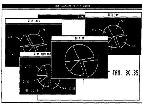
0-3 Variations on a Pie Chart ... 3
0-4 Two Curves Displayed with Coordinate Axes ... 4
1-1 The Clipping Option Used To "Zoom In" on a Drawing ... 13
2-1 A Single Point (DRWPNT.PAS Example) ... 19
2-2 A Cluster of Points (DRWPNTS.PAS Example) ... 20
2-3 Previous (DRWPNTS.PAS) Example on Hercules Screen ... 21
2-4 A Line (DRWLlN.PAS Example) ... 24
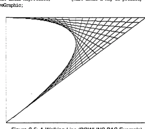
2-5 A Walking Line (DRWLlNS.PAS Example) ... 25
2-6 Squares (DRWSQ.PAS Example) ... 27
2-7 Circles (DRWCIR.PAS Example) ... 29
2-8 Machine-Dependent Text (DRWSTXT.PAS Example) ... 31
2-9 4x6-Pixel Text (DRWATXT.PAS Example) ... 33
2-10 A Window (SIMPWIND.PAS Example) ... 36
2-11 Three Windows (MULTWIND.PAS Example) ... 39
2-12 Moving a Window (MOVEWIND.PAS Example) ... 42
2-15 A Bar Chart (ONEHIST.PAS Example) ... 55 2-16 Pie and Bar Chart Displaying Same Data
(PIEHISTO.PAS Example) ... 58 2-17 Plotting a Smooth Curve (ONEPOLY.PAS Example) ... 61 2-18 Labeled Axes (ONEAXIS.PAS Example) ... 63 2-19 A Smooth Curve and Coordinate Axes
(POL YAXIS.PAS Example ... 65 2-20 Finding a World for a Polygon (FINDWRLD.PAS Example)... 72 2-21 Finding a Smooth Curve with Cubic Splines
(INTERP.PAS Example) ... 76 2-22 Finding Points to Fit a Smooth Curve of
Welcome to the Turbo Graphix Toolbox. The procedures and functions that make up this software package will expand your repertoire of Turbo Pascal programming tools. With the aid of the Graphix Toolbox, you can develop high-resolution monochrome graphics for IBM PC and PC-compatible computers (using either an IBM or Hercules graphics card), and the Zenith Z-100 computer.
This manual makes extensive use of Turbo Pascal programming exam-ples; a good working knowledge of Turbo Pascal is assumed. If you need to brush up on your Pascal knowledge, refer to the Turbo Pascal
manual, and/or the Turbo Tutor.
What Can You Do With the Graphix Toolbox?
The Turbo Graphix Toolbox is a versatile package, designed for both simple and complicated graphics applications. Simple procedures allow you to draw
• Points
• Lines
• Rectangles with optional shading
• Ellipses
• Circles
2
• Labeled pie charts
• Bar charts with programmable shading
• A variety of curves, using different linestyles and with optional smoothing
• Curve fitting
• Line and solid modeling
• Labeled coordinate axes
• Polygons of any shape, with optional rotation or translation
All your drawings can be displayed either on the full screen, or in win-dows that you define. You can also draw on a RAM (virtual) screen in memory, without display, and move the resulting images to the displayed screen when desired.
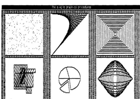
Here are some examples of the kind of drawings you'll soon be able to generate with the Graphix Toolbox.
, ~': I", " •• • •
. ,' ... :, .
':.'
.',":,.,:'". I':: '" ,.' . "
t ,I. , ,: " I ~ . . . ' : : . ' '" • : [image:14.404.98.345.307.482.2]•.• ',:,',':'.' :" I , , ' •• ' .... ,
Figure 0-1: A Sampler of Drawings Done with the Graphix Toolbox
Line 8 ColuM
L----I----I----I--'r==========:=!!!!:=!!!!:=!!!!=:=,11 This is
a
deMOnstMinda ... a1.;" n.. I
Mindo,;:=:==============;
All
r
Minda outsi
[image:15.402.84.320.82.257.2]the allo
Figure 0-2: Stacked Windows
JAM
I30
J5
[image:15.402.78.324.289.471.2]0.11 O.H 0.'1
o.n
O.H 0.71 O.SS 1.00
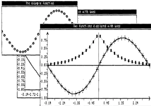
·3.1H.1H
1.00'0\--.,...,...-...-...--...---+-...,...-.---.---.--.--...--4
[image:16.403.96.340.75.247.2]·3.1' ·ZH ·US ·US i).I! US 2.H
Figure 0-4: Two Curves Displayed with Coordinate Axes
Structure of This Manual
4
This manual is divided into five parts:
• Chapter 1 provides an overview of the Turbo Graphix Toolbox. Basic graphics terms you need to know in order to use the toolbox are defined, and illustrations of some of the things you can draw are given. This chapter also talks about the different hardware configurations that can run the Turbo Graphix Toolbox.
• Chapter 2 gets you started on using the Turbo Graphix Toolbox. Tur-bo Pascal examples for the most commonly used procedures are given, along with the resulting drawings. You'll also see how to define and manipulate windows, and save and print the graphic images you create.
• Chapter 3 is the technical reference part of the manual. All the con-stants, types, procedures, and functions contained in the Turbo Gra-phix Toolbox are described, in alphabetical order, with parameters, function, restrictions, and examples.
• Appendix A explains how to use the Turbo Graphix Toolbox with different hardware configurations.
• Appendix B provides a glossary of terms used in the manual.
Typography
The body of this manual is printed in normal typeface. Special charac-ters are used for the following special purposes:
Alternate
Italics
Boldface
Al ternate characters are used in program examples
and procedure and function declarations.
Italics are used to emphasize certain concepts and termI-nOlogy, such as predefined standard identifiers, parame-ters, and other syntax elements.
Boldface type is used to mark reserved words, in the text as well as in program examples.
Refer to the Turbo Pascal Reference Manual for a complete description of the syntax, special characters, and overall appearance of the Turbo Pascal language.
The Distribution Diskette
The Turbo Graphix Toolbox distribution diskette contains the following:
• Installation and demonstration files
• Files containing all the procedures and functions
• All the commented program examples used in Chapter 2
Acknowledgments
6
In this manual, references are made to several products: • Flight Simulator is a registered trademark of Sublogic Inc. • Hercules is a registered trademark of Hercules Computer
Technology, Inc.
• IBM is a registered trademark of International Business Machines Inc. • MS-DOS is a registered trademark of Microsoft Inc.
• Turbo Pascal is a registered trademark of Borland International Inc. • Zenith Z-100 is a registered trademark of Heath Co.
A COMPUTER GRAPHICS PRIMER
Before you do any drawing with the Turbo Graphix Toolbox, you will need to understand the graphics and screen display terms used throughout this manual. Each of these concepts is described below, fol-lowed by a list of the Turbo Graphix procedures and functions that apply to each.
Pixels
The term pixel is an acronym for picture element. Pixels, in fact, are the basic elements that make up a video display image. The tiny dots that combine to make the text and graphic images you see on your comput-er monitor are pixels.
The Turbo Graphix Toolbox allows you to display pixels as black or white with monochrome cards, or in any color supported by a color card.
Screens
A screen is the configuration of pixels that make up displayed text or graphic images. Depending on the type of graphics card installed in your system, the screen display will be made up of the following horizontal-by-vertical pixel dimensions:
• IBM 640x200
• Hercules 720x350
Because the Hercules display is made up of a greater number of pixels, the graphic images created are finer in grain-that is, they are higher in resolution. Because of their higher resolution, they also take longer to draw. IBM and Zenith graphics images are coarser grained, and there-fore lower in resolution. The concept of resolution is easy to understand if you think of drawings made with pencils or pens; a drawing done with a fine-point drawing pen will be of a higher resolution, and will take longer to draw than one done with a blunt pencil.
For standard text display-that is, the text normally displayed by your system-a screen can also be thought of as a sequence of 80 vertical character columns that make up the width, and 25 lines of characters that make up the height.
There are two types of screens that you can use for creating images with the Toolbox: the screen displayed on your monitor, and a RAM (vir-tual) screen in memory. You can draw on either screen, but only the monitor screen is viewable; the RAM screen is invisible. The screen you are currently drawing on is called the active screen. RAM screens are useful for storing complicated images that are used often and are time consuming to redraw, or for animation, when it would be distracting to allow the computer to visibly redraw the screen.
The procedures and functions that are used to manipulate screens are:
ClearScreen CopyScreen GetScreen InvertScreen
LoadScreen SaveScreen SelectScreen SwapScreen
Characters and Fonts
8
A character is a letter, number, or symbol that is represented on your screen by a rectangular configuration of pixels. A sequence of charac-ters makes up a display of text.
There are two styles-or fonts-in which text can be displayed with the Turbo Graphix Toolbox:
• A simple, 4x6-pixel upper- and lower-case font that is used to display window headers, pie chart labels, or any text you wish to display in integer multiples of 4x6 pixels
• A larger, higher quality font (8x8 pixels with an IBM card, 9x14 pixels with the Hercules card, and 8x9 pixels with the Zenith card) that corresponds to the font normally used with the particular graphics card installed in your system
Exactly how the Turbo Graphix Toolbox utilizes these two fonts will be-come clear when you read the next section about coordinate systems.
The procedures and functions that affect text are:
DC
DefineHeader DefineTextWindow DisplayChar DrawAscii DrawText
Coordinate Systems
DrawTextW TextDown TextLeft TextRight TextUp
A coordinate system is a method used to identify a location according to its position relative to horizontal and vertical axes. In mathematics, usu-ally, and in Turbo Graphix Toolbox programming in particular, the hor-izontal axis is labeled X, and the vertical axis Y. The exact location of, for example, a point, is determined by the X and Y coordinates of that point-that is, its distance from the X and Y zero axes.
Absolute Screen Coordinate System
The absolute screen coordinate system refers to the entire monitor screen, and the actual character and pixel screen positions, for plotting text and graphics; coordinates [0,0] are in the upper left corner of the screen, with the X coordinates increasing to the right, and the Y coordi-nates increasing downward. As mentioned earlier, the screen can be re-garded either as a configuration of pixels or as a series of 25 lines by 80 columns.
Text is handled in two ways. The simple, 4x6-pixel font used for window headers and footers can be plotted anywhere on the screen, and can be scaled to be any size that is an integer multiple of 4x6 pixels (for exam-ple, 8x12). The higher quality font is plotted according to 80x25 text column and line coordinates.
World Coordinate System
For most graphics, the absolute screen coordinate system will not easily translate to the application's numeric values. A world coordinate system is an arbitrary coordinate system that you specify to accommodate your particular application. The numbers you use in your world coordinate system can be (and usually are) completely unrelated to pixel coordi-nates. In Turbo Graphix Toolbox language, this is called defining a world.
A world coordinate system can be used to scale images so that they fit correctly into the windows you have defined. After you define the world for a given window, any images you subsequently draw will be automati-cally, proportionately scaled to fit the window.
The procedures and functions that affect worlds are:
DefineWorld FindWorld
ResetWorlds SelectWorld
Windows
10
A window is any area of the screen that you define as the drawing area. Several windows, containing different drawings and text, can be defined and then displayed simultaneously on the screen. Each window can be moved independently of the other windows, placed on top of other win-dows, and stored to, recalled from, or erased from memory. Windows
can be stored and loaded individually or in groups to and from disk. Several windows can be stored in RAM, and quickly copied to and from the active screen. You can draw borders, incorporate high-quality text, and label your windows with headers or footers. The window you are currently drawing in is called the active window.
A window can be specified to be almost any size, from the whole screen to 1 vertical pixel by 8 horizontal pixels. You define a window area by specifying the X and Y coordinates of its upper left and lower right corners, with Y coordinates measured in 1-pixel units and X coordinates measured in 8-pixel units. These coordinates are called window definition coordinates. In window definition coordinates, the point [0,0] refers to the upper left corner of the screen.
Once you're working within a window, you can redefine its world coordi-nate system, thereby allowing multiple images to be displayed within one window, each with its own coordinate system. Coordinate axes, along with lettering, can be easily added to any drawing.
A special RAM memory area, the window stack, is set aside for tem-porary storage of windows. The stack comes in handy when you have several windows that you want to keep but don't want to display all at the same time. The stack is also used for storing windows that would otherwise be erased when another window is moved over them on the screen.
The procedures and functions that affect windows are:
Clipping
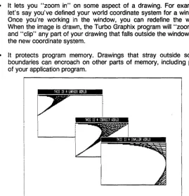
12
The Turbo Graphix Toolbox allows you to "clip" images at window boundaries if you wish. This feature accomplishes several purposes:
• It relieves you from having to be exact when you're drawing in a win-dow. The Toolbox does the nitty-gritty work of keeping your work within window boundaries.
• It lets you "zoom in" on some aspect of a drawing. For example, let's say you've defined your world coordinate system for a window. Once you're working in the window, you can redefine the world. When the image is drawn, the Turbo Graphix program will "zoom in" and "clip" any part of your drawing that falls outside the window with the new coordinate system.
• It protects program memory. Drawings that stray outside screen boundaries can encroach on other parts of memory, including parts of your application program.
THIS IS A lARm umo
[image:24.399.79.348.170.448.2]tHIS Ii A CORRECT UORLO
Figure 1-1: The Clipping Option Used To "Zoom In" on
a
DrawingThere are times when you'll choose not to clip drawings. For instance, you may develop a program using the clipping option, but once the pro-gram is debugged, and you know your drawings are within bounds, you can turn clipping off. This speeds up the drawing process considerably. Or, if you're working strictly with absolute coordinates, you don't need to worry about drawing outside screen boundaries.
How to Use the Turbo Graphix Toolbox With Your Hardware
There are a few differences between the computer systems and graph-ics cards that can run the Toolbox. In some cases, these differences re-quire your special consideration when creating Toolbox-based pro-grams.
There are two hardware considerations to take into account if you are using the IBM version of the the Turbo Graphix Toolbox: IBM compati-bility, and graphics cards. The information below will tell you briefly what you need to know about your particular system; more technical details about certain hardware configurations can be found in Appendix A.
The IBM PC and True Compatibles
The Turbo Graphix Toolbox runs on any IBM PC, PC Jr., and compati-ble computer. But what exactly is a true IBM-compatible computer? There are many computers on the market today that are billed as IBM-compatible, and to some extent they are. However, when considering whether a computer is IBM compatible, it is important to look at the specific application you are using the computer for. In the case of the Turbo Graphix Toolbox, you must consider whether the graphics displayed by your computer will be true to your program design.
A potential problem with some IBM compatibles is that their screen display is of a higher resolution than the IBM screen. The Corona PC is a good example. Although the Corona's higher resolution display can make for very high-quality text and graphics, graphic images created with the Turbo Graphix Toolbox will not display true-to-form on the Corona screen; because of the Corona's higher resolution, the drawing will appear to be compressed vertically.
A good test for whether your IBM-compatible computer will run the Toolbox is to test the Flight Simulator program (written for the IBM PC) on your system. If your computer can run Flight Simulator, it's a good bet it will also run the Toolbox without problems.
Below is a list of computers and graphics cards that are sure to run the Turbo Graphix Toolbox. Next to the name of the product, the Turbo Graphix Toolbox version that runs with that product is given in parentheses. If your computer or graphics card is not on this list, give a call to Borland's technical support staff; they'll be able to tell you wheth-er your computwheth-er will run the Graphix Toolbox.
AT&T PC 6300 (IBM) Columbia MBC, VP (IBM)
Compaq Portable and DeskPro (IBM) Comway Comgraphics card (Hercules) Comway Comtronics (IBM)
Comway Comcolor (IBM)
Heath/Zenith Z100 series (Zenith) Heath/Zenith Z150 series (IBM) Hercules color card (IBM)
Hercules monochrome card (Hercules) IBM Color/Graphics adapter (IBM) IBM Enhanced Graphics adapter (IBM) IBM PCjr (IBM)
Leading Edge PC (IBM) MA Systems PC Peacock (IBM) Panasonic SR Partner (IBM) Paradise/USI MultiDisplay (IBM) Paradise Modular Graphics Card (IBM) Profit Systems Multigraph (IBM) QuadRAM QuadColor I,ll (IBM) Seequa Chameleon line (IBM) STB Graphics Plus II (IBM) Tandy 1000 (IBM)
Tava (IBM)
Tecmar Graphics Master (IBM) TeleVideo PC (IBM)
Tseng Laboratories UltraPAK (Hercules) Vutek Color Plus (IBM)
IBM Color Graphics Card
14
If you have an IBM graphics card installed in your computer, your screen display is 640 pixels wide by 200 pixels tall. The SetBackground-Color and SetForegroundColor procedures are used to determine back-ground and display image colors. You can also use the SetColor-White and SetColorBlack procedures to reverse the background and foreground colors.
Hercules Monochrome Graphics Card
The Hercules graphics card produces a higher resolution display: 720 pixels wide by 350 pixels tall. The background of the display will be black, and the displayed images will be in the color produced by your monochrome monitor.
There are some important considerations to keep in mind when you de-cide to run your programs developed with a Hercules card on other sys-tems. These and other potential problems are discussed in Appendix A.
Heath/Zenith Z-100 Computer
GETTING STARTED
Ready to start drawing? This tutorial chapter takes you on a step-by-step tour of the Turbo Graphix Toolbox, using commented program ex-amples for both basic and sophisticated graphics routines. The exam-ples build on each other, so if you read the chapter through in order, by the end you should be ready to incorporate the Turbo Graphix routines you need into any graphics application program.
This chapter is designed as a basic tutorial. Technical details about the Turbo Graphix procedures used in this chapter can be found in Chapter 3. Basic graphics concepts and terminology used in this chapter are ex-plained in Chapter 1 and Appendix B.
Including Turbo Graphix Routines in Your Program
To use the Turbo Graphix Toolbox, you must first incorporate three basic system files in your program with the Turbo Pascal include direc-tive. The include directive is a comment that tells the compiler to read the program contained in the specified file. This directive starts with $1, followed by the file name and extension of the file to be included. To be understood by the Turbo Graphix Toolbox, the entire include directive must be enclosed within braces, i.e., ($I filename. ???). You must enter the include directive in the first column of your program text, before any code that utilizes the routines in the include file. Drive designations are also supported, and with Turbo 3.0, you can use full MS-DOS tree-structured directory path names.
Every Turbo Graphix program must include the following three system files, in the order given below.
{$I TYPEDEF.SYS} {$I GRAPHIX.SYS} {$I KERNEL.SYS}
You must copy the GRAPHIX file written for your hardware (supplied on the distribution disk) onto the GRAPHIX.SYS file. This is done by invok-ing the Turbo Graphix batch program, i.e., type tginst hgc or tginst ibm.
Next, before calling the Turbo Graphix routines you need for your particular application, you must initialize the graphics system by calling the InitGraphic procedure. At the end of your program, you must call
LeaveGraphic to return your system to text mode. See Chapter 3 for detailed information about these procedures.
All of the example programs in this chapter are included on the Turbo Graphix Toolbox distribution disk, so you can try out the examples and experiment with the calling parameters in the various procedures. Each example program is listed under a file name of the form FILENAME.PAS.
Every program example consists of five basic steps:
Include at least the three core Turbo Graphix files
Call InitGraphic to enter graphics mode
Call DrawBorder to draw a border around the drawing area (optional)
Draw your images or text
Include a wait loop so you can view the display (optional)
Call LeaveGraphic to return to text mode
Drawing Points
18
You can use the Turbo Graphix DrawPoint procedure to draw points us-ing either absolute screen or world coordinates. (See Chapter 1 for a definition of coordinate systems). The next two sections show you how to draw pOints using the screen coordinate system, while the section fol-lowing explains how points are drawn in world coordinates. You should read this section even if you aren't interested in drawing points, because the rest of the examples in this chapter utilize world coordinate systems; it is important that you understand the point-drawing examples in order to see the difference between screen and world coordinate systems.
Drawing
a Single Point
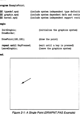
Writing a program that draws a single point is the simplest thing you can do with the Turbo Graphix Toolbox. Below is a Turbo Pascal program (DRWPNT.PAS on the distribution disk) that draws and displays a single pOint.
program EKamplePoint;
{$I typedef. sys} {$I graphix.sys} {$I kernel. sys}
begin
Ini tGraphic; Dra'llBorder;
DrawPoint ( 100, 1(0) ;
{include system independent type definitions} {include system dependent defs and routines} {include system independent support routines}
{initialize the graphics system}
{draw the point} rapeat until KeyPressed;
LeaveGraphic;
{wait until a key is pre~ {leave the graphics system}
[image:31.396.55.314.141.511.2]em.
Drawing
a
Cluster of Points
20
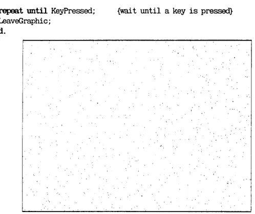
The following program (DRWPNTS.PAS on the distribution disk) draws 1000 points, displayed randomly on the screen. For this example, let's assume you have an IBM graphics card installed in your system.
p~ DrawPoints;
{$I typedef.sys} {$I graphix. sys} {$I kernel.sys}
var i: integer;
begin
Ini tGraphic; DrawBorder;
{include the graphics system code}
{ini t the system and screen}
for i : =1 to 1000 00 {draw 1000 random points on :I:J:N screen} DrawPoint(random(639),random(199));
repeat until KeyPressed; LeaveGraphic;
em.
[image:32.396.87.336.285.494.2]{wai t until a key is pressed}
Figure 2-2: A Cluster of Points (DRWPNTS.PAS Example)
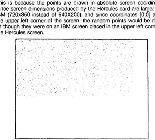
If you were to run this program on a system with a Hercules graphics card, the points would be drawn in the upper left corner of the screen. This is because the points are drawn in absolute screen coordinates. Since screen dimensions produced by the Hercules card are larger than IBM (720x350 instead of 640X200), and since coordinates [0,0] are in the upper left corner of the screen, the random points would be drawn as though they were on an IBM screen placed in the upper left corner of the Hercules screen.
, ' , , .... ' , ' r '," "::". ,';::'
"",:"
[image:33.398.59.321.102.338.2]I ' , '
Figure 2-3: Previous (DRWPNTS.PAS) Example on Hercules Screen
To avoid this skewed placement, and to allow you to run your program on systems with different graphics cards, you can write this program so that it uses a world coordinate system instead of the absolute screen coordinate system, as described next.
Drawing Points Using
a
World Coordinate System
A world coordinate system lets you define the addressing dimensions of your drawing area, independently of the screen type and size. Once you have defined your world, the Turbo Graphix program will scale the draw-ing to fit the screen or window you are usdraw-ing.
program WorldDr.awPoints;
{$I typedef. sys} {$I graphix. sys} {$I kernel.sys}
val' i:integer;
begin InitGraphic; Dr.awBorder;
DefineWorld(l,O, 1000, 1000,0); SelectWorld( 1) ;
SelectWindow( 1) ;
{include the gr.aphics system code}
{init the system and screen}
{define a world for dr.awing} {select it}
for i: =1 to 1000 00 {dr.aw 1000 r.and.om points on world} Dr.awPoint(r.andom(lOOO),r.andom(lOOO));
repeat until KeyPressed; LeaveGraphic;
em.
{wait until a key is pressed}
Erasing
a
Point
To erase a point, change the drawing color to black, and then draw the pOint, as follows:
SetCo1orBlack; Dr.awPoint(x,y) ;
Summary of Point Routines
22
DrawPoint draws a point in world or screen coordinates
DP draws a point in absolute screen coordinates only
PO returns TRUE if a point is drawn at specified screen coordinates
PointDrawn returns TRUE if a pOint is drawn at specified world coordinates
Drawing Lines
The DrawLine procedure allows you to draw and display lines in the current line style (selected by the SetLineStyle procedure). The coordi-nates for lines drawn in the following program examples are all calculat-ed using world coordinate systems.
Drawing
a
Single Line
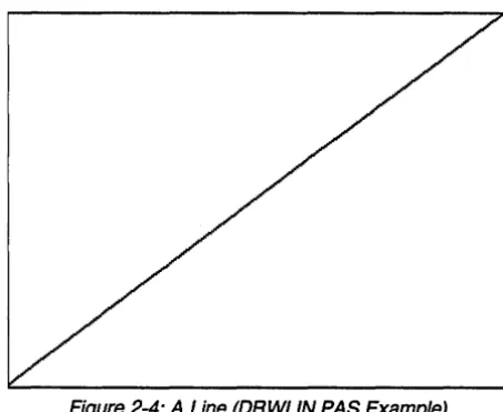
The following program (DRWLlN.PAS on the distribution disk) draws a line from the upper right to the lower left corner of the screen. Endpoint coordinates are passed to the procedure as the X and Y coordinates of the first endpoint, followed by the X and Y coordinates of the second endpoint.
program DrawLine;
{$I typedef. sys} {$I graphix.sys} {$I kernel. sys}
vat" i: integer;
begin Ini tGraphic; Drawf30rder;
{include graphics system}
{initialize the graphics system}
DefineWorld(l,O,lOOO, 1000,0); {define the world to draw in} SelectWor Id( 1) ;
SelectWindow( 1) ;
DrawLine(O,lOOO,lOOO,O);
repeat until KeyPressed; LeaveGraphic;
em.
{draw the line}
Figure 2-4: A Line (DRWLlN.PAS Example)
Drawing
a
"Walking Line"
24
An intriguing variation on the DrawLine procedure is the "walking line." A walking line program generates, by increments, a series of endpoint coordinates, thereby creating a "walking line." By changing the formula used to generate the endpoint coordinates, a variety of shapes can be drawn. In the example below (DRWLlNS.PAS on the distribution disk), the first endpoint moves uniformly across the top of the screen from left to right, while the other endpoint moves incrementally and diagonally from the upper right to the lower left corner of the screen.
program DrawLines;
{$I typedef.sys} {$I graphix.sys} {$I kernel.sys}
var i: integer;
begin
Ini tGraphic;
DefineWorld(l,O, 1000, 1000,0); SelectWorld( 1);
SelectWindow( 1) ;
SetBackground(O) ; DrawBorder;
{include the graphics system code}
{init the system and screen}
{define a world for drawing} {select it}
for i:=l to 20 00 DrawLine(i*50,O, lOOO-i*50,i*50);
repeat Wltil KeyPressed; LeaveGraphic;
em.
[image:37.397.77.309.289.495.2]{wai t until a key is pressed}
Summary
of
Line-Drawing Routines
Clip clips a line at active window boundaries
DrawLine draws a line using world or screen coordinates
DrawLineClipped clips a line at screen boundaries
DrawStraight draws a horizontal line
SetLinestyle selects one of five linestyles for drawing lines
GetLinestyle returns the current linestyle
Drawing Squares
26
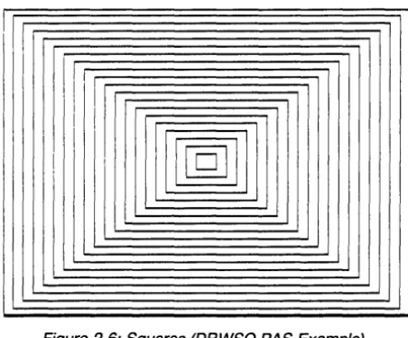
The DrawSquare procedure draws rectangles in the current line style (selected by the SetLineStyle procedure). A rectangle is defined by the coordinates of the points at its upper left and lower right corners. A boole-an value, Fill, allows you to fill the rectangle with the current drawing color (determined by the SetForegroundColor procedure). The following pro-gram (DRWSQ.PAS on the distribution disk) draws a series of consecu-tively larger squares around the center of the screen, with no fill. Another example program not illustrated here (DRWHCH.PAS on the distribution disk) draws hatched squares.
program DrawSquares;
{$1 typedef.sys} {$1 graphix.sys} {$1 kernel. sys}
val' i: integer;
begin
1ni tGraphic;
DefineWorld(1,0, 1000, 1000,0); SelectWorld( 1);
SelectWindow(l); DrawBorder;
{include the graphics system code}
{ini t the system and screen} {define a world for drawing} {select it}
for i: =1 to 20 do DrawSquare (500-i *25, 500-i *25, 500+i *25,500+ i *25, false) ; repeat until KeyPressed; {wai t until a key is pressed}
LBaveGraphic;
em.
II
II I
I[11]
[image:39.401.88.314.75.262.2]!
Figure 2-6: Squares (DRWSQ.PAS Example)
Summary
of
Square-Drawing Routines
DrawSquare draws a square using world coordinates
DrawSquareC draws a square using screen coordinates, but clipped at the boundaries of the active window
SetForegroundColor chooses the current drawing color
SetLinestyle chooses the line style
Drawing Circles
An aspect ratio is defined as the height-ta-width ratio of a circle or ellipse. Turbo Graphix circle routines allow you to vary the aspect ratio's vertical dimension by calling the SetAspect procedure. In addition, a global con-stant, AspectFactor, sets the system-dependent aspect ratio, so that an aspect ratio of 1.0 produces a true circle on a particular hard-ware screen.
The following program (DRWCIR.PAS on the distribution disk) draws a series of circles, and varies both their radii and aspect ratios. The parameters passed to the DrawCircle procedure specify the X and Y world coordinates of the center of the circle; the radius corresponds to the X (horizontal) dimension of the circle.
program DrawCirc;
{$I typedef. sys} {$I graphix.sys} {$I kernel. sys}
var i:integer; Aspectloo, rad: real.;
begin Ini tGraphic;
DefineWorld(l,O,lOOO,lOOO,O); SelectWorld( l) ;
SelectWindow( l) ; DrawBorder;
rad:=1.5;
Aspectloo: =GetAspect; SetAspect (0.2) ;
tor i:-l to 15 do begin
DrawCircle(500,500,rad); SetAspect(O.2+i/lO); rad: .. rad-O. 05;
em;
{include the graphics system code}
{ini t the system and screen} {define a world for drawing} {select it}
{set initial radius} {save default aspect ratio} {ini t i t for this routine}
{draw circles}
SetAspect (AspectI..oo) ; {restore previous aspect ratio}
repeat mtil KeyPressed; {wai t until a key is pressed} l..eaveGraphic;
em.
Figure 2-7: Circles (DRWCIR.PAS Example)
Summary of Related Routines
DrawCircle draws a circle or ellipse using world or screen coordinates
DrawCircleDirect draws a circle or ellipse using screen coordinates
DrawCircleSegment draws an arc of a circle
DrawPie draws a pie chart
GetAspect returns the current aspect ratio
SetAspect determines the aspect ratio for a circle
Text
Displaying Machine-Dependent Text
30
The text routines used by the Turbo Graphix Toolbox are very similar to those used by Turbo Pascal; the screen is defined as 25 lines by 80 columns (characters), and the Turbo Pascal procedures Go toXY, Write and WriteLN are supported by the Graphix Toolbox. However, there are· a few considerations specific to the Turbo Graphix text mode concern-ing the alignment of text with drawconcern-ings, and within windows. Since the size of the text font varies with the graphics card installed, some adjust-ments must be made when attempting to align text with drawings. In particular, Hercules text, which is defined on a 9-pixel horizontal boun-dary, must be adjusted for the 8-pixel window boundary. See Appendix A for technical information on text fitting.
The following program (DRWSTXT.PAS on the distribution disk) places the start of a text string at the center of the screen, demonstrates the automatic new-line performed by WriteLN, and places the text within a filled box whose dimensions are determined according to the world coor-dinate system. The coorcoor-dinates for the points at the corners of the box are computed from the character positions of the text.
program DrawSta.ndardI'ext;
{$I typedef.sys} {$I graphix.sys} {$I kernel. sys}
const MlxWorldX: real=lOOO.O; MlxWorldY: real=lOOO.O;
val' i:integer;
CharHeight,ChatWidth:real;
begin Ini tGraphic;
{include graphics system}
{initialize the graphics system}
DefineWorld(l,O,MlxWorldY,MaxWorldX,O); {define world to draw in} SelectWorld( 1);
SelectWindow(l); DrawBorder;
GotoXY(39,12); {goto the center of the text screen} writeln('* <- This should be at the center I); {do two lines of text} write('This should be on the next line');
ChafWidth:~orldX/80; CharHeignt:=MaxWorldY/25;
{compute a character's width} {compute a character's heignt}
DrawSquare(9*ChafWidth,7*CharHeignt, {draw box at text loc [la,S]} (22*ChafWidth ) +2, (S*CharHeignt ) +2, true) ;
GotoXY( la,S);
write( 'Text in a box' );
repeat until KeyPressed; I..eaveGraphic;
em.
rrext In a boxl
his should be on the next line
{wri te text in it}
{wait until a key is pre~ {leave the graphics system}
[image:43.404.73.327.131.432.2]* (-
This should be at the centerDisplaying 4x6-Pixel Text
32
The 4x6-pixel character set is used for window headers, and for applica-tions that require text that is smaller or larger than the machine-dependent text. Unlike the machine-machine-dependent text, the 4x6-pixel char-acters can be placed at any screen location. The Scale parameter passed to the DrawText procedure specifies the size of the characters (in integer multiples of 4x6 pixels); the larger the value of Scale, the larger the character.
Since a character in the 4x6-pixel font is made up of only a few pixels, this text is of a coarser quality than the machine-dependent text, even when they are scaled to the same size.
The following example (DRWATXT.PAS on the distribution disk) uses the DrawText procedure to display upper-case characters, in different positions and sizes, in the center of the screen. The complete character set is then displayed at the upper left corner of the screen, scaled to its smallest size.
program DrawAl ternateText;
{$I typedef. sys} {$I graphix.sys} {$I kernel. sys}
const MaxWorldX: real=lOOO.O; MaxWorldY: real=lOOO.O;
CharArrayl: array [0 .. 25] of char=
{include graphics system}
('A', 'B',
'e',
'D', 'E', 'F', 'G', 'H', 'I', 'J', 'K', 'L','M', 'N', '0', 'P', 'Q', 'R', 'S', 'T', 'U', 'V', 'W', 'X', 'Y', 'Z');
var i : integer;
CharHeight,ChatWidth:real;
begin
{define an array of characters}
Ini tGraphic; {ini tialize the graphics system}
DefineWorld(l,O,MaxWorldY,MaxWorldX,O); {define the world to draw in} SelectWorld( 1);
SelectWindow( 1) ; DrawBorder;
for i : .. 1 to 50 do {print random characters in center of screen} DrawrextW( random( 600 )+200, random ( 600 )+200,
random( 5) , CharArIa8l[ random ( 26) ] ) ;
DrawrextW(15,50,l, 'ABaEiGIIJKlMNO~'); {type chars in corner} DrawrextW(15, 100, 1, 'abodefghijklmnopqrstuvwxyz');
DrawrextW(15,l5O,1,' 1234567890-:0\1 I@#$%"&*( L+I'); DrawrextW(15,2OO,1, '[] 0:";, .o/?');
repeat mill KeyPressed; LeaveGraphic;
em.
!mEFGHIJKL~NCpmlUU~Hil
'~(Qelih i ,;k l~noPQrSluuwxy:
mmmo,:\"'el$;:,mi.'1 tlU :':, ,(}/~
[image:45.404.62.331.109.390.2]{wait until a key is pre~ {leave the graphics system}
Summary of Text-Drawing Routines
For machine-dependent text:
DC draws a character at the specified text coordinates
Define Text Window uses specified text coordinates to define a window
DisplayChar draws a character at the specified text coordinates
TextDown, TextLeft, TextRight, TextUp adjust space between window boundaries and text (text fitting)
For 4x6-pixel text:
DefineHeader defines a window header
DrawAscii draws a character at the specified screen coordinates
DrawText draws a character string at the specified screen coordinates
DrawTextW draws a character string at the specified world coordinates
Windows
This section tells you how to create and manipulate on-screen windows. The use of windows allows greater flexibility in graphics applications, since you can display several different drawings on the screen at once, using different world coordinate systems; and you are not limited to the pixel dimensions of the window.
Defining
a
Window
34
When the Turbo Graphix Toolbox is initialized with the InitGraphic pro-cedure, the entire screen is, in effect, defined as a window whose world coordinates correspond to the pixel dimensions of the screen. However, you can redefine any region of the screen as a window, from an 8x1-pixel (horizontal by vertical) box to the entire screen.
Once defined, a window acts more or less independently of other win-dows and even the screen. Winwin-dows can be small or large, moved around, drawn on with reference to their own coordinate systems and boundaries, and individually removed, stored, and retrieved.
Generally, you will want to define a new world coordinate system for every window you define; otherwise, any drawing you do in a window will take place as if the screen coordinate system were mapped to that window. All drawing routines-except routines internal to the graphics system, routines for machine-dependent text positioning such as Go toXY, and window positioning routines-can use world coordinate systems.
To associate a world with a window, you must always call SelectWorld before Select Windo w. If a new window is subsequently selected, the current world is retained. Thus, to draw alternately in two windows with different worlds, SelectWorld must be called before each SelectWindow:
repeat
SelectWorld( l); SelectWindow(l);
{ Insert code to draw something in window 1 USing world coordinate system 1 } SelectWorld(4) ;
SelectWindow(2) ;
{ Insert code to draw something in window 2 using world coordinate system 4 } mtil KeyPressed;
Besides Simply defining the dimensions of your window, you can label it with a header or footer, fill it in with a color or background pattern, or draw a border around it in any line style. When a new window is defined or an existing window is redefined, the header associated with that win-dow number is destroyed. This means that DefineWindow must be called before DefineHeader.
To change the dimensions of an existing window, without changing its header, use the RedefineWindow procedure.
36
program SimpleWindow;
{$I typedef. sys} {$I graphix. sys} {$I kernel. sys} {$I windows.sys}
Ini tGraphic; DraWBorder;
{these files must be}
{included and in this order}
{initialize the graphics system} {draw a border around the drawing} {area of the primary window}
DefineWindow( 1,10,20, XMaxGlb-lO, ~b-20); {define a window 80 pixels} {in from the left and right edges, and 2O} {from the top and bottom edges}
DefineHeader(l, ''!HIS IS AN EXAMFtE WINIXm'); {give it a header} SetlleaderOn;
SetBackground(85) ; SelectWindow(l) ; SelectWor Id( 1) ;
DefineWorld(l,O,lOOO,lOOO,O); Drav.i30rder;
repeat until KeyPressed; LeaveGraphic;
mxl.
{give i t a grey background} {select the window} {select the worl~
{give it a world coordinate system} {draw the border}
[image:48.407.79.352.106.505.2]{wait until a key is pre~ {leave the graphics system}
Figure 2-10: A Window (SIMPWIND.PAS Example)
Displaying
a Drawing in a Window
Suppose you want to display the "walking line" example in a window. You can display the example using a world coordinate system, and in any position on the screen by following these steps:
• Define the window
• Define the world coordinate system for the window
• Select the world coordinate system
• Select the window for drawing
• Draw a border (optional)
• Display the walking lines
The following example (MUL TWIND.PAS) displays the walking line ex-ample in three different windows, each with its own coordinate system, with the drawings clipped at window boundaries.
p~ MUltipleWindows;
{$I typedef. sys} {$I graphix. sys} {$I kernel. sys} {$I windows.sys}
var i: integer; procedure DrawLines;
var i: integer; begin
{these files must be}
{included and in this order}
38
begin
InitGraphic; Drav.Border;
{initialize the graphics system} {draw a border around the drawing} {area of the primary window}
{(the dimensions of the primary window} {defaul t to the screen dimensions)} DefineWindow(1,trunc(XMaxGlb/10),trunc(YMaxGlb/10),
trunc (XMaxGlb/2 ) , trunc (YMaxGlb/2) ) ;
{define a window one tenth of the way}
{in from the left and top edges, and half}
{way down from the right and bottom edges} DefineHeader(l, ''lliIS IS A I...AIGR WORID'); {give it a header}
DefineWorld( 1,0,2000,2000,0); {give it a larger world coord. system} DefineWindow(2,trunc(XMaxGlbl3),trunc(YMaxGlb/3),
trunc( (XMaxGlb*2)/3), trunc( (YMaxGlb*2)/3)); {define a window one third of the way}
{in from the left and top edges, and} {from the right and bottom edges}
DefineHeader(2, ''lliIS IS A CORRELT IDRLD'); {give i t a header} DefineWorld(2,0,lOOO,lOOO,0); {give it a correct world coord. system} DefineWindow(3,trunc(XMaxGlb/2),trunc(YMaxGlb/2),
trunc((XMaxGlb*9)/lO),trunc((YMaxGlb*9)/lO)); {define a window one half of the way}
{in from the left and top edges, and half}
{way down from the right and bot tom edges} DefineHeader(3, ''IHIS IS A SvWl..ER IDRLD'); {give i t a header}
DefineWorld(3,0,500,500,0); {give it a smaller world coordinate system}
for i:=l to 3 cb begin
SelectWorld( i) ; SelectWindow( i) ; SetHeaderOn; SetBackground(O) ; DrawBorder; DrawLines; em;
repeat until KeyPressed; LeaveGraphic;
em.
{select it} {select it}
{give i t a black background} {draw border}
{draw lines}
{wai t until a key is pressed} {leave the graphics system}
Figure 2-11: Three Windows (MUL TWIND.PAS Example)
Moving Windows
Once you've defined a window, you can move it to any position on the screen using the MoveVer and MoveHor procedures; windows are moved by increments (multiples of 8 horizontal pixels and multiples of 1 vertical pixel).
MoveHor and MoveVer work by automatically and continually refreshing the screen images over which the window is moved. They do this by storing the displayed screen image to the virtual screen.
40
For your windows to keep their integrity and to be moved independently, you must keep copies of all windows on the window stack, and store all screen images you want to keep on disk. For instance, if the screen contains two windows that you want to display independently-that is, you want to be able to move them around and place them on top of each other-you should do the following: using the SaveScreen pro-cedure, store the screen (without any windows) on disk, and store up-to-date copies of both windows on the window stack using the
StoreWindow procedure.
Every time you draw something in a window, or change what was previ-ously drawn, save a copy of the window on the window stack. When you want to move a window, save the presently displayed screen-without the window you plan to move-to the RAM virtual screen using the CopyScreen procedure, so the non-moving window is now also copied to the virtual screen. The virtual screen should now contain everything that was on the displayed screen, except the window you want to move. Now, draw the window you want to move on the screen, and use MoveHor and MoveVer to move the window around, without destroying the fixed images underneath.
The window stack is a RAM memory area where window images can be stored temporarily. You might want to use the stack when, for instance, you have defined and drawn in several windows but only want to display a few on the screen, or if one window is obstructing another and the ob-structed window needs to be displayed. Whole window stacks, as well as individual windows in the stack, can be stored to and recalled from disk using the Save Window and RestoreWindow procedures. Windows on the stack can be accessed in any order.
Windows can be restored from the stack to any location on the screen by specifying X and Yoffsets. To restore the window to its former posi-tion, use offsets of O.
If the window currently selected with the SelectWindow procedure is the same as the one being restored from the stack, the screen coordinates of the selected window will shift to match the offset of the restored win-dow. The selected window does not change when any other window is restored from the stack.
Stored windows and the RAM screen are dynamically allocated on the heap using the Turbo GetMem and FreeMem procedures. Therefore, the Mark/Release method of memory management should not be used in your programs.
The following program (MOVEWIND.PAS) shows how to move windows about on the screen; use the arrow keys to move the windows, and press the space bar to stop program execution.
program MJveWindows;
{$I typedef.sys} {$I graphix. sys} {$I kernel.sys} {$I windows. sys}
var i: integer;
Ch: char;
procedure DrawLines; var i: integer; begin
{these files must be}
{included and in this order}
for i:=l to 20 do DrawLine(i*50,O,lOOO-i*50,i*50);
em;
begin Ini tGraphic; DrawBorder;
{ini tialize the graphics system} {draw a border around the drawing} {area of the primary window}
{( the dimensions of the primary window} {defaul ts to the screen dimensions)} DefineWindow(l,trunc(XMaxGlb/lO),trunc(YMaxGlb/lO),
trunc(XMaxGlb/2),trunc(YMaxGlb/2));
{define a window one tenth of the way}
{in from left and top edges and half}
{way down from right and bottom edges} DefineHeader( 1, ''!HIS IS '!HE FIXED WINlX>W' ); {give it a header} DefineWorld( 1,0, 1000, 1000,0); {give i t a world coordinate system} DefineWindow(2,trunc(XMaxGlb/2),trunc(YMaxGlb/2),
trunc( (XMaxGlb*9)/lO), trunc( (YMaxGlb*9)/lO));
{define a window one half of the way}
{in from left and top edges, and half}
{way down from right and bottom edges} DefineHeader(2, ''!HIS IS '!HE MJVEAEl.E WINlX>W'); {give i t a header} DefineWorld(2,O,1000,1000,O); {give it a world coordinate system} SelectWorld(l); {select world}
SelectWindow(l); {select fixed window} SetHeaderOn;
42
DrawBorder; DrawLines; CopyScreen; SetBreakOff; SetMessageOff; SelectWorld(2) ; SelectWindow(2); SetHeaderOn; SetBackground( 0) ; DrawBorder; DrawLines;
repeat
read ( Kl:xi, Ch) ; case ord(Ch) of
em;
72 : MYveVer( -4, true) ;
75 ~veHor(-l, true);
71 ~veHor(l, true);
00 MYveVer(4, true);
until Ch=' ,.
LeaveGraphic;
em.
{draw the window} {draw lines in it}
{copy i t to the virtual screen} {don't error when edge hit}
{select world}
{select moveable window}
{give i t a black background} {draw the window}
{draw lines in it}
{read the keystroke}
{up arrow?} {left arrow?} {right arrow?} {down arrow?}
{space char exits program}
{leave the graphics system}
IHISI;IHEFImmoou
[image:54.399.75.333.62.522.2]IHI; E THE Momm U1NDDU
Figure 2-12: Moving
a
Window (MOVEWIND.PAS Example)Another Use for Windows: the Flow Chart
Anything that can be contained in a rectangle can be animated using windows. The following example (FLOWDEMO.PAS) animates a flow chart by using a moveable window. The drawing of the flow chart is the fixed screen image, while a window that contains the present state of the "machine" is moved along the flow chart drawing to show how the processor modifies variables when the program executes. The program increments a count and tests the result. If the count is not large enough, the program increments the count and tests again. When the count is high enough, the "program" is finished.
program Flo\\DelOO;
{$I typedef.sys} {$I graphix.sys} {$I kernel. sys}
{$I windows. sys}
procedure FlowChartDelOO;
var Xl, Yl, X2, Y2, i, Count: integer; Temp :wrkstring;
{these files must be}
{included and in this order}
procedure DrawArrowHor(Xl, Yl,X2,Y2:integer); {draw horizontal arrow} {with tip at point [X2,Y2]} begin
DrawLine(Xl, Yl,X2, Y2); if X2>Xl then
begin
DrawLine(X2-4, Y2-2,X2, Y2); DrawLine( X2-4, Y2+2, X2, Y2) ;
em
else begin
DrawLine(X2+5, Y2-2,X2, Y2); DrawLine(X2+5, Y2+2,X2, Y2);
em;
44
procedure DrawArrowVer(Xl, Yl,X2, Y2: integer); {draw vertical arrow}
begin
DrawLine (Xl, Yl, X2, Y2) ; if Y2>Yl then
begin
DrawLine (X2-2, Y2-3, X2, Y2) ; DrawLine (X2+2, Y2-3, X2, Y2) ; em
else begin
DrawLine (X2-2, Y2+3, X2, Y2) ; DrawLine(X2+2, Y2+3,X2, Y2); em;
em;
{with tip at point [X2, Y2]}
procedure Blink(Count, time: integer) ; {blink the current window} var i: integer;
begin for i: =1 to Count ck> begin
Delay ( time ) ; InvertWindow;
em;
em;
begin {FlowChartDemo} DefineWindow(l,O,O,79,185); DefineWindow(2,12,20,25,40); DefineWindow(3,15,55,22,75); DefineWindow(4, 11, 110,26, 130); DefineWindow(5,47,90,56,110);
ClearScreen; SetColorWhi te;
DefineHeader(l, 'A FLOW CHART'); SetHeaderOn; SelectWindow(l); DraM30rder; SetHeaderOff; SelectWindow(2) ; DraM30rder;
DrawText ( 125, Z7 ,2,
'srARl" ) ;
SetWindowModeOff;DrawArrowVer( 151,40,151,55) ;
SetWindowModeOn;
{define the 'F