Composing Multi-View Aspect Models
Olivier Barais IRISA University of Rennes 1,
Campus Beaulieu, Rennes, France [email protected]
Jacques Klein University of Luxembourg,
Campus Kirchberg, L-1359 Luxembourg [email protected]
Benoit Baudry IRISA / INRIA, Campus Beaulieu,
Rennes, France [email protected]
Andrew Jackson, Siobhan Clarke Computer Science Dpt, Trinity College Dublin 2, Ireland
[email protected] [email protected]
Abstract. Large models for complex systems can be decomposed in separate pieces corresponding to different perspectives on the system. This decomposition allows the modeller to check properties locally on some aspects of the system before considering the global complexity of the model. In this paper we consider two types of decomposition: according to the concerns identified in the requirements and according to structural and behavioural perspectives. Once the separate models are available and have been checked separately, they have to be composed to check global properties. In this work, we propose automatic composition operators for symmetric and asymmetric concern models, each concern being modelled from a structural and behavioural point of view.
1
Introduction
Model-driven engineering (MDE) involves the development and evolution of complex models. To manage this complexity, models are usually decomposed in several smaller models. Different criteria can be considered for decomposition: a concern-driven decomposition (e.g., aspect-oriented modelling), decomposition according to views (e.g., UML proposes several views to build a model), an object-oriented decomposition (where packages can provide a manageable unit for modelling), etc.
Once a large model is decomposed in smaller models that are easier to manage, it is possible to work on these models. These models can be discussed, refined, checked or simulated. Then when modellers have enough confidence in the correctness of the smaller models, it is necessary to compose them. The result of the composition is used to check the consistency of all the sub-models and also to validate global properties expected on the system’s model.
In this work, we are interested in model composition in the specific context of the KerTheme approach. KerTheme [1] is an extension of the Theme/UML [2] aspect-oriented modeling approach. KerTheme supports the specification concern models that are identified during requirement analysis. KerTheme distinguishes two different concern types: base and aspect concerns. At the modeling level, a base concern represents behaviors that are not crosscutting. An aspect concern represents behaviors that are primarily crosscutting. KerTheme introduces a kerTheme module
that can be used to represent a concern at the modeling level.
A kerTheme model consists of two distinct views of a concern. One view, specified as executable class diagrams (ECDs) models the structure of the concern and the behaviour of operations that are necessary to execute this concern. The second view is a scenario that models global interactions between entities present in the model. These two views aim at describing the behaviours at two different levels (global interactions and local behaviour of objects); they also aim at building confidence in the kerTheme model by checking the consistency between these two views [1].
In this paper, we propose a mechanism that supports two paradigms for composition of each view on kerTheme models. The first paradigm for composition is called a merge. It is a symmetric composition of two base concern models. For merging two models, we need to have mechanisms for identifying common elements in both models and for defining the fusion of these elements. The second approach for composition is called weaving and is an asymmetric composition of an aspect concern with a base concern. For weaving an aspect with a base concern we need mechanisms for modelling the join points in the model where the aspect must be woven and for describing how the aspect must be woven within the base model. Thus, we propose four composition operators that can compose kerThemes in order to get a global view of the system’s model. Two operators manipulate executable class diagrams: a merge operator for two base concern class diagrams and a weaving operator for a base and aspect concern class diagram. Two operators manipulate scenarios: merge of two base concern scenarios and weaving of a base and aspect scenario.
In section 2, we discuss the KerTheme approach for model decomposition through an example. In section 3, we present the two merging operators for executable class diagram and scenario views of base kerThemes. In section 4, we propose two weaving operators for the two views of an aspect and a base kerTheme. Sections 5 and 6 discuss related works and conclusions.
Figure 1. UI kerTheme
2
Motivating example
To introduce KerTheme, we illustrate the need to separate base and aspect concerns and propose several modeling view of the system at the design stage. In this section, we present the auction system1 example: an e-commerce system that enables users to offer items for auction and place bids on items that are offered. Before users can access these facilities, they must enroll with the system. Although many concerns can be considered during the development of the Auction System, we focus on three concerns: User Interface(UI), Enrol and Persistency. The
User Interface is a base concern that represents behaviors
that accept and validate user information. Enrol is a base concern that represents behaviors in the enrolment process. This behavior ensures that information being used to register a new user has not been used in a previous enrolment before being added to an enrolment register.
Persistency is an aspect concern that represents a
crosscutting behavior that saves enrolment information to a database. The composition of these concerns defines the full enrolment process for the auction system. Each concern is designed with two views: a local design in which the behavior of each class is specified, a global design that models the coordination between the objects. 2.1 Base KerTheme
A base concern represents behaviors that are not crosscutting. Figure 1 illustrates a kerTheme model that represents the base User Interface (UI) concern from the auction system example. The UI kerTheme specifies
behaviors that accept and validate user enrolment information. The UI kerTheme module is decomposed in
two views: a scenario and an Executable Class Diagram
1 Auction system description:
http://lgl.epfl.ch/research/fondue/case-studies/auction/index.html
(ECD). The scenario specifies the interactions between objects of the concern. The ECD locally defines how the concern behaviors will execute.
ECDs are specified in the KerMeta modeling language [3]. KerMeta is an extension to the EMOF 2.0 that enables the specification of meta-model semantics and behaviors through an action language. KerMeta can be used to specify ECDs in which entities are defined as classes and relationships between entities are defined as associations. Operations defined on these classes describe the behavior of these entities. The action language is used to specify the bodies of operations and the behavioral flow through the ECD. ECDs can then be instantiated into models and operations on these models can be executed.
The UI ECD is illustrated to the right of Figure 1. For
the Controller, Guest and Validator classes,
fragments of KerMeta that are used to specify these classes are illustrated in focus boxes connected to each class. For example, the Controller class contains a submit
operation, which is the entry point for the UI concerns
execution. The fragment of KerMeta specifying the
Controller class illustrates the specification of the submit operation. This operation represents a request
from a user of the system to submit information, defined by the Data class, for enrolment processing. In the body of the operation a call to guest.enrol(data) is
specified.
Simple sequence diagrams are used to define interactions that occur in each activity node.
The UI scenario is illustrated on the left of Figure 1.
This describes the interactions between objects that instantiate the UI concern. In this scenario, interactions are defined between instances of the Controller, Guest, Validatorand View classes defined in the ECD. The
sequence diagram fragments in activity nodes reflect the calls that are expected when the operations defined in the ECD are executed. There are three activity nodes in the scenario. One that specifies the submit(data) call on the controller object and the subsequent
guest.enrol(data) and
validator.validate(data) calls. The remaining
activity nodes specify the interactions necessary when the submitted data is valid or invalid. The flows of control are specified in the control nodes between the activity nodes. There is one control node in the scenario which, as illustrated in focus box connected to the control node, specifies the expected behavior of conditional statements during execution.
2.2 Aspect KerTheme
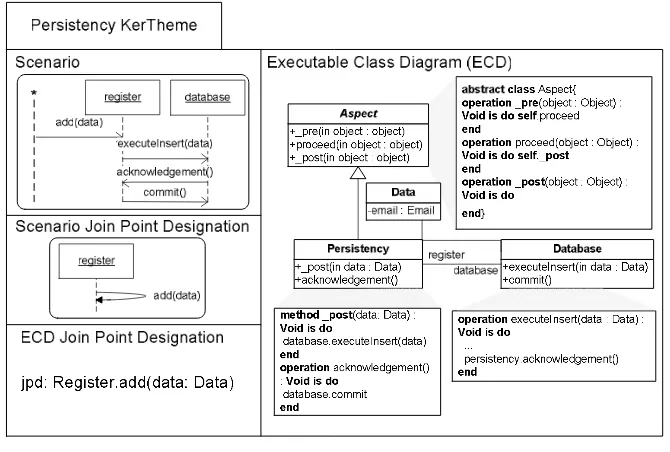
An aspect concern represents behaviors that are primarily crosscutting. Figure 2 illustrates a kerTheme model that represents the Persistency aspect concern from the auction system example. The Persistency kerTheme specifies
behavior that saves enrolment information to a database.
The Persistency kerTheme module contains a scenario and
an ECD. Both of which are associated with distinct join point designation specifications.
The Persistency ECD illustrated on the right side of
Figure 2 defines three main classes: Persistency, Aspect2 and Database. The Persistency class inherits
2 The
Aspect class is a library class and is not defined by the designer.
from the Aspect class. This flags that the Persistency
class contains behaviors that are crosscutting. In general, the class that inherits from Aspect is called the crosscutting class. The Persistency class contains a
_post method. In KerMeta a method overrides an
operation. The _post method overrides the _post
operation defined in the Aspect class. As illustrated in the
Aspect class KerMeta fragment, the Aspect class is an
abstract class that defines _pre, _proceed and _post
operations. These operations define how a join point is crosscut (before, around and after) and are overridden to specify crosscutting behavior. By overriding the _post
operation, we specify that any join point that is applied to
the Persistency kerTheme will execute Persistency
behavior after the join point has executed. The body of the
_post method, as we can see from the KerMeta fragment
connected to the Persistency class, specifies a call to
the executeInsert operation on an instance of the Database class. This operation inserts the data into the database and calls the Persistency.acknowledge
operation when successfully completed. Within the body of the acknowledge operation a call on the database to commit the data into the database is specified.
The bottom left hand compartment of the Persistency
kerTheme illustrates a join point designation that specifies selection criteria for join points that will be applied to the persistency behavior specified in the
Persistency._post method. The criteria specifies that
calls to an operation with a signature that matches
add(data : Data) on any instance of the Register class are considered join points during model execution.
The Persistency scenario is illustrated in the top left
compartment of the Persistency kerTheme presented in
Figure 2. This describes the expected behavioral flow when the Persistency model is executed. The scenario
[image:3.612.145.480.72.298.2]begins with a call to the add operation on a register
object from some object (represented as *). Subsequent calls to executeInsert, acknowledge and commit operations are executed after add to ensure the data argument to the add call is persisted.
The middle compartment on the left of the Persistency
kerTheme presented in Figure 2 illustrates a join point designation that specifies selection criteria for join points within the expected behavior represented in the scenario. These criteria specify that add operation calls made by a register object on itself are join points.
3
Base-Base Merging
The composition of base/base kerthemes is performed through a merging operator. Merge operator is a symmetric 1 to 1 composition operator (two base models). It is an operator that fusions two model elements that represent different views on the same concept (in both input models) into one new model element that represents the merge of those views. This section formalizes the merge operator for ECD and scenarios.
3.1 ECD Base-Base Merging
ECD composition involves the unification of common
elements in the ECDs being merged. The composition of ECDs is based on a generic merge framework proposed in previous work [4]. In this paper, we formalize this framework and show how to use it for base/base and aspect/base kertheme compositions. The merge framework provides a default merge behavior when “no conflicts” exist between ECDs to be merged. The default behavior defines directives which include:
• The members of classes with the same identifier should be unified into one composite class with this identifier. Identifier of each model element type is specified in Table 1.
• Members of the same identifier should be unified into a single representation
In the following, we present first the conflict detection, then we introduce a mechanism for conflict resolution. Finally, we detail the process for using the merge operator for ECDs.
a Conflict detection formalization
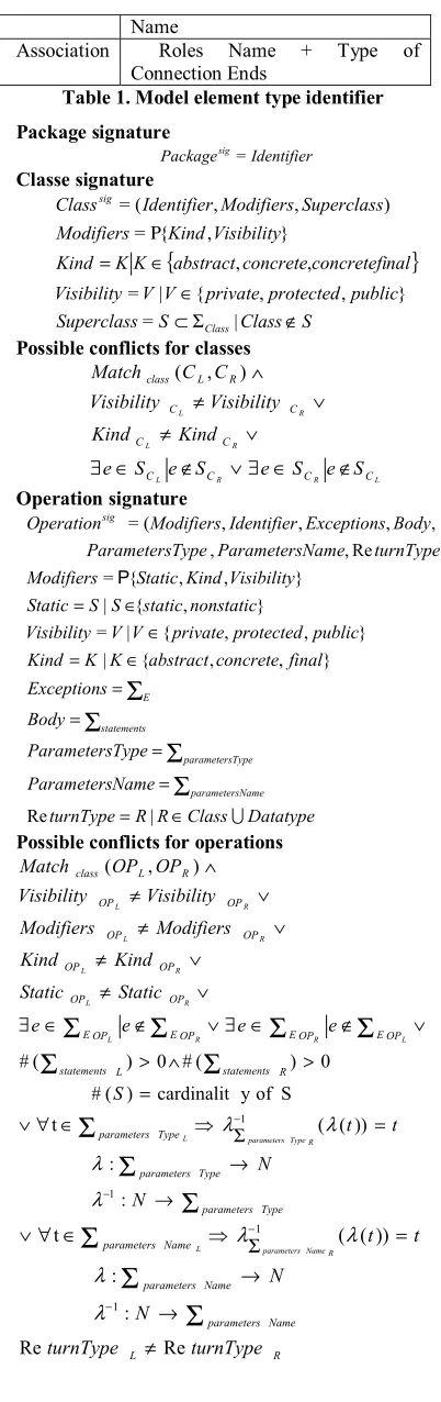
The conflict detection is based on the following mechanism. First, two elements that have the same identifier are detected (summed up in the Table 1). When two model elements have the same identifier, they form a candidate match. Next, the signatures of elements that match are compared. Each element has a signature which defines a strict equivalence between two model elements. When signatures of two matching elements are not equal, a conflict is detected. In the following, we define the signatures for each model elements and all possible conflicts. ∑type represents a set of typed model element.
Identifier Package Name
Class Name + Package Name
Method Name + Number of parameters + Class name + Package Name Property Name + Class name + Package
Name
[image:4.612.320.521.69.707.2]Association Roles Name + Type of Connection Ends
Table 1. Model element type identifier Package signature Identifier Packagesig = Classe signature
{
}
S Class S Superclass public protected private V V Visibility nal concretefi concrete abstract K K Kind Visibility Kind Modifiers Superclass Modifiers Identifier Class Class sig ∉ Σ ⊂ ∈ ∈ = Ρ | = } , , { | = , , } , { = ) , , ( =Possible conflicts for classes
L R R L R L R L C C C C C C C C R L class S e S e S e S e Kind Kind Visibility Visibility C C Match ∉ ∈ ∃ ∨ ∉ ∈ ∃ ∨ ≠ ∨ ≠ ∧ ) , ( Operation signature Datatype Class R R turnType Name Parameters Type Parameters Body Exceptions final concrete abstract K K Kind public protected private V V Visibility nonstatic static S S Static Visibility Kind Static Modifiers turnType Name Parameters Type Parameters Body Exceptions Identifier Modifiers Operation Name parameters Type parameters statements E sig ∪ ∈ = = = = = ∈ = ∈ ∈ =
Σ
Σ
Σ
Σ
| Re } , , { | } , , { | = } , { | } , , { = ) Re , , , , , , ( = PPossible conflicts for operations
∨ ≠ ∨ ≠ ∨ ≠ ∧ R L R L R L OP OP OP OP OP OP R L class Kind Kind Modifiers Modifiers Visibility Visibility OP OP
Match ( , )
Σ
Σ
Σ
Σ
Σ
Σ
Σ
Σ
Σ
Property signature Datatype Class R R Type final concrete abstract K K Kind public protected private V V Visibility nonstatic static S S Static Visibility Kind Static Modifiers Type Identifier Modifiers Psig ∪ ∈ = ∈ = ∈ ∈ = | } , , { | } , , { | = } , { | } , , { = ) , , ( = P
Possible conflicts for properties
R L P P OP OP P P P P R L class Type Type Static Static Kind Kind Modifiers Modifiers Visibility Visibility P P Match R L R L R L R L ≠ ∨ ≠ ∨ ≠ ∨ ≠ ∨ ≠ ∧ ) , ( Association signature
}
{
}
{
{
}
{
}
Boolean Volatile Boolean Settable Boolean Derived Volatile Settable Derived xP Volatile Settable Derived P EndAttr Connection n compositio n aggregatio simple x n compositio n aggregatio simple EndKind Connection NxNxNxN icity EndMultipl Connection EndAttr Connection EndKind Connection icity EndMultipl Connection Identifier n Associatio sig = = = = = = , , , , , , , , ) , , , ( =Possible conflicts for associations
R L R L R L A A A A A A R L ns associatio EndAttr Connection EndAttr Connection EndKind Connection EndKind Connection icity EndMultipl Connection icity EndMultipl Connection A A Match ≠ ∨ ≠ ∨ ≠ ∧ ) , (
b Conflict resolution
The framework supports the resolution of conflicts that arise during composition. This resolution can be parameterized to allow the designer to define composition specifications that describe how specific conflicts should be resolved. The composition framework is based on a strategy design pattern [5] as illustrated in Figure 3. Resolution strategies for specific conflicts are encapsulated in modules called ConflictFixers which can be specified or extended and plugged into the framework. The role of ConflictFixers can be compared to the role of composition directives proposed by Straw et al. [6]. ConflictFixers are defined by implementing a model transformation that modifies the input models to suppress the conflict. ConflictFixers in this framework provide support for fine-grained parameterization of the merge operator that can be used to override the default semantics of the merge where and when appropriate.
Some predefined ConflictFixers can be used directly in the composition framework. For example, if the framework detects conflicts between visibility of properties that match. Designers can configure the framework to keep the more restrictive or less restrictive
visible property. Another merge parameterization consists to allow the merge of properties even if their types are not exactly the same. Those conflict fixers are defined below.
//different visibility //keep more restrictive
L R L R L PROP PROP PROP rty mergePrope Visibility Visibility ctive MoreRestri = ) , ( ) , ( ⇒
//keep less restrictive
R R L R L PROP PROP PROP rty mergePrope Visibility Visibility ctive MoreRestri = ) , ( ) , ( ⇒ //conforming types //keep more specific
(suggested by the UML metamodel)
L R L R L PROP PROP PROP rty mergePrope Type Type = ) , ( < ⇒ R R L R L PROP PROP PROP rty mergePrope Type Type = ) , ( > ⇒
//keep more generic
L R
L R
L Type mergePropertyPROP PROP PROP
Type > ⇒ ( , )=
R R
L R
L Type mergePropertyPROP PROP PROP
Type < ⇒ ( , )=
c Process for ECD base-base merging
Based on the conflict detection and resolution mechanisms, the process for merging ECDs is decomposed in four phases:
1. Designers implement specific composition semantics by implementing the interface ConflictFixers as presented in the Figure 3. This ConflictFixer consumes an exception through the method solveConflict. This exception provides two pieces of information: its type and two references on the model elements that are involved in the conflict.
2. Next, designers register their own ConflictFixer into the ConflictSolver.
3. ConflictFixers are used to resolve composition issues. To illustrate an example of composition issue, let us consider two classes (with the same signature) that both have concrete operations with signatures match. When the framework finds this composition issue, it raises an OverloadingOperationException as illustrated in Figure 4. A previously registered ConflictFixer: OverloadingOperationFixer modifies the ECDs to solve the conflict. Resolution can be achieved by renaming these operations in each ECD. Then a new operation is generated in one ECD that calls these methods in a defined order3. When, the ConflictFixer has fixed a conflict, it sets the isFixed property of the Exception to true. Then, the ConflictSolver tries to find other conflicts to solve.
4. When all conflicts have been detected and solved, the default merge behavior is applied.
Fig Figure 3. Composition framework structure
Figure 4. Framework behaviour 3.2 Sequence Diagram Base-Base Merging
The base-base SD merging mainly consists in the merge of one base behavior with the other at special points explicitly specified by the user. We identify three different kinds of base-base merge operators which can be useful for the user:
1. An amalgamated sum [7] which merges two SDs sharing common elements.
2. A sequential composition [8] which composes sequentially two SDs along their common lifeline. 3. An inclusion which includes a SD M1 in another SD
M2.
These three merge operators will be detailed below. To use the same notation for the three operators, the merging of two SDs M1 and M2 is denoted M1 f+g M2.
a The Amalgamated Sum
When two SDs depict different viewpoints of the same behavior, one feels the need for a merge operation that would glue the two scenarios to produce a result that contains both operands without creating copies of similar elements. This operator cannot be expressed by means of traditional composition operators. Consequently, we propose the use of a symmetric merge operator for SDs called amalgamated sum.
In Klein et al. [7], the amalgamated sum is initially defined using Message Sequence Charts (MSCs) [9], but since the semantics of UML 2.X SDs are largely inspired by MSCs, the scenario merger can be easily adapted to SD (a comparison of UML 2.x SD and MSCs is discussed by Haugen [10]).
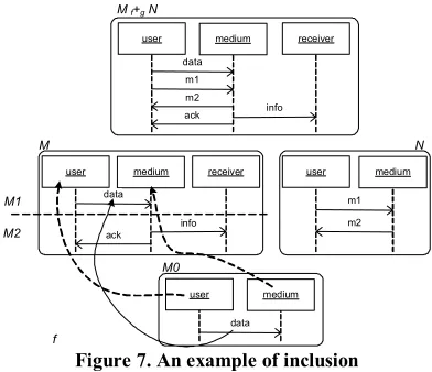
The main idea of an amalgamated sum of two SDs S1 and S2 is to yield a new SD S which is composed of the common elements of S1 and S2, plus the non-common elements of S1 and S2. The amalgamated sum of two SDs
S1 and S2 is denoted S1lf+g S2. The user has to specify a third SD S0, and two morphisms f (from S0 to S1) and g (from S0 to S2) to specify the common elements between S1 and S2.
In Figure 5, the SD M represents the result of the merge of M1 and M2. Considering M1 and M2 as two partial observations of the same system, we want to produce a behavior that contains M1 and M2. Let us also suppose that even if M1 and M2 have different object sets and some common messages with different name, the object user in M2 and the object sender in M1 represent the same object in the system, and the message ack in M1 and the message ok in M2 are the same. Intuitively, merging M1 and M2 then amounts to inserting the message work between data emission and ack reception in M1, and renaming the objects and the messages by keeping the names specified in M0.
Formally, the merge consists in the definition of an “interface” that identifies the common elements in M1 and M2 and renames them. For our example, this is done using a new SD M0 and two morphisms f:M0→M1 and g:M0→M2. The morphism f associates the objects user and medium of M0 to respectively the objects sender and medium of M1, but also the messages data and ack of M0 to respectively the messages data and ack of M1. The morphism g associates the objects user and medium of M0 to respectively the objects user and medium of M2, but also the messages data and ack of M0 to respectively the messages data and ok of M2. With f and g, an element e1 of M1 is identified as common with an element e2 of M2 whether e1 and e2 have the same antecedent by f and g, i.e., f-1(e1)=g-1(e2). Finally, we obtain the result M by adding the common elements of M1 and M2 by keeping the names specified in M0, then by adding the remaining elements of M1 and the remaining elements of M2.
Note that an amalgamated sum can yield SD with areas called coregion ([8], p. 485). A coregion is an area of a lifeline where the events (message emission or reception) are not ordered. For instance, if the message work of M2 in Figure 5 occurred on the object medium instead of the object user, the resulting SD M would contain a coregion between the messages data and ack on the object medium meaning that the message work and the sending of the message info are non-ordered.
sender medium data
ack
receiver
info
user medium data
ok work
user medium
data ack user medium
data
ack
receiver
info work
M1 M2
M
M0
[image:7.612.80.286.68.275.2]f g
Figure 5. Merge operator example M1 f+g M2
b The Sequential Composition
It is possible that the two SDs to merge do not share common elements (except the lifelines), and the user would simply like to order the SDs. In this case, the notion of sequential composition (noted ● or seq with the UML2 notation) is sufficient. Roughly speaking, sequential composition of two SDs consists of gluing both diagrams along their common lifelines. Note that the sequence operator only imposes precedence on events (message emission or reception) located on the same lifeline, but that events located on different lifelines in two SDs M1 and M2 can be concurrent in M1●M2.
sender medium
data ack
receiver
info
sender medium data
ok work
M1 M2
sender medium data ack
receiver
info M1 1+2 M2
data
ok work
sender medium data
ack
receiver
info M1 2+1 M2
[image:7.612.322.518.93.262.2]data ok work
Figure 6. Examples of Sequential Composition
To use the same notation as the amalgamated sum and to propose a symmetric operator, the sequential composition of a SD M1 with a SD M2 will be noted: M1 1+2 M2 (= M2 2+1 M1 = M1● M2). The morphisms f and g are simply replaced with the numbers 1 and 2, the number 1 indicating the behavior which occurs in first. Examples of sequential composition are depicted in Figure 6. c The Inclusion
The inclusion operator allows the inclusion of a SD N in another SD M at points explicitly specified by the user. The inclusion of N (called the included SD) in M (called the target SD) is noted M f+g N, where the morphism associated to the included SD (g in our case) is a “null” morphism. The user has to specify a third SD M0, and a
morphism from M0 to the target SD (f in our case) to specified the place where N has to be included.
user medium
data
ack
receiver
info
user medium
m1 m2
user medium
data
user medium
data
ack
receiver
info
M N
M f+g N
M0
f
m1 m2
M1
M2
Figure 7. An example of inclusion
Figure 7 shows an example of the inclusion of the SD N in the SD M. The morphism f allows the decomposition of M in two SDs M1 and M2 such as M=M1●M2. More specifically, M1 contains all the messages associated by f, and all the messages which precede the messages associated by f. Then, N is inserted between M1 and M2, and the result of the inclusion is M1●N●M2. In other words, f indicates the messages after which N has to be inserted.
Formally, f defines a cut of SD [11]. A cut partitions a SD M into two SDs M1 and M2. The cut is a valid cut whether the two SDs M1 and M2 are well-formed, i.e., a valid cut of a SD M is a cut that allows to partition M without cutting any messages.
4
Aspect-Base Weaving
The aspect/base kerTheme composition is not exactly of the same nature than the base/base kerTheme composition. This composition is based on a weaving operator. This is an asymmetric 1-n composition operator (one aspect model and n elements in the base model) that enhances the behaviour of n model elements in the source model with an additional behaviour modelled in the aspect model.
Generally, the weaving process is decomposed into two phases: (1) a phase of detection, where a part of an aspect (called pointcut) is used as a predicate to find all the areas in a base model where the aspects have to be woven; and (2) a phase of composition, where a second part of the aspect (called advice) is composed in the base model at the previously detected areas (called join points).
[image:7.612.86.287.398.517.2]aspect-oriented technology, but most of the solutions proposed so far are too tied to the syntax of the programs manipulated.
This section formalizes the weaving operator for the composition of ECDs and scenarios.
4.1 ECD Aspect-Base Weaving
The ECD aspect/base kerTheme composition is more complex than the ECD base/base kerTheme composition defined in Section 3.1. This composition operation is an extension of the merge framework presented in Section 3.1. When designers define an aspect kerTheme, they do not know the base kerTheme to which it will be applied. The Aspect class contains operations which define how a selected join point is crosscut (before, around or after).
For example, in the Persistency example, a call to the
[image:8.612.316.523.120.477.2]database is performed after the join point as illustrated in Figure 2. When the join points are selected with a join point designation expression, the weaving is a transformation process performed in five steps.
1. First the Aspect class in the aspect kerTheme is flattened with the crosscutting class (the Persistency class in the example of Section 3.3). Flattening is the process of removing the Aspect class which is merely a placeholder for specifying when crosscutting behaviors should execute at a join point. This flattening step results in one class containing the (pre, post, proceed) crosscutting operations of the Aspect class
that are not overridden. In our example, the persistency class contains a pre, proceed and post operation.
2. Next, join points are selected from base kerThemes by the ECD join point designator. For each join point selected, a copy of the crosscutting class is generated. This generated class is renamed with the name of the class in which the join point operation is defined. In our example, the Persistency class is named to Register as the join point operation is defined on the Register class. The _pre, _proceed and _post
operations in this class are also renamed. The join point operation name is appended to _pre and _post
operations and replaces “proceed” in the _proceed
operation. _pre is renamed to the name of the join
point named X in the rest of this section. The _proceed is renamed to _X. The _post operation is
renamed to _postX. In our example, the crosscutting class contains at least three operations: X (old pre), _X
(proceed), postX (old post). At this point, the aspect
kerTheme has become a base kerTheme and the process of base kerTheme composition begins.
3. The third step represents the first conflict resolution phases. The merge operator is used. A conflict is detected between both operations X of the aspect class
and the join point class. A fixer renames both operations. The join point operation is renamed by prepending an underscore to the start of its name. The old pre operation is now renamed to _preX. The fixer
creates a new operation named X that calls first _preX
and next _X. In our example. Both add operations are
renamed in preAdd and _Add. A new operation add is
created that calls first preAdd and next _Add.
4. The fourth step is the second conflict resolution phases. In this step a conflict is detected between both operations _X of the aspect class and the join point
class. In our example, a conflict is detected between both _Add operations. A fixer renames both operations
and creates a new one that calls first the operation _X
of the join point class and next the operation _X of the
aspect class. In our example, it renames the first _Add
operation in UI&Enroll_add, the second one in Persistency_add operation. It creates a new one
name _Add that calls the operation UI&Enroll_add
and next the Persistency_add. The
Persistency_add represents the old proceed
operation, it calls the _postadd operation. Other fixers
can adapt the models if other operations or properties are in conflict.
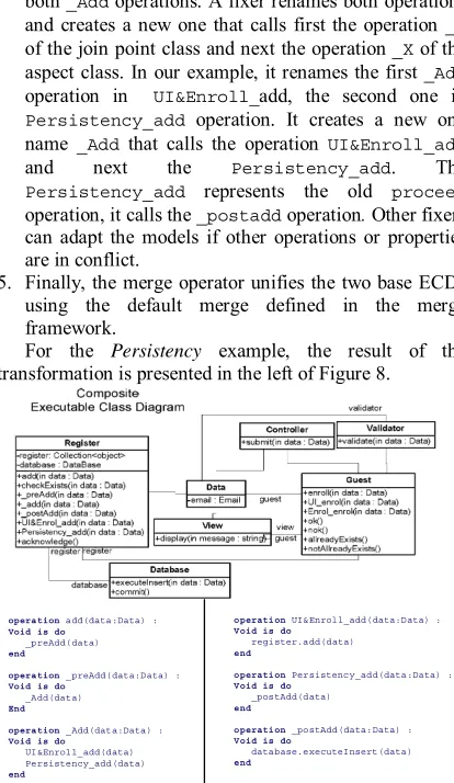
5. Finally, the merge operator unifies the two base ECDs using the default merge defined in the merge framework.
For the Persistency example, the result of the
[image:8.612.319.522.301.478.2]transformation is presented in the left of Figure 8.
Figure 8. UI&Enrol&Persistency KerTheme
4.2 Sequence Diagram Aspect-Base Weaving For weaving base and aspect scenarios, we use the semantic-based scenario weaver proposed in our previous work [14], where the weaving is based on the dynamic semantics of the models used. The scenarios are modeled with Message Sequence Charts (MSCs), but the scenario weaver can be easily adapted to SD as shown in [15].
With this scenario weaver, an aspect is defined as a pair of SDs, one SD for the pointcut (specification of the behavior to detect), and the second one for an advice representing the expected behavior at the join point. Similarly to Aspect-J, where an aspectual behavior can be inserted ’around’, ’before’ or ’after’ a join point, an advice may indifferently complete the matched behavior, replace it with a new behavior, or remove it entirely to create composed behavior. More formally, the composition of the advice in the base model at the join point is just a
operation add(data:Data) : Void is do
_preAdd(data) end
operation_preAdd(data:Data) : Void is do
_Add(data) End
operation_Add(data:Data) : Void is do
UI&Enroll_add(data) Persistency_add(data) end
operationUI&Enroll_add(data:Data) : Void is do
register.add(data) end
operationPersistency_add(data:Data) : Void is do
_postAdd(data) end
operation_postAdd(data:Data) : Void is do
replacement of the detected behavior with the advice. Indeed, when a join point (noted JP) is detected in a SD M, M can be written as M=M1●JP●M2. Then, the composition consists in the replacement of JP with the advice (noted Ad), and we obtain the woven SD Mw=M1●Ad●M2. Note that when an aspect is defined with sequence diagrams, some advantages related to sequence diagrams are preserved. In particular, it is easy to express a pointcut as a sequence of messages.
An example of this approach is presented in Figure 9. The base SD represents a customer log on a server. The customer tries to log in but he fails. The server answers to try again and the customer makes a new attempt which either succeeds or fails. The aspect specified in Figure 9 consists of the pointcut and the advice. For each message exchange starting with the message log_in() between an user and a server, the SD weaver adds the message notify() and the message update() on an object of type Display. The result of the weaving is depicted in Figure 10.
:User :Server
* Pointcut
log_in()
:Server :User
:Display
* Advice
update() notify() log_in() :User :Server
log_in() Base Sequence Diagram
try_again() log_in()
rejected() logged_in() alt
*
*
Figure 9. A base and an aspect Sequence Diagram
:User :Server
log_in()
try_again()
log_in()
rejected() logged_in() alt
:Display
update() notify()
update() notify()
[image:9.612.82.285.279.533.2]update() notify()
Figure 10. Result of the weaving
One of the difficulties in weaving SDs is that dynamic behavior needs to be woven at modeling time. Therefore, we need to statically find where the join points are in the base behavior. While this can be trivially implemented with a syntactic match for simple SDs, the hierarchical nature of UML 2.0 SD (similar to HMSCs [9]) makes it necessary to address the problem at the semantic level [14] with static analysis techniques such as loop unrolling, etc.
Klein et al.[15] propose a weaver that has been extended to facilitate the weaving of several aspects at a same join point. For that, a new interpretation for pointcuts has been proposed to allow join points to match them more flexibly, the idea being to allow join points to match a pointcut even when some extra-messages occur in between.
However, with this new way of specifying join points, the composition of the advice with the detected part could not any longer be a replacement of the detected part by the advice. The events (or the messages) of the join point which are not specified within the pointcut thus had to be considered and composed with the behavior specified within the advice. A new formal definition for such a composition operator, called left amalgamated sum, has been proposed [15]. The left amalgamated sum of two SDs M1 and M2 is denoted M1 f|+g M2. It is inspired by the amalgamated sum described in Section 3, but with f|+g, the left operand (usually the base SD) has not the same role as the right operand (usually the aspect SD). Consequently, the left amalgamated sum is no longer a symmetric (or commutative) composition operator. We call base SD and aspect SD respectively the left and right operand of the left amalgamated sum
As with the amalgamated sum, the common elements between the base and aspect SDs are identified with two morphisms and a third SD. But contrary to the amalgamated sum where the names of the common elements are defined by the names of the elements of the “interface” M0, with the left amalgamated sum, the names of the common elements are defined by the names of the elements of the base SD. Moreover, except for the common elements, the events (or the messages) of the aspect SD will always form a “block” around which the events of the base SD will be added. More details on the left amalgamated sum can be found in our previous work [15].
5
Related Work
In the Aspect Oriented Modeling, the composition of the different concern models identified in the early stage of the development process is an important issue when building a model with aspects. Main works consist in being able to compose UML diagrams. For example, France et al [16] have developed a systematic approach for composing class diagrams in which a default composition procedure based on name matching can be customized by user-defined composition directives. These directives constrain how class diagrams are composed. The framework identifies automatically conflicts between models that have to be composed and it solves them thanks to the composition directives. Composition directives address the weaving only from the structural point of view. It considers the composition as a model transformation. Besides, it is a symmetric AOM approach in which they do not differentiate between aspect and base. Consequently, they do not provide currently a pointcut language to manage the composition. Finally, they only manage the composition of the class diagram structure.
according to alternative and coherent ordering rules. However, as model composition directive, their work can only compose class diagram and can not compose dynamic diagram. Besides, they use a symmetric approach mainly used to design functional aspect. It can be difficult to model an aspect that crosscut several parts of the system.
Less connected with UML, Roberto Lopez-Herrejon et al [18] proposed an approach based on algebraic foundations. In their work, aspects are seen as a "program/model transformation function", or a function that maps programs/models to programs/models, and the effects of the weaving process can be understood in terms of algebraic transformations. Around this definition, theoretical properties (commutativity, associativity and identity) are assigned to aspect compositions, and rules are generated (in ex. precedence rules for compositions). This allows to reason about composition, exposing its problems and leading to a partial solution for aspect reusability and problems that derive from the weaving process. The kertheme composition operator can be seen as a practical approach of this problem.
In the same idea, several works consider model composition as a kind of model transformation (e.g. Baudry et al. [19]). In the model transformation domain, the correctness of the transformation is often a critical issue. Then, the aim of the different approaches presented in this section is to safely compose model. KerTheme, by providing a parallel composition operator provides a way to validate the composition.
6
Conclusion and Perspective
In this paper we have proposed four model composition operator in the context of the KerTheme approach for aspect-oriented modeling. This approach models separate concerns as kerThemes that are defined with two views: an executable class diagram that models the structure and the behavior of objects in a concern; a scenario that models the interactions between objects in a concern. We have defined two merge operators for composing the ECDs and scenarios of two base kerThemes. We have also defined a weaving operator that composes the ECDs and scenarios of an aspect and a base kerTheme.
In our future work, we want to run empirical studies to validate these composition operators. Then we plan to study the testability of the kerTheme models. Indeed, the two views for each kerTheme provide the necessary basis for checking the consistency between these views through testing. The composition operators are prerequisite for the testing activity since it is necessary to build a global view on the system’s model for validation.
7
References
1. A. Jackson, J. Klein, B. Baudry, and S. Clarke.
KerTheme: Testing Aspect Oriented Models. In
Proceedings of IMDT workshop in conjunction with
ECMDA'06. Bilbao, Spain, 2006.
2. S. Clarke and E. Baniassad, Aspect-Oriented Analysis
and Design. The Theme Approach. Addison-Wesley, Object Technology Series. 2005.
3. P.-A. Muller, F. Fleurey, and J.-M. Jézéquel. Weaving
executability into object-oriented meta-languages. In
Proceedings of MoDELS'05, p. 264 - 278. Montego
Bay, Jamaica, October 2005.
4. A. Jackson, O. Barais, J.-M. Jézéquel, and S. Clarke.
Towards a Generic and Extensible Merge Operator. In
Proceedings of Workshop on Models and Aspects in
conjunction with ECOOP 2006. Nantes, France, 2006.
5. E. Gamma, R. Helm, R. Johnson, and J. Vlissides,
Design Patterns: Elements of Reusable Object-Oriented Software. Professional Computing. 1995: Addison-Wesley.
6. G. Straw, G. Georg, E. Song, S. Ghosh, R. France, and
J.M. Bieman. Model Composition Directives. In
Proceedings of UML'04 (Unified Modeling Language), p. 84-97. Lisbon, Portugal, October 2004.
7. J. Klein, B. Caillaud, and L. Hélouët. Merging
scenarios. In Proceedings of FMICS (International Workshop on Formal Methods for Industrial Critical Systems), p. 209--226. Linz, Austria, September 2004.
8. OMG, UML Superstructure Specification, v2.1.1, OMG
Document number formal/07-02-05, 2007. 2007.
9. ITU-TS, ITU-TS Recommendation Z.120: Message
Sequence Chart (MSC). 1999: ITU-TS.
10. O. Haugen. Comparing UML 2.0 Interactions and
MSC-2000. In Proceedings of SAM 2004: SDL and MSC Fourth International Workshop, p. 69-84, 2004.
11. L. Hélouët and P. Le Maigat. Decomposition of
Message Sequence Charts. In Proceedings of SAM (Conference on SDL and MSC), 2000.
12. R.E. Tarjan, Depth-first search and linear graph
algorithms. SIAM Journal of Computer, 1972. 1(2): p. 146-160.
13. G. Kiczales. The Fun Has Just Begun. In Proceedings
of AOSD’03 (Int. Conf. on Aspect-oriented software development), 2003.
14. J. Klein, L. Helouet, and J.-M. Jézéquel.
Semantic-based Weaving of Scenarios. In Proceedings of
AOSD’06 (Int. Conf. on Aspect-oriented software development). Bonn, Germany, 2006.
15. J. Klein, F. Fleurey, and J.-M. Jézéquel, Weaving
multiple aspects in sequence diagrams. Trans. on Aspect Oriented Software Development, 2007.
16. R. Reddy, S. Ghosh, R. France, G. Straw, J.M. Bieman,
N. McEachen, E. Song, and G. Georg, Directives for Composing Aspect-Oriented Design Class Models.
Trans. on Aspect Oriented Development, 2006. 1(1): p. 75-105.
17. A. Muller, O. Caron, B. Carré, and G. Vanwormhoudt.
On Some Properties of parametrized Model Application. In Proceedings of ECMDA'0. Nuremberg, Germany, November 2005.
18. R. Lopez-Herrejon, D. Batory, and C. Lengauer. A
disciplined approach to aspect composition. In
Proceedings of ACM SIGPLAN symposium on Partial
evaluation and semantics-based program manipulation, p. 68 - 77. Charleston, SC, USA, 2006.
19. B. Baudry, F. Fleurey, R. France, and R. Reddy.