52
2
A HOMEMADE FALLOUT METER, THE KFM
z
r;
HOW TO MAKE AND USE IT
gv!
5
-I. The Need for Accurate and Dependable Fallout Meters II. Survival Work Priorities During a Crisis
If a nuclear war ever strikes the United States, survivors of the blast and fire effects Before building a KFM, persons expecting a nuclear attack within a few hours or would need to have reliable means of knowing when the radiation in the days and already in the place where they intend to await attack should work with environment around their shelters had dropped enough to let them venture safely
outside. Civil defense teams could use broadcasts of surviving radio stations to
the following priorities: (1) build or improve a high-protection-factor shelter (if give listeners a general idea of the fallout radiation in some broadcast areas.
possible, a shelter covered with 2 or 3 feet of earth and separate from flammable However, the fallout radiation would vary widely from point to point and the
buildings); (2) make and install a KAP (a homemade shelter-ventilating pump) --measurements would be made too far from most shelters to make them accurate
if instructions and materials are available; (3) store at least 15 gallons of water for enough to use safely. Therefore, each shelter should have some dependable
each shelter occupant -- if containers are available; (4) assemble all materials for one or two KFM’s; and (5) make and store the drying agent (by heating wallboard method of measuring the changing radiation dangers in its own area. gypsum, as later described) for both the KFM and its dry-bucket.
During a possible nuclear crisis that was rapidly worsening, or after a nuclear attack, most unprepared Americans could not buy or otherwise obtain a fallout meter -- an instrument that would greatly improve their chances of surviving a nuclear war. The fact that the dangers from fallout radiation -- best expressed in terms of the radiation dose rate, roentgens per hour (R/hr) -- quite rapidly decrease during the first few days, and then decrease more and more slowly, makes it very important to have a fallout meter capable of accurately measuring the unseen, unfelt and changing fallout dangers. Occupants of a fallout shelter should be able to control the radiation doses they receive. In order to effectively control the radiation doses, a dependable measuring instrument is needed to determine the doses they receive while they are in the shelter and while they are outside for emergency tasks, such as going out to get badly needed water. Also, such an instrument would permit them to determine when it is safe to leave the shelter for good.
III. How to Use These Instructions to Best Advantage
1. Read ALOUD all of these instructions through Section VII, “Tools Needed,” before doing anything else.
2. Next assemble all of the needed materials and tools.
3. Then read ALOUD ALL of each section following Section VII before beginning to make the part described in that section. 2
=I
Untrained families, guided only by these written instructions and using only low cost materials and tools found in most homes, have been able to make a KFM by working 3 or 4 hours. By studying the operating sections of these instructions for about 1 1/2 hours, average untrained families have been able to successfully use this fallout meter to measure dose rates and to calculate radiation doses received, permissible times of exposure, etc.
A FAMILY THAT FAILS TO READ ALOUD ALL OF EACH z SECTION DESCRIBING HOW TO MAKE A PART, BEFORE
BEGINNING TO MAKE THAT PART, WILL MAKE AVOID- ? ABLE MISTAKES AND WILL WASTE TIME. wh)
The KFM (Kearny Fallout Meter) was developed at Oak Ridge National Laboratory. It is understandable, easily repairable, and as accurate as most civil defense fallout meters. In the United States in 1976 a commercially available ion chamber fallout meter that has as high a range as a K F M f o r g a m m a r a d i a t i o n d o s e - r a t e measurements retailed for $600.
4. Have different workers, or pairs of workers, make the parts they are best qualified to make. For example, a less skilled worker should start making the drying agent (as described in Section VIII) before other workers start making other parts. The most skilled worker should make and install the aluminum-foil leaves (Sections X and XI).
5. Give workers the sections of the instructions covering the parts they are to build--so they can follow the step-by-step instructions, checking off with a pencil each step as it is completed.
Before a nuclear attack occurs is the best time to build, test and learn how to use a KFM. However, this instrument is so simple that it could be made even after fallout arrives provided that all the materials and tools needed (see lists given in Sections V, VI, and VII) and a copy of these instructions have been carried into the shelter.
6. Discuss the problems that arise. The head of the family often can give better answers if he first discusses the different possible interpretations of some instructions with other family members, including teenagers.
A KFM is a simple electroscope fallout meter with which fallout radiation can be measured accurately. To use a KFM, an electrostatic charge must first be placed on its two separate aluminum-foil leaves. These leaves are insulated by being suspended separately on clean, dry insulating threads.
To take accurate readings, the air inside a KFM must be kept very dry by means of drying agents such as dehydrated gypsum (easily made by heating gypsum wallboard, “sheetrock”) or silica gel. (Do not use calcium chloride or other salt.) Pieces of drying agent are placed on the bottom of the ionization chamber (the housing can) of a KFM.
An electrostatic charge is transferred from a homemade electrostatic charging device to the two aluminum-foil leaves of a KFM by means of its charging-wire. The charging-wire extends out through the transparent plastic cover of the KFM. When the two KFM leaves are charged
electrostati-cally, their like charges (both positive or both negative) cause them to be forced apart. When fallout
gamma radiation (that is similar to X rays but more energetic) strikes the air inside the ionization chamber of a KFM, it produces charged ions in this enclosed air. These charged ions cause part or all of the electrostatic charge on the aluminum-foil leaves to be discharged. As a result of losing charge, the two KFM leaves move closer together.
,
To read the separation of the lower edges of the two KFM leaves with one eye, look straight down on the leaves and the scale on the clear plastic cover. Keep
the reading eye 12 inches above the SEAT. The KFM ----i-- _= should be resting on a horizontal surface. To be sure the reading eye is always at this exact distance, place the lower end of a 12-inch ruler on the SEAT, while the upper end of the ruler touches the eyebrow above the reading eye. It is best to hold the KFM can with one hand and the ruler with the other. Using a flashlight makes the reading more accurate.
[image:3.766.280.372.62.200.2]If a KFM is made with the specified dimensions and of the specified materials, its accuracy is automatically and permanently established. Unlike most radiation measuring instruments, a KFM never needs to be calibrated or tested with a radiation source, if made and maintained as specified and used with the following table that is based on numerous calibrations made at Oak Ridge National Labor-atory.
The millimeter scale is cut out and attached (see photo illustrations on the following page) to the clear plastic cover of the KFM so that its zero mark is directly above the two leaves in their discharged position when the KFM is resting on a horizontal surface. A reading of the separation of the leaves is taken by noting the number of millimeters that the lower edge of one leaf appears to be on, on one side of the zero mark on the scale, and almost at the same time noting the number of millimeters the lower edge of the other leaf appears to be on, on the other side of the zero mark. The sum of these two apparent positions of the lower edges of the two leaves is called a KFM reading. The drawing appearing after the photo illustrations shows the lower edges of the leaves of a KFM appearing to be 9 mm on the right and zero and 10 on the left, giving a KFM reading of 19 mm. (Usually the lower edges of the 2 leaves are not at the same distance from the zero mark.) 2 Z As will be fully explained later, the radiation dose rate is determined 2 by:
ps 1-G) TABLE USED TO FIND DOSE RATES (R/HR) Z! cn
1. charging and reading the KFM before wfWE”~WEE FROM ,eTw.m THE 11mmw3 ,WO”.? EXms”“.5KFY READINGS ;d
exposure; *MD WC *.$*0,yG *FTEI CX?os”“.C FOIL LEA “CS, ,~~“*IwoI*o- or;: D,FF: IN TIME INTERVAL OF AN EXPOSURE
R E A D - ,SSEC ,MIN 4MIN 16MIN 1HR. z 2. exposing it to radiation for a specified
time in the location where measure- INGS2 mm 6.2 1.6 0.4 0.1 0.03R/HR R/HR R/HR R/HR R/HR ment of the dose rate is needed -- when 4 mm 12. 3.1 0.8 0.2 0.06 outdoors, holding the KFM about 3 ft. 6 mm 19. 4.6 1.2 0.3 0.08
above the ground; 8 mm 2 5 . 6.2 1.6 0.4 0.10
10 mm 31. 7.7 2.0 0.5 0.13 12mm 37. 9.2 2.3 0.6 0.15
3. reading the KFM after its exposure; 14mm 43. 11. 2.7 0.7 0.18
4. calculating, by subtraction, the difference between the reading taken before exposure and the reading taken after exposure;
5. using this table to find what the dose rate was during the exposure -- as will be described later.
[image:3.766.277.360.253.392.2]To get a clearer idea of the construction and use of a KFM, look carefully at the following photos and read their captions.
A.
B.
An Uncharged KFM. The charging wire has been pulled to one side by its adjustment-thread. This
photo was taken looking s t r a i g h t d o w n a t t h e upper edges of the two f l a t , 8 - p l y a l u m i n u m leaves. At this angle the leaves are barely visible, hanging vertically side by side directly under the zero mark, touching each other and with their ends even. Their suspension-t h r e a d s i n s u l a suspension-t e suspension-t h e leaves. These threads are almost parallel and touch (but do not cross) each other where they extend over the top of the rim of the can.
Charging a KFM by a Spark-Gap Discharge from a Tape That Has Been Electrostatically Charged by Being Unwound Quickly. Note that the charged tape is moved so that its
surface is perpendicular to the charging-wire. The high-voltage electro-static charge on the un-wound tape (that is an i n s u l a t o r ) j u m p s t h e spark-gap between the tape and the upper end of the charging-wire, and then flows down the charging-wire to charge the insulated aluminum-foil leaves of the KFM. (Since the upper edges of the two leaves are 3/4 inch below the scale and this is a photo taken at an angle, both leaves appear to be under the right side of the scale.)
C.
D.
A Charged KFM. Note t h e s e p a r a t i o n o f t h e upper edges of its two
leaves. T h e charging-wire has been raised to an almost horizontal pos-ition so that its lower end is too far above the alu-minum leaves to permit electrical leakage from the leaves back up the charging-wire and into the outside air.
Also note the SEAT, a piece of pencil taped to the right side of the can, opposite the charging wire.
Reading a KFM. A 12-inch ruler rests on the SEAT and is held vert-ical, while the reader’s e y e b r o w t o u c h e s t h e upper end of the ruler. The lower edge of the right leaf is under 8 on the scale and the lower edge of the left leaf is under 6 on the scale, giving a KFM reading of 14.
INSTRUCTIONS, Page 5
f
214.h. ADJUSTMENT THREAD (NYLON IS BEST)
‘/.-I”. TAPE ,“ERTICAL,
REMOVABLE TRANSPARENTCOVER AND CHARGING WIRE
AND
mECURE bETAIL)
TO FIT OVER SEAT
ON CAN ‘/,-In. TAPE AROVNO EDGE OF SKIRT OF COVER
THREAD TIED TO TOP VIEW
TOGGLE (SMALL SLIVER (COVER AND CHARGING WIRE NOT SHOWN) OF WOOD =b in. LONG1
TAPE TOGGLE TO OUTSIDE OF CAN
t-kin.1 f % 248)
bOTTOM OF CAN INSIDE DAY 2 G/qG in.
V. Materials Needed 10. An ordinary wooden pencil and a small toothpick (or split a small sliver of wood).
A . F o r the KFM: (In the following list, when more than one alternative material is given, the best material is listed first.)
1. Any type metal can, approximately 2-9/16 inches in diameter inside and 2-7/8 inches high inside, washed clean with soap. (This is the size of a standard 8-ounce can. Since most soup cans, pop cans, and beer cans also are about 2-9/16 inches in diameter inside, the required size of can can also be made by cutting down the height of more widely available cans --as described in Section IX of these instructions.)
2.
3.
4.
5.
6.
7.
8.
9.
Standard aluminum foil -- 2 square feet. (In 1977, 2 square feet of a typical American aluminum foil weighed about 8.2 grams -- about 0.29 O Z.) (If only “Heavy Duty” or “Extra Heavy Duty” aluminum foil is available, make 5-ply leaves rather than 8-ply leaves of standard foil; the resultant fallout meter will be almost as accurate.)
Doorbell-wire, or other light insulated wire (preferably but not necessarily a single-strand wire inside the insulation) -- 6 inches.
Any type of lightweight thread (preferably but not necessarily nylon). (Best is twisted nylon thread; next best, unwaxed lightweight nylon dental floss; next best, silk; next best, polyester.) -- 3 feet. (Thread should be CLEAN, preferably not having been touched with fingers. Monofilament nylon is too difficult to see, handle, and mark.)
A piece of clear plastic -- a 6 x 6 inch square. Strong polyethylene (4 mils thick) used for storm-proofing windows is best, but any reasonably stout and rather clear plastic will serve. The strong clear plastic used to wrap pieces of cheese, if washed with hot water and soap, is good. Do not use weak plastic or cellophane.
Cloth duct tape (“silver tape”), or masking tape, or freezer tape, or Scotch-type tape -- about 10 square inches. (Save at least 10 feet of Scotch Magic Transparent Tape for the charging device.)
Band-Aid tape, or masking tape, or freezer tape, or Scotch transparent tape, or other thin and very flexible tapes -- about 2 square inches.
Gypsum wallboard (sheetrock) -- about l/2 square foot, best about 1 / 2 inch thick. (To make the essential drying agent.)
Glue -- not essential, but useful to replace Band-Aid and other thin tapes. “One hour” epoxy is best. Model airplane cement is satisfactory.
11. Two strong rubber bands, or string. B. For the Charging Devices:
1. Most hard plastic rubbed on dry paper. This is the best method.
a. Plexiglas and most other hard plastics, such as are used in drafts-men’s triangles, common smooth plastic rulers, etc. -- at least 6 inches long.
b. Dry paper -- Smooth writing or typing paper. Tissue paper, news-paper, or facial tissue such as Kleenex, or toilet paper are satisfactory for charging, but not as durable.
2. Scotch Magic Transparent Tape (3/4 inch width is best), or Scotch 2 . Transparent Tape, or P.V.C. (Polyvinyl chloride) insulating electrical 2 tapes, or a few of the other common brands of Scotch-type tapes. (Some 2 plastic tapes do not develop sufficiently high-voltage electrostatic charges when unrolled quickly.) This method cannot be used for charging a KFM
2 inside a dry-bucket, needed for charging when the air is very humid.
5 5 C. For Determining Dose Rates and Recording Doses Received: 2 % 1. A watch -- preferably with a second hand. Q1 2. A flashlight or other light, for reading the KFM in a dark shelter or at
night.
3. Pencil and paper -- preferably a notebook.
D. For the Dry-Bucket: (A KFM must be charged inside a dry-bucket if the air is v e r y h u m i d , a s i t o f t e n i s i n s i d e a c r o w d e d , long-occupied shelter lacking adequate forced vent-ilation.)
1. A large bucket, pot, or can, preferably with a top diameter of at least 11 inches.
2. Clear plastic (best is 4-mil-thick clear plastic used for storm windows). A square piece 5 inches wider on a side than the diameter of the bucket to be used.
4.
5.
6.
7.
8.
Two plastic bags 14 to 16 inches in circumference, such as ordinary plastic bread bags. The original length of these bags should be at least 5 inches greater than the height of the bucket.
About one square foot of wall board (sheetrock), to make anhydrite drying agent.
Two l-quart Mason jars or other airtight containers, one in which to store anhydrite and another in which to keep dry the KFM charging devices. Strong rubber bands -- enough to make a loop around the bucket. Or string.
Four square feet of aluminum foil, to make a vapor-proof cover -- useful, but not essential.
VI. Useful but not Essential Materials --Which Could be Obtained Before a
Crisis--1. An airtight container (such as a large peanut butter jar) with a mouth at least 4 inches wide, in which to keep a KFM, along with some drying agent, when it is not being used. Keeping a KFM very dry greatly extends the time during which the drying agent inside the KFM remains effective.
2. Commercial anhydrite with a color indicator, such as the drying agent Drierite. This granular form of anhydrite remains light blue as long as it is effective as a drying agent. Obtainable from laboratory supply sources.
VII. Tools Needed Small nail - sharpened
Stick, or a wooden tool handle
(best 2 - 2 1/2 inch diameter and at least 12 inches long) Hammer
Pliers Scissors
Needle - quite a large sewing needle, but less than 2 1/2 inches long Knife with a small blade -- sharp
Ruler (12 inches)
VIII. Make the Drying Agent
-- The Easiest Part to Make, but Time Consuming
--For a KFM to measure radiation accurately, the air inside its ionization chamber must be kept very dry. An excellent drying agent (anhydrite) can be made by heating the gypsum in ordinary gypsum wallboard (sheetrock). Do NOT use calcium chloride.
Take a piece of gypsum wallboard approximately 12 inches by 6 inches, and preferably with its gypsum about 3/8 inches thick. Cut off the paper and glue, easiest done by first wetting the paper. [Since water vapor from normal air penetrates the plastic cover of a KFM and can dampen the anhydrite and make it ineffective in as short a time as two days, fresh batches of anhydrite must be made before the attack and kept ready inside the shelter for replacement. The useful life of the drying agent inside a KFM can be greatly lengthened by keeping the KFM inside an airtight container (such as a peanut butter jar with a 4-inch-diameter mouth) with some drying agent, when the KFM is not being
used.] 5Z
Y Break the white gypsum filling into small pieces and make the Z largest no more than l/2 in. across. (The tops of pieces larger “‘:-..‘. I+, 2 than this may be too close to the aluminum foil leaves.) If the jf/R.lny: gypsum is dry, using a pair of pliers makes breaking it easier.
D” s: 2 .:. 5 :
,7.:5.;. L’ E
Make the largest side of the largest pieces no bigger than this. v, ? Dry gypsum is not a drying agent. To drive the water out of the gypsum % molecules and produce the drying agent (anhydrite), heat the gypsum in an q oven at its highest temperature (which should be above 400 degrees F) for one hour. Heat the gypsum after placing the small pieces no more than two pieces deep in a pan. Or heat the pieces over a fire for 20 minutes or more in a pan or can heated to a dull red.
If sufficient aluminum foil and time are available, it is best to heat the gypsum and store the anhydrite as follows:
a.
b.
So that the right amount of anhydrite can be taken quickly out of its storage jar, put enough pieces of gypsum in a can with the same diameter as the KFM, measuring out a batch of gypsum that almost covers the bottom of the can with a single layer.
Cut a piece of aluminum foil about 8 in. x 8 in. square, and fold up its edges to form a bowl-like container in which to heat one batch of gypsum pieces.
C. Measure out 10 or 12 such batches, and put each batch in its aluminum foil “bowl.”
6.
7.
8.
e. As soon as the aluminum foil is cool enough to touch, fold and crumple the edges of each aluminum foil “bowl” together, to make a rough aluminum-covered “ball” of each batch of anhydrite.
f. Promptly seal the batches in airtight jars or other airtight containers, and keep containers closed except when taking out an aluminum-covered “ball.”
Since anhydrite absorbs water from the air very rapidly, quickly put it in a dry airtight container while it is still quite hot. A Mason jar is excellent.
To place anhydrite in a KFM, drop in the pieces one by one, being careful not to hit the leaves or the stop-threads. The pieces should almost cover the bottom of the can, with no piece on top of other pieces.
To remove anhydrite from a KFM, use a pair of scissors or tweezers as
forceps, holding them in a vertical position and not touching the leaves. IX. Make the Ionization Chamber of the KFM
(To Avoid Mistakes and Save Time,
Read All of This Section ALOUD Before Beginning Work.)
Remove the paper label (if any) from an ordinary 8-ounce can from which the top has been smoothly cut. Wash the can with soap and water and dry it. (An 8-ounce can has an inside diameter of about 2-9/16 inches and an inside height of about 2-7/8 inches.)
Skip to step 3 if an 8-ounce can is available. If an 8-ounce can is not available, reduce the height of any other can having an inside diameter of about 2-9/16 inches (such as most soup cans, most pop cans, or most beer cans). To cut off the top part of a can, first measure and mark the line on which to cut. Then to keep from bending the can while cutting, wrap newspaper tightly around a stick or a round wooden tool handle, so that the wood is covered with 20 to 30 thicknesses of paper and the diameter (ideally) is only slightly less than the diameter of the can.
One person should hold the can over the paper-covered stick while a second person cuts the can little by little along the marked cutting line. If leather gloves are available, wear them. To cut the can off smoothly, use a file, or use a hacksaw drawn backwards along the cutting line. Or cut the can with a sharp, short blade of a pocketknife by: (1) repeatedly stabbing downward vertically through the can into the paper, and (2) repeatedly making a cut about l/4 inch long by moving the knife into a sloping position, while keeping its point still pressed into the paper covering the stick.
Next, smooth the cut edge, and cover it with small pieces of freezer tape or other flexible tape.
3.
4.
5.
6.
Cut out the PAPER PATTERN TO WRAP AROUND KFM CAN. (Cut one pattern out of the following Pattern Page A.) Glue (or tape) this pattern to the can, starting with one of the two short sides of the pattern. Secure this starting short side directly over the side seam of the can. Wrap the pattern snugly around the can, gluing or taping it securely as it is being wrapped. (If the pattern is too wide to fit flat between the rims of the can, trim a little off its lower edge.)
Sharpen a small nail, by filing or rubbing on concrete, for use as a punch to make the four holes needed to install the stop-threads in the ionization chamber (the can). (The stop-threads are insulators that stop the charged aluminum leaves from touching the can and being discharged.)
Have one person hold the can over a horizontal stick or a round wooden tool-handle, that ideally has a diameter about as large as the dia-meter of the can. Then a second person can use the sharpened nail and a ham-mer to punch four very small holes through the sides of the can at the points shown by the four crosses on the pattern. Make these holes just large enough to run a needle through them, and then move the needle in the holes so as to bend back the obstructing points of metal.
PUNCH SMALL SHARPENED SMALL NAIL
HANDLE INSIDE
__---J
T h e s t o p - t h r e a d s c a n b e installed by using a needle to thread a single thread through all four holes. Use a very clean thread, prefer-ably nylon, and do not touch the parts of this thread that
TO NEEDLE SMALL TOGGLE TIED TO END OF THREAD TOGGLE THIS SMALL TlEDm 1/2 in. FROM CAN; LATER THREAD IS
will be inside the can and will serve as the insulating
STOP-stop-threads. Soiled threads THREAD are poor insulators.
(See illustrations.)
SIDE OF CAN
CUT EXACTL Y ON SIDE LINES \
$ H O L E G F O R
[image:9.775.74.685.58.481.2]STOP-T H R E A D
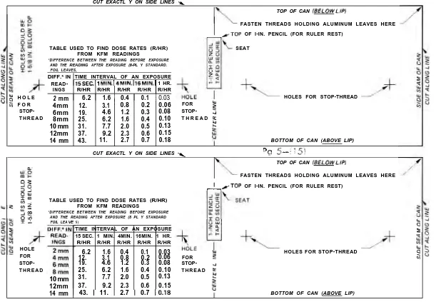
TABLE USED TO FIND DOSE RATES (R/HR) FROM KFM READINGS
‘DIFFERENCE BETWEEN THE READING BEFORE EXPOSURE AND THE READlNG AFTER EXPOSURE (8-PL Y STANDARD. FOIL LEAVES,
DIFF.* IN TIME INTERVAL OF AN EXPOSURE READ- 15SEC.11 MIN.14MIN.hGMIN.I 1 HR.
INGS R/HR R/HR R/HR R/HR R/HR
2 mm 1 6.2 1 1.6 1 0.4 1 0.1 1 0.03
4mm 12. 3.1 ~ 0.8 0.2 0.06
6mm 19. 4.6 1.2 0.3 0.08
8mm 25. 6.2 1.6 0.4 0.10
10 mm 31. 7.7 2.0 0.5 0.13 12mm 37. 9.2 2.3 0.6 0.15 14 mm 43. 11. 2.7 0.7 0.18
TOP OF CAN (BELOW LIP)
FASTEN THREADS HOLDING ALUMINUM LEAVES HERE
/TOP OF l-IN. PENCIL (FOR RULER REST)
SEAT
FOR 9
STOP- 2 T H R E A D a t!
HOLES FOR STOP-THREAD
BOTTOM OF CAN (ABOVE LIP)
CUT EXACTL Y ON SIDE LINES \ “9 5_-_!_g
TOP OF CAN IBELOWLIPI
FASTEN THREADS HOLDING ALUMINUM LEAVES HERE
03 gE: :i
tIz_
TABLE USED TO FIND DOSE RATES (R/HR) FROM KFM READINGS
w
$3
‘DIFFERENCE BETWEEN THE READING BEFORE EXPOSURE AND THE READING AFTER EXPOSURE (8 PL Y STANDARD FOIL LEA VE
1
-/TOP OF I-IN. PENCIL (FOR RULER REST)
HOLE FOR STOP-T H R E A D
10 mm 12mm 14 mm
S)
TIME INTERVAL OF AN EXPOSURE z
15 SEC. 1 MIN. 4MIN. 16MIN. 1 HR. s
R/HR R/HR R/HR R/HR R/HR
6.2 1.6 0.4 0.1 0.03 HOLES FOR STOP-THREAD :
12. 3.1 0.8 0.2 0.06 FOR 2 ci
19. 4.6 1.2 0.3 0.08
STOP-25. 6.2 1.6 0.4 0.10 T H R E A D :
31. 7.7 2.0 0.5 0.13 f!
37. 9.2 2.3 0.6 0.15
1 43. 1 11. 1 2.7 1 0.7 10.18 BOTTOM OF CAN (ABOVE LIP)
PAPER PATTERN TO WRAP AROUND KFM CAN (GLUE OR TAPE SECURELY TO CAN)
CUT OUT THESE PATTERNS, EACH OF WHICH IS THE EXACT SIZE FOR A KFM.
Before threading the thread through the four holes, tie a small toggle (see the preceding sketch) to the long end of the thread. (This toggle can easily be made of a very small sliver of wood cut about 3/8 in. long.) After the thread has been pulled through the four holes, attach a second toggle to the thread, about l/2 inch from the part of the thread that comes out of the fourth hole. Then the thread can be pulled tightly down the side of the can and the second small toggle can be taped securely in place to the side of the can. (If the thread is taped down without a toggle, it is likely to move under the tape.)
The first toggle and all of the four holes also should be covered with tape, to prevent air from leaking into the can after it has been covered and is being used as an ionization chamber.
pp d--(14)
X..
‘Make Two Separate 8-Ply Leaves of Standard[Not Heavy Duty*] Aluminum Foil
Proceed as follows to make each leaf: 1.
2.
3.
4.
5.
6.
Cut out a piece of standard aluminum
foil approximately 4 inches by 8 inches.
Fold the aluminum foil to make a 2-ply
(= 2 thicknesses) sheet approximately 4 inches by 4 inches.
Fold this 2-ply sheet to make a 4-ply s h e e t a p p r o x i m a t e l y 2 i n c h e s b y 4
inches. t
z THE SQUARE ka CORNER
8-PLY
SHEET
THIRD-FOLD EDGE
Fold this 4-ply sheet to make an 8-ply sheet (8 sheets thick) approximately 2 inches by 2 inches, being sure that the two halves of the second-fold edge are exactly together. This third folding makes an 8-ply aluminum foil sheet with one comer exactly square.
Cut out the FINISHED-LEAF PATTERN, found on the following Pattern Page B. Note that this pattern is NOT a square and that it is smaller than the 8-ply sheet. Flatten the 8 thicknesses of aluminum foil with the fingers until they appear to be a single thin, flat sheet.
Hold the FINISHED-LEAF PATTERN on top of the 8-ply aluminum foil sheet, with the pattern’s THIRD-FOLD EDGE on top of the third-fold edge of the 8-ply a l u m i n u m s h e e t . Be sure that one lower c o r n e r of the FINISHED-LEAF PATTERN is on top of the exactly square corner of the 8-ply aluminum sheet.
7.
8.
9.
10.
11.
While holding a straight edge along the THREAD LINE of the pattern, press with a sharp pencil so as to make a shallow groove for the THREAD LINE on the 8-ply aluminum sheet. Also using a sharp pencil, trace around the top and side of the pattern, so as to indent (groove) the 8-ply foil. Remove the pattern, and cut out the 8-ply aluminum foil leaf. While holding a straight edge a l o n g t h e i n d e n t e d T H R E A D LINE, lift up the OPEN EDGE of the 8-ply sheet (keeping all 8 plies together) until this edge is ver-tical, as illustrated. Remove the straight edge, and fold the 8-ply aluminum along the THREAD LINE so as to make a flat-folded hem.
Open the flat-folded hem of the finished leaf until the 8-ply leaf is almost flat again, as shown by the p a t t e r n , f r o m w h i c h t h e F I N -ISHED-LEAF PATTERN has al-ready been cut.
Prepare to attach the aluminum-foil leaf to the thread that will suspend it inside the KFM.
T H R E A D L I N E
-THE SQUARE CORNER OF 8-PLY SHEET
THIRD-FOLD EDGE OF 8-PLY SHEET
INSTRUCTIONS, Page 11
PATTERN FOR CLEAR-PLASTIC COVER FOR KFM CAN
THE PAPER SCALE TO
THE COVER OF CAN,
THE KFM LEAVES
SHORT SIDE
OPEN EDGE
CUT ALONG w
L3
THREAD LINE
ENDS OF MAR KS -IIII~IllI~llII~llII~llll~Illl~llIl~lIIl~llIl~Illl
3j ALSO CUT ON - 20 15 10 5 0 5 10 15 20
s!
THIS LINE
8-PLY LEAF
s
CUT ALONGENDS OF MARKS -
IIII~lIII~IIlI~IIII~IIIl~IIlI/IIII~IIIl~lIII/IIIl
THIRD-FOLD EDGE
ALSO CUT ON20 15 10 5 0 5 10 15 20
-THIS LINE
FINISHED-LEAF PATTERN
(CUT OUT EXACTLY ON SIDE LINES)
PAPER SCALE (TO BE CUT OUT)
CAUTION: XEROX COPIES OF THE FINISHED-LEAF AND THE
If no epoxy glue* is available to hold down the hem and prevent the thread from slipping in the hem, cut two pieces of tape (Band-Aid tape is best; next best is masking or freezer tape; next best, Scotch tape). After first peeling off the paper backing of Band-Aid tape, cut each piece of tape l/8 inch by 1 inch long. Attach these two pieces of tape to the finished 8-ply aluminum leaf with the sticky sides up, except for their ends. As shown by the pattern on the following pattern page, secure l/8 inch of one end of a tape strip near one corner of the 8-ply aluminum foil leaf by first turning under this l/8-inch end; that is, with this end’s sticky side down. Then turn under the other l/8-inch-long end, and attach this end below the THREAD LINE. Slant each tape strip as illustrated on Pattern (C).
Be sure you have read through step 18 before you do anything else. 12.
13.
14.
15.
16.
Cut an 8-l/2-inch piece of fine, unwaxed, very clean thread. (Nylon twisted thread, unwaxed extra-fine nylon dental floss, or silk thread are best in this order. Nylon monofilament “invisible” thread is an excellent insulator but is too difficult for most people to handle.)
Cut out Pattern (C), the guide sheet used when attaching a leaf to its suspending thread. Then tape Pattern (C) to the top of a work table. Cover the two “TAPE HERE” rectangles on Pattern (C) with pieces of tape, each piece the size of the rectangle. Then cut two other pieces of tape each the same size and use them to tape the thread ONTO the guide sheet, on top of the “TAPE HERE” rectangles.
Be very careful not to touch the two l-inch parts of the thread next to the outline of the finished leaf, since oil and dirt even on clean fingers will reduce the electrical insulating value of the thread between the leaf and the top rim of the can.
With the thread still taped to the paper pattern and while slightly lifting the thread with a knife tip held under the center of the thread, slip the finished leaf under the thread and into position exactly on the top of the leaf outlined on the pattern page. Hold the leaf in this position with two fingers.
While keeping the thread straight between its two taped-down ends, lower the thread so that it sticks to the two plastic strips. Then press the thread against the plastic strips.
With the point of the knife, hold down the center of the thread against the center of the THREAD LINE of the leaf. Then, with two fingers, carefully fold over the hem and press it almost flat. Be sure that the thread comes out of the corners of the hem. Remove the knife, and press the hem down completely flat against the rest of the leaf.
Make small marks on the thread at the two points shown on the pattern page. Use a ballpoint pen if available.
17.
18.
Loosen the second two small pieces of tape from the pattern paper, but leave these tapes stuck to the thread.
Cut 5 pieces of Band-Aid tape, each approximately
l/8 inch by l/4 inch, this small. n
Use 3 of these pieces of tape to secure the centers of the side edges of the leaf. Place the 5 pieces as illustrated in the SIDE VIEW sketch below.
ORNL DWG 76.6542
5 PIECES OF
I
1/8 IN. X 1/4 IN.
I 3
I
: AND LATER TO CAN m
SIDE VIEW END VIEW
SHOWING THE TWO LEAVES CHARGED (WHEN NOT CHARGED, T H E L E A V E S H A N G
PERPENDICULAR AND TOUCHING.)
*If using epoxy or other glue, use only a very little to hold down the hem, to attach the thread securely to the leaf and to glue together any open edges of the plied foil. Most convenient is “one hour” epoxy, applied with a toothpick. Model airplane cement requires hours to harden when applied between sheets of aluminum foil. To make sure no glue stiffens the free thread beyond the upper corners of the finished leaf, put no glue within l/4 inch of a point where thread will go out from the folded hem of the leaf.
The instructions in step 11 are for persons lacking “one hour” epoxy or the time required to dry other types of glue. Persons using glue instead of tape to attach the
COVER THE TWO "TAPE HERE" RECTANGLES WITH SAME-SIZED PIECES
OF TAPE, IN ORDER TO KEEP FROM TEARING THIS PAPER WHEN
REMOVING TWO ADDITIONAL PIECES OF TAPE. THEN, BY PUTTING
TWO OTHER PIECES OF TAPE THIS SAME SIZE ON TOP OF THE FIRST
TWO PIECES, TAPE THE THREAD ONTO THIS GUIDE SHEET, AND LATER
ATTACH A LEAF TO THE TAPED-DOWN THREAD.
IL
TAPE HERE TO HOLD THREAD SECURELY OVER THREAD LINE USE BALLPOINT PEN TO MARK THREAD HEREf
MARK THREAD HERE
TAPE T A P E J /- H E R E 4 THREAD LINE I I& , c / THREAD LINE HERE
DO NOT TOUCH DO NOT TOUCH OR MARK THIS
OF THREAD THIS I-INCH PART l-INCH PART
OF THE THREAD OF FINISHED L BAND-AID PLASTIC (1/8” X 1”) ALUMINUM-F0I L WITH STICKY SIDE UP AND
I
LEAFI ENDS FOLDED UNDER SO AS
DC;: %-(23
I 1 TO STICK TO ALUMINUM(OR USE A VERY LITTLE EPOXY.)
PATTERN (C)
(Cut out this guide along its border lines and tape to the top of a work table.)
4.
XI. Install the Aluminum-Foil Leaves 5.
Use the two small pieces of tape stuck to the ends of a leaf-suspending thread to attach the thread to the outside of the can. Attach the tapes on opposite sides of the can, so as to suspend the leaf inside the can. See END VIEW sketch. Each of the two marks on the attached thread MUST rest exactly on the top of the rim of the can, preferably in two very small notches filed in the top of the rim of the can. Each of these two marks on a thread should be positioned exactly above one of the two points shown on the pattern wrapped around the can. Be sure that the hem-side of each of the two leaves faces outward. See END VIEW sketch.
Next, the suspending thread of the first leaf should be taped to the top of the rim. Use a piece of Band-Aid only about l/8 in. x l/4 in., sticking it to the rim of the can so as barely to cover the thread on the side where the second leaf will be suspended. Make sure no parts of the tapes are inside the can.
Position and secure the second leaf, being sure that: a.
b.
C.
d.
e.
f.
g.
The smooth sides of the two leaves are smooth (not bent) and face each other and are flush (= “right together”) when not charged. See END VIEW sketch and study the first photo illustration, “An Uncharged K F M ” .
The upper edges of the two leaves are suspended side by side and at the same distance below the top of the can.
The leaf-suspending threads are taped with Band-Aid to the top of the rim of the can (so that putting the cover on will not move the threads).
No parts of the leaf-suspending threads inside the can are taped down to the can or otherwise restricted.
The leaf-suspending parts of the threads inside the can do not cross over, entangle or restrict each other.
The threads come together on the top of the rim of the can, and that the leaves are flat and hang together as shown in the first photo illustration, “An Uncharged KFM.”
If the leaves do not look like these photographed leaves, make new, better leaves and install them.
Cover with tape the parts of the threads that extend down the outside of the can, and also cover with more tape the small pieces of tape near the ends of the threads on the outside of the can.
6.
To make the SEAT, cut a piece of a wooden pencil, or a stick, about one inch long and tape it securely to the side of the can along the center line marked SEAT on the pattern. Be sure the upper end of this piece of pencil is at the same position as the top of the location for the SEAT outlined on the pattern. The top of the SEAT is 3/4 inch below the top of the can. Be sure not to cover or make illegible any part of the table printed on the paper pattern.
Cut out one of the “Reminders for Operators” and glue and/or tape it to the unused side of the KFM. Then it is best to cover all the sides of the finished KFM with clear plastic tape or varnish. This will keep sticky-tape on the end of an adjustment thread or moisture from damaging the “Reminders” or the table.
XII. Make the Plastic Cover
Cut out the paper pattern for the cover from the Pattern Page (B).
From a piece of clear, strong plastic, cut a circle approximately the same size as the paper pattern. (Storm-window polyethylene plastic, 4 mils thick, is best.)
Stretch the center of this circular piece of clear plastic over the open end of the can, and pull it down close to the sides of the can, making small tucks in the “skirt,” so that there are no wrinkles in the top cover. Hold the lower part of the “skirt” in place with a strong rubber band or piece of string. (If another can having the same diameter as the KFM can is available, use it to make the cover -- to avoid the possibility of disturbing the leaf-suspending threads.) Make the cover so it fits
snugly, but can be taken
I+ &-_!23\
r
COVERoff and replaced readily. (CLEAR
KEEP THIS SMALL PART PLASTIC)
Just below the top of the rim of the can, bind the covering plastic in place w i t h a l/4-inch-wide piece of strong tape. (Cloth duct tape is best. If only freezer or masking tape is available, use two thicknesses.)
Keep vertical the small p a r t o f t h e t a p e t h a t presses against the rim of the can while pulling the
OF THE 1/4 IN. TAPE VERTICAL Y
WHILE PULLING TAPE INSIDE AROUND RIM OF CAN OF CAN
RUBBER BAND
O R
-%: STRING
EDGE 1 OF PLASTIC I
COVER
INSTRUCTIONS
PAGE 15
REMINDERS FOR OPERATORS THE DRYING AGENT INSIDE A KFM
IS O.K.IF,WHEN THE CHARGED KFM IS NOT EXPOSED TO RADIA-TION, ITS READINGS DECREASE BY 1 MM OR LESS IN 3 HOURS. READING: WITH THE READING EYE 12 INCHES VERTICALLY ABOVE THE SEAT, NOTE ON THE MM SCALE THE SEPARATION OF THE LOWER EDGES OF THE LEAVES. IF THE RIGHT
LEAF IS AT 10 MM AND THE LEFT LEAF IS AT 7 MM, THE KFM READS 17 MM. NEVER TAKE A READING WHILE A LEAF IS TOUCHING A STOP-THREAD. NEVER USE A K F M READING THAT IS LESS THAN 5MM.
REMINDERS FOR OPERATORS FINDING HOW LONG IT TAKES TO THE DRYING AGENT INSIDE A KFM
GET A CERTAIN R DOSE: IF THEIS O.K.,= THE CHARGED DOSE RATE IS 1.6 R/HR OUTSIDE KFM IS NOT EXPOSED TO RADIA-AND A PERSON IS WILLING TO TION, ITS READINGS DECREASE TAKE A 6 R DOSE, HOW LONG CAN BY 1 MM OR LESS IN 3 HOURS. HE REMAIN OUTSIDE? ANSWER:
FINDING HO" LONG IT TAKES TO G E T A C E R T A I N R A I N DOSE RATE IS I"6 R/HR OUTSIh AND A PERSON IS WILLING TO TAKE A 6 R DOSE, HOW LONG CAN HE REMAIN OUTSIDE? ANSWER: 6 R + 1.6 R/HR = 3.75 HR = 3 HOURS AND 45 MINUTES.
FINDING A DOSE RATE: IF BEFORE
XPOSURE A KFM READS 17 MM AND IF AFTER A l-MINUTE EXPOSURE IT READS 5 MM, THE DIFFERENCE IN READINGS IS 12 MM, THE AT-TACHED TABLE SHOWS THE DOSE RATE WAS 9.6 R/HR DURING THE EXPOSURE.
FINDING A DOSE: IF A PERSON WORKS OUTSIDE FOR 3 HOURS WHERE THE DOSE RATE IS 2 R/HR, WHAT IS HIS RADIATION DOSE? ANSWER 3 HR x 2 R/HR = 6 R.
6 R + 1.6 R/HR = 3.75 HR = 3 HOURS AND 45 MINUTES. FALLOUT RADIATION GUIDES FOR
KIOUS-LY EXPOSED TO A TOTAL RADIA-TION DOSE OF MORE THAN 100 R DURING A 2-WEEK PERIOD 6 R PER DAY CAN BE TOLERATED FOR UP TO TW0 MONTHS WITHOUT
LOSING THE ABILITY TO WORK.
II
EXPOSURE A KFM RFINDING A DOSE RATE IF BEFORE EADSS 17 MM AND IF AFTER A l-MINUTE EXPOSURE 100 R IN A WEEK OR LESS IS NOT IT READS 5 MM, THE DIFFERENCE LIKELY TO SERIOUSLY SICKEN. IN READINGS IS 12 MM, THE AT-TACHED TABLE SHOWS THE DOSE 350 IN A FEW DAYS IS LIKELY RATE WAS 9.6 R/HR DURING THE TO PROVE FATAL UNDER POST- EXPOSURE.
ATTACK CONDITIONS.
FINDING A DOSE: IF A PERSON WORKS OUTSIDE FOR 3 HOURS 600 R IN A WEEK OR LESS IS
AKNIS CERTAIN TO CAUSE DEATH
WHERE THE DOSE RATE IS 2 R/HR, WHAT IS HIS RADIATION DOSE? WITHIN A FEW WEEKS. ANSWER 3 HR x 2 R/HR = 6 R.
FALLOUT RADIATION GUIDES FOR ~VIOUS-LY EXPOSED TO A TOTAL RADIA-TION DOSE OF MORE THAN 100 R DURING A 2-WEEK PERIOD: 6 R PER DAY CAN SE TOLERATED FOR UP TO TWO MONTHS WITHOUT LOSING THE ABILITY TO WORK. 100 IN A WEEK OR LESS IS NOT LIKELY TO SERIOUSLY SICKEN. 350 R IN A FEW DAYS IS LIKELY TO PROVE FATAL UNDER POST-ATTACK CONDITIONS.
EXACT SIZE
5. With scissors, cut off the “skirt” of the plastic cover until it extends only about one inch below the top of the rim of the can.
6. Make a notch in the “skirt,” about one inch wide, where it fits over the pencil SEAT attached to the can. The “skirt” in this notched area should be only about 5/8 of an inch long, measured down from the top of the rim of the can. 7. Remove the plastic cover, and then tape the lower edges of the “skirt,” inside
and out, using short lengths of l/4-inch-wide tape. Before securing each short piece of tape, slightly open the tucks that are being taped shut on their edges, so that the “skirt” flares slightly outward and the cover can be readily removed.
8. Put the plastic cover on the KFM can. From the Pattern Page (B) cut out the SCALE. Then tape the SCALE to the top of the plastic cover, in the position shown on the pattern for the cover, and also by the drawings. Preferably use transparent tape.
Be careful not to cover with tape any of the division lines on the SCALE between 20 on the right and 20 on the left of 0.
9. Make the charging-wire by following the pattern given below which is exactly the right size.
Doorbell wire with an outside diameter of about l/l6 inch is best, but any lightweight insulated wire, such as part of a lightweight two-wire extension cord split in half, will serve. The illustrated wire is much thicker than bell wire. To stop tape from possibly slipping up or down the wire, use a very little glue. r’Q r_ ,_I e Ir.
If a very thin plastic has been used for the cover, a sticky piece of tape may need to be attached to the end of the bare-ended adjustment thread, SO both
threads can be used to hold the charging wire in a desired position.
The best tape to attach to an end of one of the adjustment-threads is cloth duct tape. A square piece 3/4 inch by 3/4 inch is the sticky base. To keep this tape sticky (free of paper fibers), the paper on the can should be covered with transparent tape or varnish. A piece about l/8 inch by 3/4 inch serves to stick under one end of the sticky base, to hold the adjustment-thread. A 3/4 inch by l-1/4 inch rectangular piece of tape is used to make the finger hold --important for making adjustments inside a dry-bucket.
With a needle or pin, make a hole in the plastic cover l/2 inch from the rim of the can and directly above the upper end of the CENTER LINE between the
two leaves. The CENTER LINE is marked on the pattern wrapped around the can. Carefully push the CHARGING-WIRE through this hole (thus stretching the hole) until all of the CHARGING-WIRE below its Band-Aid-tape stop is inside the can.
TIE POINT FOR ONE THREAD
WHOSE TWO- BARE-ENDED
ENDS ARE THE U S T M E N T - T H R E A D
ADJUSTMENT-T H R E A D S
FINGER HOLD
TAPE SECUREL
I N S U L A T I O N BAND-AID-TAPE
L END OF 2-1/2 IN. T H R E A D THIS PART I N S U L A T I O N
GOES INSIDE STICKY-ENDED ADJUSTMENT-THREAD
THE KFM CAN (ACTUAL SIZE)
BARE WIRE vp p_ 7;
C H A R G I N G - W I R E
(= L~B”E1’,l~~~~~~B’E~RE’ S T I C K Y - E N D E D A D J U S T M E N T - T H R E A D
XIII. Two ways to Charge a KFM
1. Charging a KFM with Hard Plastic Rubbed on Dry Paper. a. Adjust the charging-wire so
that its lower end is about l/16 inch above the upper edges of the aluminum-foil leaves. Use the sticky-tape at the end of one adjust-ment-thread to hold the charging-wire in t h i s position. Stick this tape approximately in line with the threads suspending the leaves, either on the side of the can or on top of the p l a s t i c c o v e r . ( I f t h e charging-wire is held loose-ly by the cover, it may be necessary to put a piece of
sticky-tape on the end of each adjustment-thread in order to adjust the charging-wire securely. If a charging-wire is not secure, its lower end may be forced up by the like charge on the leaves before the leaves can be fully charged.)
b . Select a piece of Plexiglas, a draftsman’s plastic triangle, a smooth plastic ruler, or other piece of hard, smooth plastic. (Unfortunately, not all types of hard plastic can be used to generate a sufficient electrostatic charge.) Be sure the plastic is dry.
For charging a KPM inside a dry-bucket, cut a rectangular piece of hard plastic about 1-1/2 by 5 inches. Sharp corners and edges can be smoothed by rubbing on concrete. To avoid contaminating the charging end with sweaty, oily fingers, it is best to mark the other end with a piece of tape.
C. Fold DRY paper (typing paper, writing paper, or other smooth, clean paper) to make an approximate square about 4 inches on a side and about 20 sheets thick. (This many sheets of paper lessens leakage to the fingers of the electrostatic charges to be generated on the hard plastic and on the rubbed paper.)
d.
e .
f.
g.
Fold the square of paper in the middle, and move the h a r d plastic rapidly back and forth so that it is rubbed vigorously on the paper in the middle of this folded square -- while the outside of this folded square of p a p e r i s s q u e e z e d f i r m l y between thumb and the ends of two fingers.
discharging the charge on the plastic to the fingers, keep them away from the edges of the paper. See photo.
M o v e t h e e l e c t r o s t a t i c a l l y charged part of the rubbed plastic rather slowly past the upper end of the charging-wire, while looking straight down on the KFM. Keep the
hard plastic approximately perpendicular to the charging-wire and about 1/4 to 1/2 inch away from its upper end. The charge jumps the spark gaps and charges the leaves of the KFM.
Pull down on an insulating adjustment-thread to raise the lower end of the charging-wire. (If the charging-wire has been held in its charging position by its sticky-ended adjustment-thread being stuck to the top of the clear plastic cover, to avoid possibly damaging the threads: (1) pull down a little on the bare-ended adjustment-thread; and (2) detach, pull down on, and secure the sticky-ended adjustment-thread to the side of the can, so as to raise and keep the lower end of the charging-wire close to the underside of the clear plastic cover.) Do not touch the charging-wire.
Put the charging paper and the hard plastic in a container where they will be kept dry -- as in a Mason jar with some drying agent.
2. Charging a KFM from a Quickly Unwound Roll of Tape. (Quick unwinding produces a harmless charge of several thousand volts on the tape.)
b.
C.
d.
The sketch shows the “GET SET” position, preparatory to unrolling the Scotch Magic Transparent Tape, P.V.C. elec-trical tape, or other tape. Be sure to first remove the roll from its dispenser. Some of the other kinds of tape will not produce a high enough voltage.
QUICKLY unroll 10 to 12 inches of tape by pulling its end with the left hand. while the rieht hand allows the roll to unwind while remaining in about the same “GET SET” position only an inch or two away from the KFM.
“GET SET” POSITION \
While holding the unwound tape tight, about perpendicular to the charging-wire, and about l/4 inch away from the end of the charging-wire,
promptly move both hands and the tape to the right rather slowly -- taking about 2 seconds to move about 8 inches. The electrostatic charge on the unwound tape “jumps” the spark gaps from the tape to the upper end of the charging-wire and from the lower end of the charging-wire to the aluminum leaves, and charges the aluminum leaves.
Be sure neither leaf is touching a stop-thread.
Try to charge the leaves enough to spread them far enough apart to give a reading of at least 15 mm.
e. Pull down on an insulating adjustment-thread to raise the lower end of the
charging-wire. If the charging-wire has been held in charging position b y
its sticky-ended adjustment-thread being stuck to the top of the clear
plastic cover, it is best first to
p u l l d o w n a l i t t l e o n t h e
bare-ended adjustment-thread, and then to move, pull down on, and secure the sticky-ended adjustment-thread to the side of the can so that the lower part of the charging-wire is close to the underside of the clear plastic cover.
TRANSFERRlNG CHARGE
DO not touch the charging-wire.
f. Rewind the tape tight on its roll, for future use when other tape may not
be available. 2
XIV. Make and Use a Dry-Bucket
By charging a KFM while it is inside a dry-bucket with a transparent plastic cover (see illustration), this fallout meter can be charged and used even if the relative humidity is 100% outside the dry-bucket. The air inside the dry-bucket is kept very dry by a drying agent placed on its bottom. About a cupful of anhydrite serves very well. The pieces of this dehydrated gypsum need not be as uniform in size as is best for use inside a KFM, but do not use powdered anhy-drite.
A dry-bucket can be readily made in about an hour by proceeding as follows:
1. Remove the handle of a large bucket, pot, or can preferably with a top diameter of at least 11 inches. A 4-gallon bucket having a top diameter of about 14 inches is ideal. If the handle-supports interfere with stretching a piece of clear plastic film across the top of the bucket, remove them, being sure no sharp points remain.
2. Cut out a circular piece of clear plastic with a diameter about 5 inches larger than the diameter of the top of the bucket. Clear polyethylene 4 mils thick, used for storm windows, etc., is best. Stretch the plastic smooth across the top of the bucket, and tie it in place, preferably with strong rubber bands looped together to form a circle. 3. Make a plastic top that fits snugly but is easily removable, by taping over and around the plastic just below the top of the bucket. One-inch-wide cloth duct tape, or one-inch-wide glass-reinforced strapping tape, serves well. When taping, do not permit the lower edge of the tape to be pulled inward below the rim of the bucket.
i in.
-j 23/4 in.
j-A CENTER PIECE j-ABOUT l-l/Z in. BY 1 in. IS FIRST CUT OUT OF THE CLEAR PLASTIC COVER. THEN CUTS ARE MADE TO PRODUCE FLAPS, INDI CATED BY THE DOTTED
4.
5.
6.
7.
8.
9.
10.
11.
Cut two small holes (about 1 inch by 2 inches) in the plastic cover, as illustrated. Then make the radial cuts (shown by dotted lines) outward from the small holes, out to the solid-line outlines of the 3 inch by 4 inch hand-holes, so as to form small flaps.
Fold the small flaps upward, so they are vertical. Then tape them on their outer sides, so they form a vertical “wall” about 3/4 inch high around each hand-hole.
Reduce the length of two ordinary plastic bread bags (or similar plastic bags) to a length that is 5 inches greater than the height of the bucket. (Do not use rubber gloves in place of bags; gloves so used result in much more humid outside air being unintentionally pumped into a dry-bucket when it is being used while charging a KFM inside it.)
Insert a plastic bag into each hand-hole, and fold the edge of the plastic bag about l/2 inch over the taped vertical “wall” around each hand-hole.
Strengthen the upper parts of the plastic bags by folding 2-inch pieces of tape over the top of the “wall” around each hand-hole. Make about a quart of anhydrite by heating small pieces of wall-board gypsum, and keep this anhydrite dry in a Mason jar or other airtight container with a rubber or plastic sealer.
Make a circular aluminum-foil cover to place over the plastic cover when the dry-bucket is not being used for minutes to hours. Make this cover with a diameter about 4 inches greater than the diameter of the top of the bucket, and make it fit more snugly with an encircling loop of rubber bands, or with string. Although not essential, an aluminum-foil cover reduces the amount of water vapor that can reach and pass through the plastic cover, thus extending the life of the drying agent.
Charge a KFM inside a dry-bucket by:
a. Taking off wrist watch and sharp-pointed rings that might tear the plastic bags.
b. Placing inside the dry-bucket:
(1)
(2)
(3)
About a cup of anhydrite or silica gel;
the KFM, with its charging-wire adjusted in its charging position; and
dry, folded paper and the electrostatic charging device, best a 5-inch-long piece of Plexiglas with smoothed edges, to be rubbed between dry paper folded about 4 inches square and about 20 sheets thick. (Unrolling a roll of tape inside a dry-bucket is an impractical charging method.)
C. Replacing the plastic cover, that is best held in place with a loop of rubber bands.
d. Charging the KFM with your hands inside the plastic bags, operating the charging device. Have another person
illuminate the KFM with a flashlight. When adjusting the charging-wire, move your hands very slowly. See the dry-bucket photos.
12. Expose the KFM to fallout radiation either by:
a. Leaving the KFM inside the dry-bucket while exposing it to fallout radiation for one of the listed time intervals, and reading the KFM before and after the exposure while it remains inside the dry-bucket. (The reading eye should be a measured 12 inches above the SEAT of the KFM, and a flashlight or other light should be used.)
b. Taking the charged KFM out of the dry-bucket to read it, expose it, and read it after the exposure. (If this is done repeatedly, especially in a humid shelter, the drying agent will not be effective for many KFM chargings, and will have to be replaced.)
x v . How to Use a KFM after a Nuclear Attack A. Background Information
If during a rapidly worsening crisis threatening nuclear war you are in the place where you plan to take shelter, postpone studying the instructions following this sentence until after you have:
(1) built or improved a high-protection-factor shelter (if possible, a shelter covered with 2 or 3 ft of earth and separate from flammable buildings), and
(2) made a KAP (homemade shelter-ventilating pump) if you have the instructions and materials, and
(3) stored at least 15 gallons of water for each shelter occupant if you can obtain containers.
Most fortunately for the future of all living things, the decay of radioactivity causes the sandlike fallout particles to become less and less dangerous with the passage of time. Each fallout particle acts much like a tiny X ray machine would if it were made so that its rays, shooting out from it like invisible light, became weaker and weaker with time.
Contrary to exaggerated accounts of fallout dangers, the radiation dose rate from fallout particles when they reach the ground in the areas of the heaviest fallout will decrease quite rapidly. For example, consider the decay of fallout from a relatively nearby, large surface burst, at a place where the fallout particles are deposited on the ground one hour after the explosion. At this time one hour after the explosion, assume that the radiation dose rate (the best measure of radiation danger at a particular time) measures 2,000 roentgens per hour (2,000 R/hr) outdoors. Seven hours later the dose rate is reduced to 200 R/hr by normal radioactive decay. Two days after the explosion, the dose rate outdoors is reduced by radioactive decay to 20 R/hr. After two weeks, the dose rate is less than 2 R/hr. When the dose rate is 2 R/hr, people can go out of a good shelter and work outdoors for 3 hours a day, receiving a daily dose of 6 roentgens, without being sickened.
In places where fallout arrives several hours after the explosion, the radioactivity of the fallout will have gone through its time period of most rapid decay while the fallout particles were still airborne. If you are in a location so distant from the explosion that fallout arrives 8 hours after the explosion, two days must pass before the initial dose rate measured at your location will decay to 1/10 its initial intensity.
B. Finding the Dose Rate
1. Reread Section IV, “What a KFM Is and How It Works. ” Also reread Section XIII, “Two Ways to Charge a KFM,” and actually do each step immediately after reading it.
2. Charge the KFM, raise the lower end of its charging-wire and read the apparent separation of the lower edges of its leaves while the KFM rests on an approximately horizontal surface. Never take a reading while a leaf is touching a stop-thread.
3. Expose the KFM to fallout radiation for one of the time intervals shown in the vertical columns of the table attached to the KFM. (Study the following table.) If the dose rate is not known even approximately, first expose the fully charged KFM for one minute. For dependable measurements outdoors, expose the charged KFM about three feet above the ground. For most exposures, connect the KFM to a stick or pole (best done with two rubber bands), and expose it about three feet above the ground. Be careful not to tilt the KFM too much.
4. 5. 6. 7. 8. 9.
Read the KFM after the exposure, while the KFM rests on an approximately horizontal surface.
Find the time interval that gives a dependable reading -- by exposing the fully charged KFM for one or more of the listed
time intervals until the reading after the exposure is:
(a)
(b)
Not less than 5 mm.
At least 2 mm less than the reading before the
exposure.
Calculate by simple subtraction the difference in the apparent separation of the lower edges of the leaves before the exposure and after the exposure. An example: If the reading before the exposure is 18 mm and the reading after the exposure is 6 mm, the difference in readings is 18mm -6 mm = 12 mm.
If an exposure results in a difference in readings of less than
2 mm, recharge the KFM and expose it again for one of the
longer time intervals listed. (If there appears to be no difference in the readings taken before and after an exposure for one minute, this does not prove there is absolutely no fallout danger.)
If an exposure results in the reading after the exposure
being less than 5 mm, recharge the KFM and expose it
again for one of the shorter time intervals listed.
Use the table attached to the
KFM to find the dose rate
(R/hr) during the time of exposure. The dose rate
(R/hr) is found at the
TABLE USED TO FIND DOSE RATES (R/HR FROM KFM READINGS *DIFFERENCE BETWEEN THE READlNG BEFORE EXPOSURE
AND THE READING AFTER EXPOSURE (8-PLY STANDARD FOlL LEA VES)
DIFF.*IN TIME INTERVAL OF AN EXPOSURE R E A D - 15 SEC. 1 M I N 4 MIN 16 MIN 1 HR
INGS R/HR R/HR R/HR R/HR R/HR
2 m m 6 . 2 1.6 0.4 0.1 0 . 0 3 4 m m 12. 3.1 0 . 8 0 . 2 0 . 0 6 6 m m 19. 4 . 6 1.2 0.3 0 . 0 8 8 mm 25. 6 . 2 1.6 0.4 0 . 1 0 10 mm 31. 7 . 7 2 . 0 0.5 0 . 1 3 12 mm 37. 9 . 2 2.3 0 . 6 0 . 1 5 14 mm 4 3 . 11. 2.7 0 . 7 0 . 1 8 intersection of the vertical
column of numbers under the time interval used and of the horizontal line of num-bers that lists the calculated difference in readings at its left end.
An example: If the time interval of the exposure was 1 MIN. and the difference in readings was 12 mm, the
the table shows that the dose rate during the time interval of
the exposure was 9.2 R/HR (9.2 roentgens per hour).
Another example: If the time interval of the exposure was
15 SEC. and the difference in readings was 11 mm, the table
10.
11.
Note in the table that if an exposure for one of the listed time intervals causes the difference in readings to be 2 mm or 3 mm, then an exposure 4 times as long reveals the same dose rate. An example: If a l - min exposure results in a difference in readings of 2 mm, the table shows the dose rate was 1.6 R/hr; then if the KFM is exposed for 4 minutes at this same dose rate of 1.6 R/hr, the table shows that the resultant difference in readings is 8 mm.
T h e l o n g e r e x p o s u r e r e s u l t s i n a m o r e a c c u r a t e determination of the dose rate.
If the dose rate is found to be greater than 0.2 R/hr and time is available, recharge the KFM and repeat the dose-rate measurement -- to avoid possible mistakes.
C. Calculating the Dose Received
The dose of fallout radiation -- that is, the amount of fallout radiation received -- determines the harmful effects on men and animals. Being exposed to a high dose rate is not always dangerous -- provided the exposure is short enough to result in only a small dose being received. For example, if the dose rate outside an excellent fallout shelter is 1200 R/hr and a shelter occupant goes outside for 30 seconds, he would be exposed for 1/2 of 1 minute, or 1/2 of 1/60 of an hour, which equals 1/120 hour. Therefore, since the dose he would receive if he stayed outside for 1 hour would be 1200 R, in 30 seconds he would receive l/l20 of 1200, which equals 10 R (1200 R divided by 120 = 10 R). A total daily dose of 10 R (10 roentgens) will not cause any symptoms if it is not repeated day after day for a week or more.
In contrast, if the average dose rate of an area were found to be 12 R/hr and if a person remained exposed in that particular area for 24 hours, he would receive a dose of 288 R (12 R/hr x 24 hr = 288 R). Even assuming that this person had been exposed previously to very little radiation, there would still be a serious risk that this 288 R dose would be fatal under the difficult conditions that would follow a heavy nuclear attack.
Another example: Assume that three days after an attack the occupants of a dry, hot cave giving almost complete protection against fallout are in desperate need of water. The dose rate outside is found to be 20 R/hr. To backpack water from a source 3 miles away is estimated to take 2-1/2 hours. The cave occupants estimate that the water backpackers will receive a dose in 2-1/2 hours of 50 R (2.5 hr x 20 R/hr = 50 R). A dose of 50 R will cause only mild symptoms (nausea in about 10% of persons receiving a 50 R dose) for persons who previously have received only very small doses. Therefore, one of the cave occupants makes a rapid radiation survey for about 1-1/2 miles along the proposed route, stopping to charge and read a KFM about every quarter of a mile. He finds no dose rates much higher than 20 R/hr.
,
So, the cave occupants decide the risk is small enough to justify some of them leaving shelter for about 2-1/2 hours to get water.
D. Estimating the Dangers from Different Radiation Doses
Fortunately, the human body -- if given enough time -- can repair most of the damage caused by radiation. An historic example: A healthy man
2 accidently received a daily dose of 9.3 R (or somewhat more) of
2 fallout-type radiation each day for a period of 106 days. His total
2 accumulated dose was at least 1000 R. A dose of one thousand roentgens, 3 if received in a few days, is almost three times the dose likely to kill the average man if he receives the whole dose in a few days and after a _mE nuclear attack cannot get medical treatment, adequate rest, etc.
However, the only symptom this man noted was serious fatigue. 7 w The occupants of a high-protection-factor shelter (such as a trench shelter covered with 2 or 3 feet of earth and having crawlway entrances) would receive less than 1/200 of the radiation dose they would receive outside. Even in most areas of very heavy fallout, persons who remain continously in such a shelter would receive a total accumulated dose of less than 25 R in the first day after the attack, and less than 100 R in the first two weeks. At the end of the first two weeks, such shelter occupants could start working outside for an increasing length of time each day, receiving a daily dose of no more than 6 R for up to two months without being sickened.
To control radiation exposure in this way, each shelter must have a fallout meter, and a daily record must be kept of the approximate total dose received each day by every shelter occupant, both while inside and outside the shelter. The long-term penalty which would result from a dose of 100 R received within a few weeks is much less than many Americans fear. If 100 average persons received an external dose of 100 R during and shortly after a nuclear attack, the studies of the Japanese A-bomb survivors indicate that no more than one of them is likely to die during the following 30 years as a result of this 100 R radiation dose. These delayed radiation deaths would be due to leukemia and other cancers. In the desperate crisis period following a major nuclear attack, such a relatively small shortening of life expectancy during the following 30 years should not keep people from starting recovery work to save themselves and their fellow citizens from death due to lack of food and other essentials.
A healthy person who previously has received a total accumulated dose of no more than 100 R distributed over a 2-week period should realize that:
100 R, even if all received in a day or less, is unlikely to require medical care--provided during the next 2 weeks a total additional dose of no more than a few R is received.
350 R received in a few days or less is likely to prove fatal after a large nuclear attack when few survivors could get medical care, sanitary surroundings, a well-balanced diet, or adequate rest.
600 R received in a few days or less is almost certain to cause death within a few days.
E. Using a KFM to Reduce the Doses Received Inside a Shelter Inside most shelters, the dose received by an occupant varies considerably, depending on the occupant’s location. For example, inside an expedient covered-trench shelter the dose rate is higher near the entrance than in the middle of the trench. In a typical basement shelter the best protection is found in one corner. Especially during the first several hours after the arrival of fallout, when the dose rates and doses received are highest, shelter occupants should use their fallout meters to determine where to place themselves to minimize the doses they receive. They should use available tools and materials to reduce the doses they receive, especially during the first day, by digging deeper (if practical1 and reducing the size of openings by partially blocking them with earth, water containers, etc. -- while maintaining adequate ventilation. To greatly reduce the danger from fallout particles entering the body through nose or mouth, shelter occupants should at least cover their nose and mouth with a towel or other cloth while the fallout is being deposited outside their shelter.
The air inside an occupied shelter often becomes very humid. If a good g
flow of outdoor air is flowing into a shelter -- especially if pumped by briefly operating a KAP or other ventilating pump -- a KFM usually can be
g charged at the air intake of the shelter room without putting it inside a
2 dry-bucket. However, if the air to which a KFM is exposed has a relative s humidity of 90% or higher, the instrument cannot be charged, even by _g quickly unrolling a roll of tape. 7 au In extensive areas of heavy fallout, the occupants of most home L basements, that provide inadequate shielding against heavy fallout w radiation, would be in deadly danger. By using a dependable fallout meter, occupants would find that persons lying on the floor in certain locations would receive the smallest doses, and that, if they improvise additional shielding in these locations, the doses received could be greatly reduced. Additional shielding can be provided by placing a double layer of doors, positioned about two feet above the floor and strongly supported near their ends, and by putting books, containers full of water and other heavy objects on top of these doors. Or, if tools are available, breaking through the basement floor and digging a shelter trench will greatly increase available protection against radiation. If a second expedient ventilating pump, a KAP, is made and used as a fan, such an extremely cramped shelter inside a shelter usually can be occupied by several times as many persons.