Developing Agent Interaction Protocols Using Graphical
and Logical Methodologies
Shamimabi Paurobally
University of Southampton Department of Electronics andComputer Science Southampton SO17 1BJ, UK
Jim Cunningham
Imperial College, LondonComputing Department London SW7 2BZ, UK
Nicholas R. Jennings
University of Southampton Department of Electronics andComputer Science Southampton SO17 1BJ, UK
ABSTRACT
Although interaction protocols are often part of multi-agent infrastructures, many of the published protocols are semi-formal, vague or contain errors. Formal presentations can counter such disadvantages since they are amenable to ver-ification of correctness. On the other hand, a diagrammatic representation of system structure is easier to comprehend. To this end, this paper bridges the gap between formal spec-ification and intuitive development by: (1) proposing an ex-tended form of propositional dynamic logic for expressing protocols completely, with clear semantics, that can be con-verted to a programming language for interaction protocols and (2) developing extended statecharts as a diagrammatic counterpart.
Keywords
interaction protocols, Propositional Dynamic Logic, state-charts, ANML
1.
INTRODUCTION
Shared protocols and conversations facilitate interaction and coordination between agents towards achieving their goals. In this context, an interaction protocol defines the possible sequences of message exchange between agents in a group. Interaction protocols need to be clearly specified, validated and correctly implemented to enable reliable agent interac-tions. In the agent community, protocols are mostly speci-fied in a diagrammatic or semi-formal methodology. Given this situation, there remains a need for formal specification and implementation tools for protocols, and for methods to verify, validate and reason about interaction protocols [12]. These methods should allow agents to be able to define, in a shared methodology, the protocols they are willing to en-gage in and to recognise other agents’ protocols. Such a basis may also enable existing protocols to be extended into
Permission to make digital or hard copies of all or part of this work for personal or classroom use is granted without fee provided that copies are not made or distributed for profit or commercial advantage and that copies bear this notice and the full citation on the first page. To copy otherwise, to republish, to post on servers or to redistribute to lists, requires prior specific permission and/or a fee.
AAMAS ’03, Melbourne, Australia
.
new and more detailed versions, or to be combined in order to better suit the prevailing context.
To this end, this paper proposes an extended form of Propositional Dynamic Logic (PDL) for presenting interac-tion protocols. The extended form of PDL that we outline is called ANML (Agent Negotiation Meta-Language). Inter-action protocols in ANML are in the form of multi-modal theories, leading to an abstract theory of an interaction in a group. More specifically, we propose a program logic that can be used for specifying and validating the properties of a protocol [13]. From another angle, the ANML logic can be treated as close to an executable programming language for correctly implementing and executing interaction protocols. At the same time, we acknowledge that developers can un-derstand the essence of an interaction protocol more quickly from a diagrammatic notation, given the human capacity for visual processing of spatial presentation. Therefore we accompany our extended PDL with extended statecharts to represent protocols diagrammatically. The aim is that pro-tocols can be translated from extended statecharts to ANML and vice versa. ANML protocols facilitate verification, vali-dation and other forms of reasoning including symbolic ex-ecution. We choose to extend statecharts for visual repre-sentation because they seem to exhibit the most adequate expressiveness, readability and intuitiveness for our purpose. To illustrate this point, we study the expressiveness of cur-rently used notations like AUML and Petri nets. Although our work can also be applied to distributed systems pro-tocols, there are two main distinctions between the latter protocols and interaction protocols. The first difference con-cerns the representation of an agent sending a message or executing a process, not found in program logic. The sec-ond difference is with respect to the state of an interaction which we consider as part of the beliefs of an agent and the agent’s group. The interaction protocol indicates how an agent’s beliefs changes with state transitions. In [15] we use our methodology to ensure the consistency in a shared interaction state.
men-tal states. At the same time, developers may use extended statecharts to convey a protocol to other users. We are also progressing towards executable libraries of protocols, which has not yet been achieved in multi-agent systems. In this combined logical and graphical approach, there is a set of constructs that occurs in both the graphical and logical lan-guages, implying an intersection between specification and implementation. In effect we are proposing a unified model-ing and implementation language which reduces the amount of effort on the part of designers and programmers.
The remainder of the paper is organised in the following way. Section 2 discusses the requirements of a language for specifying protocols using a multi-lateral protocol for rais-ing, amending and voting on motions as an example. Section 3 presents the syntax and semantics of ANML and its ap-plication in specifying the multi-lateral protocol. Section 4 compares diagrammatic notations such as AUML, Petri nets and statecharts. Section 5 presents extended statecharts as a graphical notation. Section 6 studies the translation be-tween the logical and the graphical notation in a combined approach for specifying and implementing interaction pro-tocols. Section 7 presents our conclusion.
2.
AGENT INTERACTION PROTOCOLS
A group of rational agents complies with an interaction pro-tocol in order to engage in task-oriented sequences of mes-sage exchange. Thus, when an agent sends a mesmes-sage, it can expect a receiver’s response to be among a set of messages indicated by the protocol and the interaction history. With a common interpretation of the protocol, each member of the group can also use the “rules” of the interaction in order to satisfy its own goals. In order to reach an implicit consen-sus about the possible states and actions in an interaction, it is necessary for the protocol itself to be correct (e.g. no contradictory states), unambiguous (e.g. possible actions are not vague), complete (e.g. no states are undefined) and verifiable (e.g. correctness properties can be verified). If a protocol does not exhibit these features, then with the difference in the participants’ private beliefs, experience, in-tuition or culture, the agents may perform contradictory and unexpected actions leading to the possible breakdown of the interaction, or the group, or encourage malicious behaviour and cause discontent.
The ability to express correct protocols depends in turn on the specification language or tool used to model the pro-tocol. There are a number of requirements for a specifica-tion/implementation language or methodology for an inter-action protocol. One of them is a formalisation which lends itself to verification, validation and execution tools.
2.1
Examplar Protocol
To illustrate the requirements of a specification methodol-ogy, we consider conventional rules of (formal) procedure as a protocol between two or more agents. The protocol presented here is of sufficient complexity for illustrating re-alistic interactions. It highlights the required expressiveness of a specification language. It is a multi-lateral protocol presenting the rules of procedure for submitting motions in a quorum, for seconding and amending these motions and for subsequent voting within a community of two or more agents.
An agent initiates such a multilateral interaction, say pro-cessm1, into apending state of interaction, by raising
mo-tionm1. The initiator can withdraw its motionm1 or the motion may time out leading to awithdrawn state. Other-wise, from a pending state, a seconded state may be trig-gered by another participant secondingm1. In theseconded state, a countdown to a vote timeout is activated. Any user may invoke the amend transition in the seconded state to replace the motionm1bym2or may call a transition to the voting state. Theamendandcall transitions are compound transitions (not atomic actions) themselves spawning sub-processes. On invoking anamend to replacem1 bym2, the group enters into a new instance of a multi-lateral process between the same agents, sayprocessm2, with the motion of whether to replace m1 withm2. If the multi-lateral in-teraction processm2 succeeds in anagreed state, then the seconded state is re-entered in processm1, but with a new motion m2 and the countdown to voting reinitialised. If the interactionprocessm2 fails, then the amendment ofm1 with m2 fails and the state remainsseconded without any change. Similarly if the complex transition call to voting fails, the current state remains seconded. The call transi-tion itself launches a separate multi-lateral process. In the voting state, vote processes occur until the time for voting is over or all the participants have voted. If the proportion of “yes” votes is greater than the ceiling, then the proto-col terminates successfully in anagreed state, otherwise the motion isrejected.
2.2
Requirements for a Protocol Language
The above natural language description of a multi-lateral protocol is hard to understand and is prone to misunder-standings, even when using variable names for clarity. We consider that a language for developing protocols is needed which can ideally meet the following requirements:
1. Provide a graphical representation for ready percep-tion of structure by developers.
2. Have an unambiguous formal specification language with clear semantics for verification.
3. Be close to an executable language for implementation purposes.
4. For relative tractability, maintain a propositional form for a formal language.
5. Provide a well-defined program logic for ensuring com-plete protocols and validating the properties of a pro-tocol.
6. Allow a state automata like methodology for compati-bility with existing methodologies and interaction pro-tocols. For the sake of referring to a part of an interac-tion, the modeling language has to representboth the possible states and the possible actions.
7. Exhibit enough expressiveness for agent interactions and nested interactions.
8. Allow ease of reuse and abstraction of protocols.
3.
DYNAMIC LOGIC: ANML
logic [8] and related modal action logics). Dynamic logic [16] enables reasoning about the effect of programs on states of affairs, although in its primitive form it lacks process ab-straction. However, Propositional Dynamic Logic (PDL) [4] does allow the properties of complex processes to be ex-pressed in terms of their constituent processes through con-nectives. This allows reasoning about the effect of processes on interaction states, and so PDL is adopted in our work. A minimal syntax of PDL with basic Boolean, Modal, and process connectives is:
Formulae: A ::=p| ⊥ |A1→A2 |[α]A| . . . Processes: α ::=$|α1;α2 |α1∪α2 |α∗|A?|null
One can assume the usual Boolean forms of propositional logic since they can be defined from the minimal set, e.g.
¬A is equivalent toA→ ⊥,>equivalent to¬⊥, A∨B≡ ¬A→B, A∧B≡ ¬(¬A∨ ¬B) and A↔B≡ (A→B)∧
(B→A). In the usual semantics of PDL each possible world can be considered a program state subject to classical rea-soning. The formula [α]A has the intended meaning: A holds after executing processα. This is the weakest precon-dition forαto terminate withA. The modal formula<α>A
is equivalent to¬([α]¬A). The meta-variablesp and$ de-note, respectively, atomic formula (i.e. propositions) and atomic programs. The complex process (α1;α2) denotes the sub-processα1 followed byα2, the process (α1∪α2) is ei-therα1orα2non-deterministically,α∗denotes zero or more iterations of processα. A state test operator “?” allows se-quential composition to follow only if successful. Anull pro-cess represents no execution while anabort process results in a failed state. More conventional sequential program con-structs can be defined using the basic formulae and process connectives.
3.1
Extensions to PDL
The syntax of ANML is an adaptation of the program logic described in [16] and of PDL, with extensions to express multi-agent interactions. We treat an agent as capable of atomic actions or complex processes. Each atomic action constitutes a primitive process that may be combined into more complex ones. The processes performed by an agent trigger states of interaction which themselves can be organ-ised into a hierarchy of parent and sub-states. This allows representation of complex actions and reasoning about com-putational aspects such as properties of protocols. ANML is defined over the types propositions, atomic processes, agents and roles. We assume throughout that each atomic formula, agent and instance of an atomic process can be denoted by a distinct identifying term. Classical logic operators, list and set notation (e.g. ∪ and∩) are also used. The connectors in ANMLin addition to the above minimal set of PDL op-eratorsare as follows:
An agent: oneAg ::=agent|agent:role
One agent or a group: Ag group ::=oneAg|grp
Sets of agents grp ::=| {oneAg} |grp1∪grp2 Set of states: States ::={A} | {A} ∪States1 Formulae: A ::=A(Ag group)|α1 ::α2 |
none of(States)|one of(States) Processes: α ::=Ag group
.
α|α?3.2
Informal Semantics of ANML
An agent group, Ag group, is one agent or a set of agents, where an agent may be typed with roles, for example{roger:
retailer, bill:buyer}. The state of a process, such as an in-teraction, at an instance can be inferred from a formula over propositions, processes and agents holding at that instance. Simple and double implications between states define the re-lation between parent and possibly multiple sub-states. For example, in the formula (rejected →closed), the state re-jected is a sub-state ofclosed. States may be hierarchical, groups of agents are not hierarchical but set operations may be applied to them. A state Acan be parameterised by an agent or a set of agents as in the formulaA(Ag group) (or rejected ({roger,bill})).
The formulaAholding after executing a processαis rep-resented as the formula [α]A (e.g. [offer]offered is read as the stateofferedalways holds after the processoffer). In ad-dition to testing atomic states (PDL allows tests on atomic states only), the processA? may also be defined whenAis a compound formula and therefore in our methodology the test operator is used in its full generality over formulae. The meaning of a state parameterised by an agent depends on the rules and parameterisation of the protocol it occurs in. For example, stateA2 is parameterised in the protocol rule
A1(Y)↔[X.α]A2(X).
The formula (α1::α2) is true when process α1 is con-strained to be of the same type asα2. That is, all the states and transitions allowed in process α1 can also be inferred from α2 (e.g. E-bay-auction :: English-auction). The pro-cessα1 is a different instance of the same class of process as
α2.
The operatorsnone of andone of returntrue if, respec-tively none of and exactly one of the states in their given sets of states are valid. They are used to express exclusivity between states and actions.
The executor of a process and that process are separated with a full stop (e.g. r:retailer.display is a process when retailer r executes a display process). The role may be omitted and a joint process between two parties is denoted by the set of the two parties performing the process as in {c, r}.shopping. A process may be decomposed into a sequence of sub-processes, each possibly coupled with the agent or agents executing that sub-process, using the com-position operator “;” . For example, a negotiation process can be decomposed into the sub-processes of browsing, bar-gaining and paying. The process (browsed(c)?; c.choose) is the processc.choose if the test onbrowsed(c)succeeds, oth-erwise it fails. The testα? leads to the world holding after the execution ofα, if the processαsucceeds.
3.3
Formal Semantics of ANML
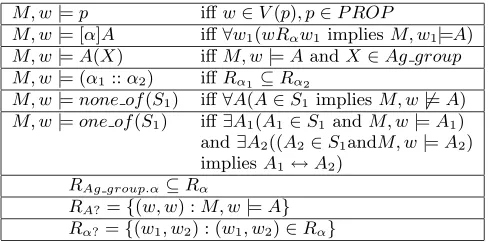
The semantics of ANML can be modelled through accessi-bility relations between possible worlds [12]. As for PDL, worlds are viewed as process states and accessibility rela-tions as processes for state transirela-tions. A formula can ex-press a proposition. It may be interpreted as the set of basic process states (worlds) on which it is true. By introducing syntax for the union of states, ANML enables the state ab-straction of statecharts (section 4.3).
meaning of process α, resulting in a uniquely determined standard model by inductively definingRα for non-atomic processes α. For example, the relation RAg group.α maps worldw1 to worldw2 through an agent or a group execut-ing processα. The functionV represents an assignment of sets of possible worlds to propositions, whereV(p)is the set of worlds where atomic formulap holds, as an interpreta-tion of the atoms in the model. The semantics of the ANML connectors are as follows, wherePROP is the set of propo-sitions:
M, w|=p iffw∈V(p), p∈P ROP
M, w|= [α]A iff∀w1(wRαw1 impliesM, w1|=A)
M, w|=A(X) iffM, w|=AandX∈Ag group
M, w|= (α1::α2) iffRα1⊆Rα2
M, w|=none of(S1) iff∀A(A∈S1impliesM, w6|=A)
M, w|=one of(S1) iff∃A1(A1∈S1 andM, w|=A1) and∃A2((A2∈S1andM, w|=A2) impliesA1↔A2)
RAg group.α⊆Rα
RA?={(w, w) :M, w|=A}
Rα?={(w1, w2) : (w1, w2)∈Rα}
For the formula M, w |= A(X), the meaning of a state parameterised by an agent depends on the rules and syn-chronisation of the protocol it occurs in. The semantics of M, w |= (α1 :: α2) states that all the worlds obtained through execution of process α1 are elements of the set of worlds possible through performing α2. The relation
RAg group.α maps world w1 to w2 through an agent or a
group executing processα. The set of worlds in the image of relationRAg group.αis a subset of the set of worlds in the image ofRα. In the case of a process executed by two groups
gp1 andgp2, wheregp1⊂gp2, if the processαis the same instance, then Rgp1.α =Rgp2.α On the other hand, if the
two groups are performing different instances of processα, then no relation between the two processesgp1.αandgp2.α is derivable before execution. The success of a process is tested inα? by checking whether its consequential end state holds.
ANML inherits the axioms of a normal modal system. The underlying modal logics are decidable. In addition, we have the axiom (A(X)→A) (e.g. offered(X)→offered). The complexity of ANML and its decidability needs further analysis. We assume that groups of agents in an interaction are finite sets and therefore our formalism does not embody quantification.
3.4
A Multi-Lateral Protocol in ANML
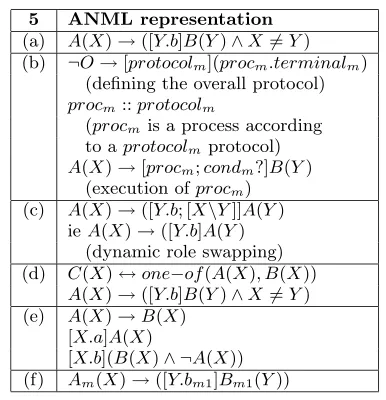
The logical theory in figure 1 shows the application of ANML to represent the multi-lateral protocol in section 2.1. This theory can form the basis for further customisation for ap-plication or domain specific interactions. Here, axiom (1) ensures that a group of agentsG adheres to the following multi-lateral protocol in a process instance called multilat-eral process to vote on a motionm. Double implication in the action-condition rules allows an agent to infer the history of an interaction.
Axioms (2) to (7) define the relations between parent and sub-states. For example, the state of a multi-lateral inter-action is eithermotioned orclosed, but not both (axiom 1). Aclosedstate is eitheragreed,rejectedorwithdrawn(axiom 2). Axioms (5) to (7) ensure that when a parent state is
¬multi interaction↔[G.multilateral processm] closed (1)
multi interaction ↔ one-of ({motioned , closed}) (2) closed↔one-of({agreed , rejected , withdrawn}) (3) motioned↔one-of({pending, seconded, voting}) (4)
¬multi interaction↔none-of({motioned , closed}) (5)
¬closed↔none-of({agreed,rejected,withdrawn}) (6)
¬motioned↔none-of({pending, seconded, voting}) (7)
¬multi interaction↔[ X.motionm] pendingm(X) (8)
pendingm(X)↔([Y.secondm] secondedm(Y)
∨[timeout]withdrawnm
∨[X.withdrawm]withdrawnm)∧¬ (X=Y) (9)
Y∈ G↔( Y.amendm1 :: G.multilateral processm1) (10)
Y∈ G↔( Y.callm2 :: G.multilateral processm2) (11)
secondedm(X)↔([timeout;G.votem]votingm(G)∨
([Y.amendm1;agreedm1?;reinitialise]secondedm1(Y)) ∨
([Y.callm2;agreedm2?;G.votem]votingm(G)))
∧¬(X=Y) (12)
votingm(G)↔[G.countm; (Σyes-votes≥ 12)?] agreedm
[image:4.612.53.298.168.289.2]∨[G.countm; (Σyes-votes< 12)?] rejectedm (13)
Figure 1: Multi-lateral Protocol in ANML
false, none of its sub-states are true. An agent initiates a multilateral process into apendingstate by raising a motion m (Axiom 8), ensuring the interaction cannot be arbitrar-ily re-started. The initiator can withdraw its motion m or the motion may time out into awithdrawnstate (axiom 9). Otherwise from apendingstate, asecondedstate is triggered by another participant seconding the motionm (axiom 9).
Axioms (10) and (11) define the processesamendm1 and
callm2 as complex processes each launching a new
multilat-eral process, involving group G, with motions m1 and m2 respectively. In thesecondedm state, when the countdown
to voting has elapsed, the group votes on the motion m in the state votingm(G) (axiom 12). In the secondedm state,
any agent may also invoke the complexamendm1 transition
to replace the motion m by m1. If the multi-lateral in-teraction spawned by the amendm1 process fails, then the
state of the processmultilateral processmremainssecondedm
without any change. Otherwise if the amendment of mo-tionm succeeds bymultilateral processm1 terminating in an
agreedm1 state, then thesecondedm1(Y)state is entered in
the multilateral processm interaction. The new motion is m1 and the countdown to voting is reinitialised (axiom 12). Similarly theY.callm2 process launches a multi-lateral
inter-action (G.multilateral processm2) with the motionm2being whether to vote immediately on the motionm.
In the votingm(G) state, depending on the number of
“yes” votes, the multilateral interaction terminates success-fully in anagreedmstate, otherwise the motionmisrejected
(axiom 13).
3.5
Analysing the Multi-Lateral Theory
The theory in figure 1 is essentially propositional and may be analysed for completeness using tools such as model-checking or theorem proving. The logical theory of the above protocol in ANML is complete if it is consistent and all states are well-defined (eithertrue orfalse). Here, we do not give the completeness proof for the ANML multi-lateral protocol, since this is not an objective of the paper. A completeness proof for a similar protocol can be found in [12].
sub-states, and in iterative actions, as found when using primi-tive statecharts in section 4.3. ANML also inherits the ax-ioms and properties of PDL for decidability, soundness and completeness. We can thus use an axiomatisation of PDL when analysing and reasoning about protocols in ANML.
ANML is also a program logic, where the properties that a protocol can exhibit are defined as ANML axioms and the sequences of actions inferred from the theory of the protocol are analysed to show whether a property holds [13].
3.6
Extended ANML
The specified form of ANML remains propositional and al-lows the application of logic-based theorems. As presented here, ANML does not support concurrency and process syn-chronisation. This can be achieved by extending ANML with similar operators as in concurrent PDL. We also have not clarified whether the parameters in a state may be in-creased dynamically and must be finite. For example, it is not clear whether a state may or should store more than one set of agents and whether the order of the parameters matter. There remains thus particular applications where ANML may not have enough expressiveness although we have found it to be adequate for most usual protocols. Of course, in case of lack of expressiveness, the notation may be further augmented.
4.
GRAPHICAL METHODOLOGIES
The ANML theory of the multi-lateral protocol in figure 1 defines all the possible states and actions in an interaction and therefore embodies the full details of the multi-lateral protocol. In addition, combined with a parser, ANML can act as a programming language for executing interaction protocols. However, as can be seen, although the theory facilitates automatic verification and validation, its struc-ture may be hard to grasp. To assist comprehension, we propose the translation from a logical theory of a protocol into a diagrammatic notation for more intuitive human un-derstanding.
From our experience in expressing and verifying proto-cols, we provide an analysis of the expressiveness of vari-ous currently-used methodologies for our purpose, including AUML, Petri nets and statecharts. This analysis also stands as a comparison between the different notations and our ap-proach for representing agent interaction protocols.
4.1
Specifying Protocols in AUML
Bauer et al. [2] have proposed AUML, (Agent Unified Mod-eling Language), as an extension of UML to define inter-action protocols between agents. AUML is intended to be a graphical specification technique, which relies partly on FIPA ACL by using a subset of its communicative acts as messages.
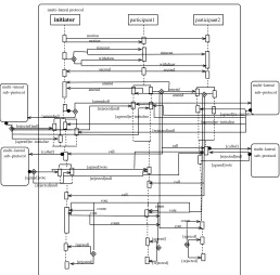
An AUML Interaction Protocol (IP) diagram expresses a protocol in the form of a UML sequence diagram with ex-tensions specific to AUML (as shown in Figure 2). Agents are assigned to roles, belong to classes and an IP diagram shows interactions between these agents along a timeline. An arrow indicates an unnested, asynchronous communica-tion while a diamond means a decision point that can result in zero or more communications being sent (no diamonds – all threads are sent concurrently, an empty diamond – zero or more messages may be sent and a crossed diamond –
exactly one message may be sent).
multi−lateral sub−protocol
multi−lateral sub−protocol
second second
multi−lateral protocol
motion motion
initiator participant1 participant2
timeout
withdraw
timeout
withdraw
multi−lateral sub−protocol
[rejected]null
[agreed]re−initialise
[agreed]re−initialise
[agreed]re−initialise
[rejected]null
[image:5.612.317.575.75.329.2][rejected]null [amended]
[amended]
amend amend
[agreed]re−initialise amend amend
call call
[called]
multi−lateral sub−protocol [called]
[rejected]null call
call
[rejected]null
[agreed]vote
[agreed]vote
[agreed]vote
[rejected]null
vote
vote vote
vote
count
count count
count
[agreed]
[rejected]
[agreed] [agreed]
[rejected] [rejected]
Figure 2: The Multi-Lateral Protocol of Section 2.1 in AUML.
4.1.1
Advantages of AUML
The benefits of using AUML include the following:
• The process of an interaction over time is explicitly expressed through timelines, allowing a visual repre-sentation of events over time.
• The exchange of messages between the different roles are shown explicitly as arrows.
• UML users are already familiar with most of AUML features.
4.1.2
Disadvantages of AUML
Despite both our understanding of the multi-lateral protocol from extensive analysis and past experience with the AUML notation [12], it took four hours to draw up the multi-lateral protocol in AUML using thexfiggraphical tool. In this vein, we notice the following drawbacks of specifying protocols in AUML:
• Cluttered AUML diagrams are easy to misinterpret and a large amount of time and effort is required for developing and understanding reasonable interaction protocols in AUML.
• A major drawback of AUML is the inability to bind roles, cardinalities, access agent identities or interact-ing as in a forum. As many timelines may be needed as the maximum number of identified participants.
• Conditions at some decision points are undefined be-cause an AUML diagram does not show states.
• Redundancy is hard to debug and modify. Actions that are possible by any agent have to be expressed on all the timelines.
• There is no easy way to express time-dependent actions such as timeouts, deadlines or ubiquitous messages like rejections at any time.
• There is no notion of history because states are not identified.
• Termination of the interaction is not obvious, espe-cially when the threads of interaction are abbreviated to a single timeline.
Of course, there are ways to correct some of the deficien-cies, but it remains hard to capture them-nnature of agent interactions in a graphical notation like AUML. For exam-ple, the latest version of AUML, branches are introduced at a timeline to identify an agent, but at the expense of in-creased complexity. OCL [19] has been proposed as a textual representation of UML and could be extended for AUML di-agrams. However OCL is essentially a constraint language and has met several criticisms amongst which its lack of for-mality [18]. See [14] and [12] for a more detailed critique of AUML protocols.
4.2
Specifying Protocols in Petri Nets
Petri nets are another candidate for graphically modeling interaction protocols. In Petri nets, tokens are used to sim-ulate and synchronise dynamic and concurrent activities and algebraic equations can be derived from Petri nets. The dy-namics of a Petri net are a sequence of transition firings where tokens are taken away from input places to output places. Petri nets are used in a variety of applications in-cluding communication networks. However a weakness of Petri nets is the complexity problem; Petri-net-based models tend to become too large for analysis even for a modest-size system [9].
Interaction protocols expressed in Coloured Petri nets can be found in [3], [10] and [17]. The latter expresses in Petri nets some of the protocols proposed in AUML by FIPA [1]. Figure 3 is a coloured Petri net of the multi-lateral interac-tion according to the notainterac-tion used in [10] and [3]. We have not shown the full details of the protocol so as not to render the diagram illegible.
4.2.1
Advantages of Petri Nets
Petri nets exhibit a number of useful features of which some worth mentioning are given below:
• Petri nets allow concurrency and synchronisation in the execution of threads.
• A large array of tools have been developed to detect conflicts and properties such as deadlocks or liveness and evaluate performance.
motioned
motioned motioned
seconded
seconded seconded
voting
voting
voting
agreed
rejected agreed
agreed
rejected rejected start
motion msg(m)
timeout
withdraw
withdrawn
withdrawn
withdrawn timeout
timeout withdraw
withdraw
?
? ?
second msg(m)
msg(m) msg(m)
vote
amend vote call
amend
vote call
msg(m)
msg(m)
msg(m)
msg(m) msg(m)
msg(m1)
msg(m1) msg(m1)
msg(m1)
msg(m)
msg(m) msg(m) msg(m1)
msg(m1)
count
count
count
? ?
?
?
? ?
?
msg(m) call Agent (role) initiator
Agent (role) seconder
call
call
call call
[image:6.612.316.574.53.248.2]Agent (role) amender
Figure 3: The Multi-Lateral Protocol of Section 2.1 in Petri net (notation according to [10]).
• There is a representation of states.
• Petri nets make less cluttered diagrams than AUML.
4.2.2
Disadvantages of Petri Nets
However, we find that there are still limitations to the Petri net notation.
• Interaction protocols in Petri nets are still hard to read as can be seen in figure 3, in [3], [10] and [17] for a contract net protocol, a KQML register performative or a pair-wise negotiation.
• In figure 3, the dotted hexagons and bold “?” indi-cate parts of the Petri net where alternative actions and states cannot be simply expressed in the notation. For example, at the seconded place, an agent either executes anamend,call orvote action, but not all of them as indicated in the Petri net. The logical “∨” and ANML “∪” operators cannot be expressed in standard Petri nets. Thus, the ANML ruleR↔[c∪e]S∨[d]T
cannot be expressed.
• Multiple Petri nets can be used for a protocol. In this case, a Petri net is assigned to each agent role, for example an initiator and a participant agent fol-low different Petri nets [17]. The collection of individ-ual Petri nets associated with all the roles represents the entire interaction protocol, but this leads to issues about how the Petri nets are merged. There are also questions regarding reachability, consistency and mu-tually exclusive access to shared places between two or more Petri nets.
a particular agent doing an action. Here ideally we should have five partitions for five different messages that can be sent by five different agents, yielding the same worst-case scenarios as for AUML.
• In each of the above cases, there is redundancy in re-peating the same parts of a protocol for different agents or roles. This leads to diagrams which are unduly com-plicated and hard to read and suggests poor scalability.
• The notion of agents and execution of an action by an agent is not explicit in the notation.
• It is not easy to replace a piece of protocol by another Petri net [12] and thus Petri nets are not suitable for reusability and abstraction of protocols, including the replacement of sub-protocols.
It may seem that the Petri net in figure 3 is wrong, but this exactly reflects our comments regarding the disadvantages of using Petri net notation for our purpose. More specifically, the lack of an established notation in Petri net to simply ex-press process alternation gives rise to several errors in figure 3. These errors are compounded by the need to replicate the effects of transitions for each sub-net representing an agent or its role. For example, for agent role1, the transitions from the stateseconded, an agent with that role can either amend the motion, call a vote, or the voting process can begin after a countdown, but not more than one of them. We do not know how to represent this alternation in the Petri net and we show a “?” at this point. Our endeavour to nonethe-less represent the multi-lateral protocol while having these open issues may bring about the remark that the protocol is wrong. It is effectively wrong since as shown here vote, call and amend all happen at the same time and triggerboth the statesseconded and voting. But we do not know how to correct this with the current notation. Likewise another error in the Petri net raises the question of how we stop two agents (role1 and role2) from each sending an amend, or for one agent to send a call while the other sends an amend. To represent disjunction, the notation can be augmented with keywords or new constructs.
The multi-lateral protocol does not only involve sending messages between two parties, but also broadcasting a mes-sage to the entire group. This is why we show that a mesmes-sage from an agent (or role) is sent to the rest of the agents in the other partitions. Thus amends and calls may be sent by any one agent to all the other agents. For example, agent role1 sends an amendment to agent role2 and agent role3 and sim-ilarly agent role2 may send amendment to agent role1 and agent role3. The same applies to the call for a vote where agent role1 sends a call to agent role2 and agent role3 or agent role2 may send a call to agent role1 and agent role3. These involve extensive crossing of the arrows representing all the possible messages and give rise to confusion, and make it hard to understand and debug, giving the intuition that figure 3 is incorrect. In fact, we have omitted certain of these broadcast messages so as not to render the Petri net illegible. Thus, our conclusion is that Petri nets (including high-level or coloured) are not ideal for representing agent interaction protocols because of weaknessess in expressive-ness and scalability.
4.2.3
Petri Charts
Petri charts are presented in [7] and are based on Petri net and statechart notations. Petri charts introduce hierarchical net construction in Petri nets with subnets and super-places, allowing net refinements and composition. The approach in [7] focusses on Petri nets, but adding to them the abstrac-tion capabilities of statecharts. However, how a Petri net adds to a statechart is not analysed. Even though Petri charts facilitate a modular approach to the construction of protocols, the above issue about the complexity of Petri nets for representing realistic protocols remain, as can be seen in the Petri charts in [7]. The issues about representing agent roles with partitioning or separate Petri nets still hold in Petri charts. Furthermore, to represent alternative actions at several states would require for each transition in a Petri net to contain a statechart, again increasing the complexity.
4.3
Specifying Protocols in Statecharts
Statecharts [6] are a graphical method to illustrate reactive behaviour and are an extension of conventional finite-state machines and state transition diagrams. This section dis-cusses the desirability of statecharts for illustrating inter-action protocols. To this end, figure 4 is a statechart of the multi-lateral protocol. From our experience with stat-echarts, we mention some general issues about using state-charts for interaction protocols.
agreed
withdrawn withdraw
motion
timeout
closed rejected count
pending seconded call voting vote amend second
motioned
[image:7.612.318.569.342.428.2]multi_interaction
Figure 4: The Multi-Lateral Protocol of Section 2.1 in Statechart (from [11])
4.3.1
Advantages of Statecharts
The statechart notation possesses a number of advantages of interest for expressing protocols. Some of them are listed below:
• Figure 4 is clearer than its AUML and Petri nets coun-terparts.
• When we augment statechart to parameterise actions and states with agents, identifying agents in statechart is relatively simple and does not require new timelines (as in AUML), partitions or new Petri nets. Thus the statechart does not suffer from the drastic rise in com-plexity and redundancy with increase in the number of agents identified, contrary to AUML and Petri nets.
• States and processes are treated equally in statecharts, allowing an agent to refer and reason about the state of an interaction.
4.3.2
Disadvantages of Statecharts
Figure 4 does not show the full multi-lateral protocol be-cause of the lack of expressiveness of the statechart notation in its original form.
• Statecharts do not portray the agents that are involved in exchanging messages and states that become valid do not contain information about which agent trig-gered the state.
• Compound transitions such as amend, call and vote that are themselves new multi-lateral processes are not shown in detail, nor how their results affect the parent interaction shown.
• Incompleteness arises when a parent state can be valid without being in its sub-state [12].
• It must be ensured that entry actions are not possible once the interaction has begun, to prevent arbitrary restarting of the interaction.
Our choice for a graphical notation would be between Petri nets and statecharts. The factors that have influenced our choice of statecharts over Petri nets, with respect to our requirements, include: 1) alternative actions are often part of an interaction and are readily expressible in statecharts but not in standard Petri nets 2) representing agents re-quires less effort in statecharts 3) hierarchies of states in stat-echarts facilitate abstraction, reuse and expressing nested protocols.
It may be remarked that the Petri net notation still has the ability to express concurrent actions and synchronisa-tion between threads for firing a transisynchronisa-tion. In this paper, we specify the core syntax and semantics of ANML and extended statecharts for expressing realistic and sequential agent interactions. Both ANML and statechart can be ex-tended as needs be for more expressiveness. In a more pow-erful ANML embracing the concurrent and synchronisation capabilities of Petri nets, places, transitions and arcs in Petri nets are respectively analogue to states, intermediate states and processes in ANML. The rules in ANML translate how the places and transitions are connected with arcs. Concur-rent ANML reuses the operators from concurConcur-rent PDL [4]. The concurrent execution of processesαandβis expressed as “α∩β”. More details on concurrent ANML can be found in [12].
Therefore we accompany our logical notation of extended PDL with extended statecharts as a graphical notation. Af-ter all, statecharts stem from the same researcher (David Harel) who has contributed extensively to propositional dy-namic logic. Statecharts have been given formal semantics [5], but the standard semantics is not based on PDL. One might think that a statechart is a natural graphical rep-resentation of PDL, but we need ANML-like extensions to capture the state abstraction of statecharts. The contribu-tion here is to extend these two notacontribu-tions for representing agent interaction protocols and fulfil the needs and open issues found in section 4.
5.
EXTENDING STATECHARTS
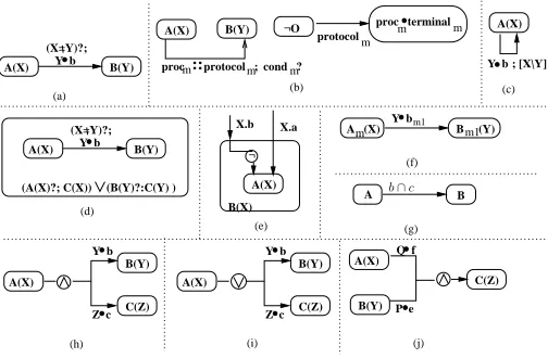
We render the portrayal of protocols in statecharts more complete by providing additional constructs to the state-chart notation. Moreover, we add to statestate-charts, ANML
constructs for dealing with agents performing actions, trig-gering states and with nested protocols. Our extended stat-echart notation thus benefits from the same semantics as ANML because they both share a set of constructs. This al-lows developers to learn only one semantic specification for both the graphical (specification) and the logical (implementation-related) methodologies. To this end, figure 5 presents the additional constructs for extending statecharts. The arcs in the original statechart notation represent alternative ac-tions, i.e. only one of the arcs is executed. Figure 5 shows how we augmented statecharts with ANML-like formulas and processes.
A(X) B(Y) (X=Y)?;
Y b
proc terminalm m
¬O A(X)
Y b ; [X\Y]
(c)
A(X) B(Y) (X=Y)?;
Y b
A(X)
B(Y) Y b
Z c A(X) ¬
B(X) X.a X.b
(e)
Y bm1
A (X)m B (Y)m1 (f)
A(X) B(Y) Y b
A(X)
B(Y)
Z c C(Z)
A(X) B(Y)
(a)
protocolm
(b)
(A(X)?; C(X)) (B(Y)?:C(Y) )
(d)
C(Z)
(g)
A B
C(Z) P e
Q f
(i) (j)
(h)
m:: m m
proc protocol ; cond ?
[image:8.612.318.570.197.362.2]b∩c
Figure 5: Extended Statechart Notation
Contrary to what may be perceived, the notations we add to statecharts are entirely new and derive from neither Petri nets nor Petri charts. These extensions do not occur in any of the notations in section 4. They are graphical and an-notational patches derived from PDL in order to make the statecharts adequate for expressing agent interaction proto-cols.
In more detail, figure 5(a) shows the parameterisation of the statesAandB and the processb, whereX andY are two different agents or groups of agents. The process (Y •
b) changes the state A(X) to B(Y), if the test (X 6= Y)? succeeds.
Figure 5(b) shows the nesting of protocols. The process
procm, leading from stateA(X)toB(Y), is a complex
pro-cess that is constrained by the propro-cessprotocolm. The state B(Y) is triggered if the condition condm holds (which can be brought about by the process procm). The right hand side of the diagram 5(b) abstractly definesprotocolm.
In Figure 5(c), we solve the conflicts when two actions may lead to the same state, but with different agent param-eters. Here the notation [X\Y] is read as the parameterX is replaced by the agentY in stateA, leading to the state A(Y).
Figure 5(d) solves conflicts when a parent state consists of two different sub-states with different parameters. Here, from the condition (A(X)?;C(X))?∨(B(Y)?C(Y)), the par-ent state is C(X) if the sub-state A(X) holds, otherwise C(Y) ifB(Y) holds.
sub-states. Here the arrow with a negation explicitly expresses that the processX.bleads to the parent stateB(X), but not to the sub-stateA(X).
Figure 5(f) shows the subscripting of states (AandB) and processbwith an identifierm orm1. This notation is useful in dealing with instances of a process that can occur several times in a single interaction as a result of nested processes.
Z.call
m2::G.multi_process ;agreed ?;G.votem2 m2
G.count ;
m
G.count ;m
multi_interaction
m1
G.vote
closed
(#yes<1/2)?
X.motionm m
m
G.multi_process ;
agreed
rejected m
seconded (Y) voting (G)
m
(X=Y)?; Y.second
m
(#yes> 1/2)?
m m1
m m
pending (X)
m
m
Z.amend
withdrawn
::
¬multi_interactionm G.multi_processm multi_interaction agreedm
timeout
X.withdraw
reinitialise;[Y\Z]
motioned
agreedm1?; ∩[m\m1]
Figure 6: The Multi-Lateral Protocol of Section 2.1 in Extended Statechart.
We can now represent all the details of the multi-lateral protocol in our extended statechart notation, as shown in figure 6. Even though figure 6 is complete, while figures 2 and 3 are incomplete, it can be seen that the extended statechart is by far less cluttered and more readable, thus justifying our choice for extending statecharts.
6.
A COMBINED APPROACH
Our combined approach consists of the extended forms of PDL and statecharts presented in the previous sections. In-teraction protocols between agents can be specified and im-plemented using these methodologies, where a major advan-tage is the sharing of a set of constructs and their seman-tics for executing processes and triggering interaction states. This stands as a bridge between theory and application or specification and implementation of protocols. In this sec-tion, we discuss the combined approach.
6.1
Meeting the Requirements
We analyse whether the combined approach meets the re-quirements for a language for agent interaction protocols discussed in section 2.2. The aim stated in the premises of the paper is to propose an approach that specifies verifiable interaction protocols clearly and completely, and yet is close to an executable form. The extended statecharts notation fulfils the first requirement for a diagrammatic notation. In addition, figure 6 is an example of the conciseness of the extended statecharts notation over AUML and Petri nets.
ANML is a formal language with specified syntax and se-mantics and verification and model checking may be applied on ANML protocols (requirement 2). Furthermore, imple-mentation tools such as a parser and interpreter or modal prolog systems could allow the execution of protocols in ANML (requirement 3). ANML is essentially propositional and useful logic-based theorems are applicable (requirement 4). Properties of a protocol can be specified as axioms in
ANML and ANML protocols can be validated against these properties [13] (requirement 5).
Both extended statecharts and ANML essentially adopt a state automata representation and express processes and states of an interaction (requirement 6). Furthermore, in both notations, we parameterise the processes and states with the agents or groups of agents performing and trig-gering them respectively. Generic actions may be typed with roles or the roles may be bound to identified agents without significant increase in complexity. The combined approach is thus suitable in a multi-agent domain (require-ment 7). Nested interactions are represented by the :: oper-ator in both ANML and extended statecharts (requirement 7). Hierarchies of states allow abstraction and reuse of pro-tocols(requirement 8).
6.2
Translating between Methods
Using a unified modeling/implementation language reduces the amount of effort on the part of designers and program-mers. ANML and extended statecharts are linked through the ANML constructs used inside the statecharts. We can translate statecharts to ANML (corresponding to a transla-tion from specificatransla-tion to an implementatransla-tion-like language for execution, automated verification and validation) and from ANML to statecharts (for visual understanding). Fig-ure 6 and the theory in figFig-ure 1 are complementary; the for-mer represents the multi-lateral protocol in extended state-charts and the latter in ANML.
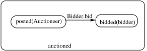
auctioned
[image:9.612.58.289.138.289.2]posted(Auctioneer) Bidder.bid bidded(bidder)
Figure 7: Extended Statechart of a Simple Auction-ing Protocol
In essence, a protocol in extended statecharts is a graph-ical visualisation of the set of rules in an ANML theory, itself an extension of PDL for agents. ANML rules between states (parent and sub-states) correspond to the hierarchy of states in statecharts. ANML action-condition rules are translated into state transitions. For example, in figure 7, the relation between the parent states is translated in the ANML ruleauctioned(X)↔one−of({posted, bidden}) and the state transition is expressed as posted(Auctioneer) ↔
[Bidder.bid]bidded(Bidder) in ANML. Similarly a reverse
translation from the ANML theory yields the correspond-ing statecharts. Thus, we find the translation is relatively straightforward between the two methodologies.
6.3
Modular Translation between Methods
We first provide a general translation from each extended statechart in figure 5 to ANML. A translation from ANML to extended statecharts is similarly performed from the rules in this section to figure 5. The general PDL ruleA→[b]B
[image:9.612.364.510.363.414.2]Table 1: From Extended Statecharts to ANML
5 ANML representation
(a) A(X)→([Y.b]B(Y)∧X6=Y)
(b) ¬O→[protocolm](procm.terminalm)
(defining the overall protocol)
procm::protocolm
(procm is a process according
to aprotocolmprotocol)
A(X)→[procm;condm?]B(Y) (execution ofprocm) (c) A(X)→([Y.b; [X\Y]]A(Y)
ieA(X)→([Y.b]A(Y) (dynamic role swapping) (d) C(X)↔one−of(A(X), B(X))
A(X)→([Y.b]B(Y)∧X6=Y) (e) A(X)→B(X)
[X.a]A(X)
[X.b](B(X)∧ ¬A(X)) (f) Am(X)→([Y.bm1]Bm1(Y))
7.
CONCLUSIONS
This paper has addressed the need for formalised and more expressive logical and graphical methodologies for precisely specifying and validating protocols and their properties for interaction between rational agents. Towards this end, we propose a combined approach consisting of extended PDL and extended statecharts. We specify a formal language, called ANML, based on PDL for representing and reasoning about agent interaction protocols. ANML can be developed into a language for programming libraries of protocols and logic-based theorems can be applied to ANML theories. The notations can also be applied to protocols other than multi-agent interactions, but our extensions allow us to consider the domain of agent executing actions.
We show the application of our language using an exam-ple multi-lateral protocol. Case studies of AUML, Petri nets and statecharts convince us that of all methods, statecharts are the closest to a completely expressive graphical nota-tion. It seems that we can now enhance statecharts to match the ANML formalism. Future work includes analysing the complexity and soundness of ANML and a comparison with other logics such as action logics, event calculus and the mu-calculus.
8.
REFERENCES
[1] Foundation for intelligent physical agents, fipa. agent communication language. Inhttp://www.fipa.org. [2] B. Bauer, J. P. Muller, and J. Odell. Agent UML: A
Formalism for Specifying Multiagent Software Systems. In AOSE, pages 91–104, 2000.
[3] R. Cost, Y. Chen, T. Finin, Y. Labrou, and Y. Peng. Modeling agent conversations with colored petri nets. In Workshop on Specifying and Implementing Conversation Policies, pages 59–66, 1999.
[4] R. Goldblatt.Logics of Time and Computation. CSLI, 1987.
[5] D. Harel and A. Naamad. The STATEMATE semantics of statecharts.ACM Transactions on Software Engineering and Methodology, 5(4):293–333, 1996.
[6] D. Harel and M. Politi.Modeling reactive systems with statecharts. McGraw-Hill, 1998.
[7] T. Holvoet and P. Verbaeten. Petri charts: an alternative
technique for hierarchical net construction. InProceedings of IEEE Conference on System, Man, and Cybernetics, October, 1995.
[8] R. Milner.Communication and Concurrency. Prentice Hall, 1989.
[9] T. Murata. Petri nets: Properties, analysis, and applications.IEEE, 77(4):541–580, 1989.
[10] M. Nowostawski, M. Purvis, and S. Cranefield. A layered approach for modelling agent conversations. In2nd Work. on Infrastructure for Agents, MAS, and Scalable MAS, Agents 2001.
[11] OMG.Negotiation Facility Specification. The Object Management Group, Inc., http://www.omg.org, 2002. [12] S. Paurobally.Rational Agents and the Processes and
States of Negotiation. Imperial College, Ph.D. Thesis, 2002. [13] S. Paurobally and J. Cunningham. Safety and liveness of
negotiation protocols. InAISB2002 Intelligent Agents in virtual market track., 2002.
[14] S. Paurobally and R. Cunningham. Verification of protocols for negotiation between agents. InECAI-15, pages 43–48, 2002.
[15] S. Paurobally, R. Cunningham, and N. R. Jennings. Ensuring consistency in joint beliefs of interacting agents. In2nd Int. Joint Conf. on Autonomous Agents and Multi-Agent Systems, 2003.
[16] V. R. Pratt. Semantical considerations on Floyd-Hoare logic. InProceedings of 17th IEEE Symposium, Foundations of Computer Science, pages 109–121, 1976. [17] M. K. Purvis, S. Cranefield, M. Nowostawski, R. Ward,
D. Carter, and M. A. Oliveira. Agentcities interaction using the opal platform. InWork. on Challenges in Open Agent Systems, AAMAS, 2002.
[18] M. Richters and M. Gogolla. On formalizing the UML object constraint language OCL. InProc. 17th
International Conference on Conceptual Modeling (ER), volume 1507, pages 449–464. Springer-Verlag, 1998. [19] J. Warmer and A. Kleppe. Ocl: The constraint language of
![Figure 3: The Multi-Lateral Protocol of Section 2.1in Petri net (notation according to [10]).](https://thumb-us.123doks.com/thumbv2/123dok_us/1014380.616326/6.612.316.574.53.248/figure-multi-lateral-protocol-section-petri-notation-according.webp)
![Figure 4: The Multi-Lateral Protocol of Section 2.1in Statechart (from [11])](https://thumb-us.123doks.com/thumbv2/123dok_us/1014380.616326/7.612.318.569.342.428/figure-multi-lateral-protocol-section-in-statechart.webp)