Iterative Channel Estimation
Bee Leong Yeap, Choong Hin Wong, and Lajos Hanzo, Senior Member, IEEE
Abstract—A reduced complexity trellis-based turbo equalizer
known as the in-phase (I)/quadrature-phase (Q) turbo equalizer (TEQ-IQ) invoking iterative channel impulse response (CIR) esti-mation is proposed. The underlying principle of TEQ-IQ is based on equalizing the I and Q component of the transmitted signal independently. This requires the equalization of a reduced set of separate I and Q signal components in comparison to all of the possible I/Q phasor combinations considered by the conventional trellis-based equalizer. It was observed that the TEQ-IQ operating in conjunction with iterative CIR estimation was capable of achieving the same performance as the full-complexity conven-tional turbo equalizer (TEQ-CT) benefiting from perfect CIR information for both 4- and 16-quadrature amplitude modulation (QAM) transmissions, while attaining a complexity reduction factor of 1.1 and 12.2, respectively. For 64-QAM, the TEQ-CT receiver was too complex to be investigated by simulation. How-ever, by assuming that only two turbo equalization iterations were required, which is the lowest possible number of iterations, the complexity of the TEQ-IQ was estimated to be a factor of 51.5 lower than that of the TEQ-CT. Furthermore, at BER= 10 3the performance of the TEQ-IQ 64-QAM receiver using iterative CIR estimation was only 1.5 dB away from the associated decoding performance curve of the nondispersive Gaussian channel.
Index Terms—Convolutional codes, decoding, in-phase (I),
iterative equalization, quadrature-phase (Q), reduced complexity, turbo equalization.
I. INTRODUCTION
I
N A communications system, the received signal is de-graded by intersymbol interference (ISI) introduced by the channel. The effects of ISI can be mitigated by employing equalization [1], [2] and the associated bit-error rate (BER) can be further reduced by using error control coding [3] schemes. However, when performing the equalization and channel decoding independently, we cannot completely compensate for the performance loss due to the ISI, even when soft de-cisions are passed from the equalizer to the channel decoder [3]. Instead, by performing the equalization and decoding iteratively, as in the turbo equalization scheme proposed byManuscript received February 11, 2000; revised June 22, 2001; accepted June 22, 2001. The editor coordinating the review of this paper and approving it for publication is K. Wilson. This work was supported in part by the IST Project IST-1999-12070 TRUST, which is partly funded by the European Union.
C. H. Wong was with the Department of Electronics and Computer Science, Univerity of Southampton, Southampton, SO17 1BJ, U.K. He is now with Mul-tiple Access Communications Ltd., Southampton, SO16 7NS U.K.
B. L. Yeap and L. Hanzo are with the Department of Electronics and Computer Science, Univerity of Southampton, Southampton, SO17 1BJ, U.K. (e-mail: [email protected]; http://www-mobile.ecs.soton.ac.uk).
Digital Object Identifier 10.1109/TWC.2002.806355
Douillard et al. [4], the residual ISI can be mitigated effectively. Gertsman and Lodge [5] then showed that the iterative process of turbo equalization can be exploited to compensate for the performance degradations due to imperfect channel estima-tion. In order to achieve better BER performance, combined turbo coding and turbo equalization schemes have also been investigated by Raphaeli and Zarai [6]. Knickenberg et al. [3], [7] subsequently proposed a noniterative joint equalization and decoding technique based on a supertrellis structure. This technique yielded an optimum performance, but was restricted to incorporating simple interleavers due to the high complexity incurred by large interleavers.
Due to complexity reasons, early turbo equalization investi-gations using the conventional trellis-based equalizer (CT-EQ) were constrained to applying binary phase-shift keying (BPSK) and quadrature phase-shift keying (QPSK) modulation schemes [5] and to limited channel impulse response (CIR) durations. This is because the computational complexity incurred by the CT-EQ is dependent on both the maximum CIR duration and on the modulation mode utilized. Hence, turbo equalization research has been focused on developing reduced complexity equalizers, such as the low-complexity linear equalizer pro-posed by Glavieux et al. [8] and the radial basis function (RBF) equalizer by Yee et al. [9].
Motivated by these trends, we propose a reduced complexity trellis-based turbo equalizer, referred to as the in-phase/quadra-ture-phase turbo equalizer (TEQ-IQ), invoking iterative channel estimation [10] for M-level quadrature amplitude modulation (M-QAM) [1] systems. The performance of the TEQ-IQ scheme is compared with that of the conventional trellis-based turbo equalizer (TEQ-CT) benefiting from perfect CIR information.
The outline of this contribution is as follows. Section II provides an overview of the system model, while Sections III and IV describe the principles and the operations of the reduced complexity equalizer in the context of turbo equalization. Subsequently, Sections V and VI discuss the complexity of the TEQ-IQ and summarizes the simulation parameters. This is followed by the system performance in Section VII. Finally, Section VIII provides our concluding remarks.
II. SYSTEMMODEL
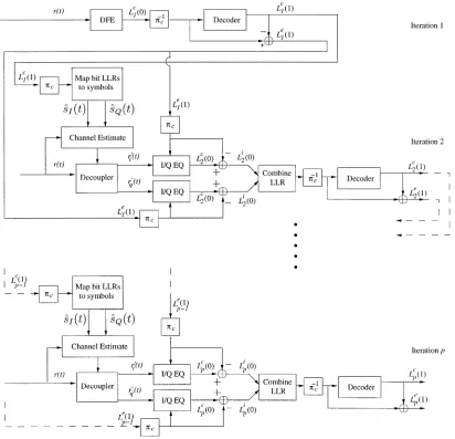
In our investigations, we have considered a coded M-QAM system employing turbo equalization at the receiver, as il-lustrated in Fig. 1. At the transmitter, the source bits are
Fig. 1. A coded M-QAM system employing a turbo equalizer at the receiver.
convolutionally encoded to yield the coded bits . Subse-quently, the coded bits are channel interleaved and passed to the modulator, which produces the modulated signal . The signal is transmitted over the channel characterized by the CIR and further corrupted by the zero-mean complex white Gaussian noise , having a double-sided power spec-tral density of , at the receiver to yield the received signal . Since the CIR is complex and, therefore, consists of the I component and Q component , the resultant received signal is
(1) and and are the I and Q components of the trans-mitted signal . Also note that and are the quadrature components of the Gaussian noise .
At the receiver, the CIR is estimated using an iterative CIR es-timation technique [10], [11]. Specifically, during the first turbo equalization iteration the CIR is estimated using the least mean square (LMS) algorithm [12] and the training sequence men-tioned previously. The initial step-size of the LMS algorithm is set to 0.05. Subsequently, the CIR estimate acquired during the first iteration is then utilized by the soft-in/soft-out (SISO) [13] equalizer, which generates soft decisions in the form of the logarithmic probability ratios known as log-likelihood ratios (LLR). These soft decisions are passed to the channel decoder, which computes the reliability information referred to as a
pos-teriori information, corresponding to the coded bits. During the
next iteration, instead of using the training sequence for re-es-timating the CIR, the soft estimates of the entire transmission burst’s symbols derived from the a posteriori information of the SISO decoder are employed. Here, a smaller step-size of 0.01 is utilized in the LMS algorithm. The decoder’s a posteriori in-formation is converted from the ratio of probability values into soft estimates of the modulated symbols by computing the sta-tistical average of the transmitted symbol probabilities [8]. Fur-ther details of this conversion are provided in Section IV-A. This CIR estimation process is repeated for each turbo equalization iteration.
Although there exists a wide range of low complexity SISO algorithms, we have opted for using the logarithmic-maximum
a posteriori (Log-MAP) algorithm [14], [15] for both the
SISO channel equalizer and for the channel decoder, since the Log-MAP algorithm achieves optimal performance, despite having a reduced computational complexity compared with the original maximum a posteriori (MAP) algorithm [16].
III. PRINCIPLES OFI/Q-PHASEEQUALIZATION
As shown in (1), the I/Q components of the received signals, namely and , become dependent on and after transmission over the complex CIR. We refer to the cross correlation between and in and as cross
coupling. This cross coupling of the transmitted signal
compo-nents requires the receiver to consider a high number of signal combinations, hence necessitating the use of many equalizer trellis states. We can reduce the number of states significantly, when the cross coupling is removed such that the quadrature components of the decoupled channel output and are solely dependent on or , respectively. The decou-pling operation is performed by removing the undesired quadra-ture component from the received signal using the symbol and channel estimates generated by the receiver. If these estimates were perfect, perfect decoupling could be achieved. In reality, no perfect symbol and channel estimates are available. How-ever, the initial rough estimates improve considerably during the consecutive turbo equalization iterations, ultimately yielding a performance close to that of the system using no I/Q decoupling. This process will be elaborated on in Section IV-B. For trans-mission over real-valued channels, no decoupling is necessary. This is because and from (1) it is observed that and are solely dependent on the and , respec-tively. The decoupling operation is only essential for transmis-sions over channels described by complex-valued CIRs.
Fig. 2. Schematic of the turbo equalizer employing a decision feedback equalizer (DFE) and a SISO channel decoder in the first-turbo equalization iteration. In subsequent iterations, two reduced complexity SISO in-phase/quadrature-phase equalizers (I/Q-EQ) and one SISO channel decoder is employed. The notation represents a channel interleaver, while is used to denote a channel deinterleaver.
the number of bits used to represent a symbol is . Therefore, the I/Q-EQ associated with will compute the
a posteriori LLRs of the first number of bits, while the other I/Q-EQ determines the LLRs of the following bits. Subsequently, the LLRs of both I/Q-EQs are multiplexed in the schematic of Fig. 2 before being passed to the decoder, in order to ensure that they are rearranged in the right order, i.e., in the
order of .
Note that it is important to identify the bits, which are mapped to the I and Q component of the signal. For example, as in the previous 16-QAM example, bits and correspond to signal , while and map to . This is because the channel decoder operates on the received information on a coded bit basis. Therefore, the I/Q-EQ of each quadrature arm must de-termine the LLR values corresponding to the coded bits. If the LLRs of the quadrature symbols are determined instead, then an additional processing step is required for converting the LLR values of the quadrature symbols to the LLRs of the coded bits. Therefore, the above-mentioned principle of the I/Q-EQ is not directly applicable to M-ary phase shift keying (M-PSK), which
has values higher than four, such as , 16, 32, since the bits of the multilevel symbol do not distinctly map to and
as in the above square-shaped M-QAM constellations. IV. OVERVIEW OF THEREDUCED COMPLEXITY
TURBOEQUALIZER
are denoted as stage 0, while the channel decoder as stage 1. Fur-thermore, in our discussions related to multilevel QAM, the term
bit refers to either the 1 or 1 bit of the M-QAM symbols. For 4-QAM, there are two bits in a symbol, whereas a 16-QAM symbol consists of four bits.
At the first iteration, the decision feedback equalizer (DFE) is invoked, since it is a low-complexity approach to providing ini-tial estimates of the transmitted symbols, as compared with the more complex CT-EQ. Subsequently, the SISO channel decoder of Fig. 2 generates the a posteriori LLR , from which the extrinsic information of the encoded bits, namely is extracted. In the next iteration, the a posteriori LLR is used to regenerate estimates of the I and Q components of the transmitted signal, namely and , as seen in the “MAP bit LLRs to symbols” block of Fig. 2. The a posteriori information was transformed from the logarithmic domain to modulated symbols using the approach employed in [8]. The estimates of the transmitted quadrature components and are then convolved with the estimate of the CIR . At the decoupler block of Fig. 2, the resultant signal is used to remove the cross-coupling effect—seen in (1)—from both quadrature components of the transmitted signal, yielding and . As mentioned previously, the cross coupling between
and in each quadrature arm of the received signal is removed, in order to reduce the number of possible signal combinations, hence reducing the number of equalizer states in the trellis. After the decoupling operation, and are passed to the I/Q-EQ in the schematic of Fig. 2. In addition to these received quadrature signals, the I/Q-EQ also processes the
a priori information received, which is constituted by the
ex-trinsic LLRs from the previous iteration and generates the a posteriori information . Subsequently, the combined channel and extrinsic information is extracted from both I/Q-EQs in Fig. 2 and combined, before being passed to the Log-MAP channel decoder. As in the first turbo equalization it-eration, the a posteriori and extrinsic information of the encoded bits, namely and , respectively, are evaluated. The following turbo equalization iterations also obey the same se-quence of operations, until the iteration termination criterion is met.
A. Conversion of the Decoder A Posteriori LLRs Into Symbols
Let us now highlight the operation of the top left block of Fig. 2 at iteration 2. Here, the statistical average of the I and Q signals, denoted as and , respectively, can be ob-tained by using [8]
(2)
[image:4.612.304.553.63.125.2]where denotes the expectation or averaging operation, is the number of constellation points in each quadrature arm of a particular modulation mode and is the equalizer symbol estimate. The terms and
Fig. 3. The Gray mapping [18] of the 16-QAM mode depicting the in-phase and quadrature-phase components and the corresponding bit assignments.
represent the th I and Q signal, as illustrated in Fig. 3 for 16-QAM.
As an example, consider the 16-QAM symbol, which con-sists of four bits, namely , and . Assume that the first two bits ( ) correspond to a coordinate on the I axis of the signal constellation, while the other two bits ( ) rep-resent a point on the Q axis , as depicted in Fig. 3. With reference to Fig. 3, which illustrates the Gray mapping used in each quadrature arm of the 16-QAM signal constellation and by employing (2), the regenerated quadrature components of , namely and can be expressed as
(3) and
(4) where the probabilities and for can be written as and , respectively, since the symbol corresponds to bits and , while the symbol is represented by bits and . Note also that can be expressed as
, since the transmission of bits and can be assumed to be statistically independent events, when channel interleaving is employed. Similarly, the probability can be written as . Therefore, it is possible to infer the associated 16-QAM symbols, once the probabilities of the bits in the symbol are known. This can be extracted from the decoder’s a
posteriori LLR in Fig. 2, since the LLR is the ratio of the probability that the transmitted coded bit, was a logical “ 1” to the probability that .
B. I/Q Decoupling Operation
tion, which reflects our confidence in whether a 1 or 1 coded bit was transmitted. The conversion process from the decoder LLRs to M-QAM symbol estimates was described in the pre-vious section. Subsequently, these symbols are convolved with the I and Q CIR estimates, in order to generate and . These estimated signals are then removed from the received signal , in order to generate
(5)
where and are the error functions
(6) which arise when inaccurate CIR estimates and low-confidence M-QAM symbol estimates are generated. Similarly, is ob-tained by subtracting and from , which are generated by using the symbol estimates and the I and Q CIR estimates.
In the first turbo equalization iteration, the values of the error functions are high due to the poor reliability of the regenerated signal estimates. However, through successive turbo equaliza-tion iteraequaliza-tions the performance of the TEQ-IQ improves, since the reliability of the symbol estimates and CIR estimates is en-hanced. The improved reliability of the regenerated symbol es-timates reduces the decoupling errors, hence improving the per-formance of the TEQ-IQ. This will be demonstrated using our simulation results in Section VII.
V. COMPLEXITY OF THEITEQ-IQ
In order to simplify the complexity analysis of the turbo equalizers, the complexity of the channel encoder, modulator, interleaver, and deinterleaver has been assumed to be neg-ligible. Therefore, the complexity of the turbo equalizer is dependent only on the complexity of the equalizer, the decoder and the number of turbo equalization iterations performed. Since, the complexity of the equalizer and decoder is added and subsequently multiplied by the number of turbo equalization iterations, we must adopt the same measure of complexity for both the equalizer and decoder, which in this paper is the number of associated trellis transitions per information bit. Therefore, the complexity of the equalizer, which is dependent on the number of trellis transitions per coded bit, must be normalized by the overall throughput , which is the product of the number of bits per symbol (BPS) and the code rate , to become the number of transitions per information bit.
CT-EQ
(7) whereas for the single I/Q-EQ trellis stage
-EQ Number of states Number of transitions
(8) For the rate and constraint length convolutional decoder, the complexity incurred is
Number of states Number of transitions (9) since the convolutional code is a binary code, which has two branches leaving each state.
Having determined the complexity of the equalizer and de-coder as a function of the number of transitions per information bit, the complexity of the TEQ-CT can be estimated as
TEQ-CT Itr TEQ-CT (10)
while the complexity of TEQ-IQ is
TEQ-IQ
Itr TEQ-IQ (11) where Itr denotes the number of iterations performed by the re-ceiver. A factor of two was introduced in the term 2
the TEQ-IQ in the first iteration is only dependent on the com-plexity of the convolutional decoder.
For comparison, we have also evaluated the performance of a low-complexity system, where the decision feedback equalization and turbo convolutional (TC) decoding are per-formed independently. We refer to this system as DFE-TC. The associated complexity DFE-TC is given by
DFE-TC Itr TC (12) where the complexity of the turbo decoder is expressed as 2 2 Itr TC , since the turbo decoder consists of two convo-lutional decoders. As in (11), we have assumed that the DFEs complexity is negligible.
VI. SYSTEMPARAMETERS
In our forthcoming deliberations, the performance of our pro-posed TEQ-IQ receiver employing a convolutional decoder is investigated in the context of square-constellation M-QAM sys-tems having a fixed system delay. We will elaborate on our con-siderations related to the system delay after describing the trans-mission burst structure.
The rate , constraint length , recursive sys-tematic convolutional (RSC) code having octal feedback and feedforward generator polynomials of and , respectively, was invoked in the turbo-equalized M-QAM sys-tems considered. For the DFE-TC system, we have used the rate , convolutional constituent codes employing the feedback generator polynomial of and feed-forward polynomial of . A constraint length of was employed for the convolutional turbo codes for the sake of a fair comparison with the similar-complexity convolu-tional codes. In our investigations, the decoder was set to per-form eight turbo decoding iterations, since experimental inves-tigations have shown that no significant BER performance im-provement is attained by using a higher number of iterations. In the first turbo equalization iteration, the DFE of Fig. 2 was employed, as mentioned in Section IV. The number of forward taps and backward taps in the DFE was 15 and 4, respec-tively. In the subsequent iterations two SISO I/Q-EQs were em-ployed, which utilized the Log-MAP algorithm [14]. The con-volutional decoder used in these turbo-equalized M-QAM sys-tems also employed the Log-MAP algorithm, rather than the less complex and more conventional Viterbi MLSE decoder, in order to supply the turbo equalizer with bit confidence values.
The transmission burst structure used in this system is the FMA1 nonspread burst as specified in the Pan-European FRAMES proposal [17]. It consists of a 27-symbol training sequence, surrounded by two 72-symbol data sequences. At each end of the transmission burst, there are threetail symbols. A transmission frequency of 1900 MHz, signalling rate of 2600 kBd and a vehicular speed of 30 mi/h was used. In order to decide on the tolerable system delay and, hence, the size of the channel interleaver, we considered the maximum affordable delay of a speech system. This system delay is mainly deter-mined by the latency introduced by the channel interleavers, where an entire segment of bits must be received in the interleaver’s buffer, before their transmission can commence.
Here the processing delay attributed to the channel encoding, modulation and turbo equalization operations has been ignored, although practical systems have a processing delay, which allows them to complete their operations “just” before they have to commence processing the next incoming information block. Typically, speech systems can tolerate system delays, which are less than 40 ms. Here, the acceptable delay is conser-vatively set to 30 ms. For example, consider a time-division multiple-access/time-division duplex (TDMA/TDD) system, which employs eight uplink and eight downlink slots and where one transmission slot will be available after every sixteen TDMA slots. Furthermore, since each 72- s burst consists of 144 data symbols, the total number of symbols transmitted within 30 ms corresponds to 3456 symbols. Upon assuming an identical signalling rate, the corresponding number of trans-mitted encoded bits for 4-, 16-, and 64-QAM is 6912, 13 824, and 20736, respectively. Hence, bit-based random channel interleavers of these sizes were invoked in our investigations.
A three-path, symbol-spaced fading CIR of equal weights, described as
(13) was utilized, where is a complex variable possessing Rayleigh fading statistics, which obeys a normalized Doppler frequency of 3.3 10 . Furthermore, the fading magnitude and phase was kept constant for the duration of a transmission burst, a condition which we refer to as employing burst-in-variant fading.
VII. SYSTEMPERFORMANCE
A. 4-QAM System
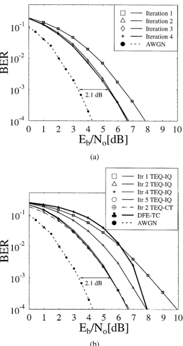
Fig. 4(a) and 4(b) characterizes the performance of the TEQ-IQ using iterative CIR estimation and the TEQ-CT having perfect CIR information for a 4-QAM system, respectively, after four turbo equalization iterations. For comparison, the performance of the noniterative DFE-TC receiver was also plotted in Fig. 4(b). For a transmission delay of 30 ms, the size of the channel interleaver implemented was 6912 bits.
(a)
[image:7.612.74.258.60.408.2](b)
Fig. 4. Performance of the TEQ-IQ technique invoking iterative CIR estimation and the TEQ-CT scheme having perfect CIR information for a convolutional-coded 4-QAM system, possessing a channel interleaver size of 6912 bits communicating over the equally-weighted, three-path Rayleigh fading CIR of (13) using a normalized Doppler frequency of 3.32 10 . (a) TEQ-CT scheme possessing perfect CIR information. (b) TEQ-IQ scheme using iterative CIR estimation.
having perfect CIR information. It was also observed that the TEQ-IQ achieved an gain of 2.0 dB over the DFE-TC, which incurs a complexity of transitions per information bit.
The ability of the TEQ-IQ receiver to mitigate the channel’s ISI was studied as a function of the loss evaluated for the turbo equalization scheme after the critical number of iter-ations with respect to the decoding performance obtained over the nondispersive AWGN channel, i.e., over the ISI-free channel at BER 10 . In this respect, a loss of 2.1 dB was observed, as evidenced by Fig. 4(b).
B. 16-QAM System
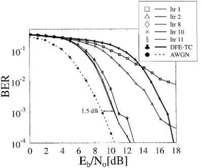
As a further set of results, Fig. 5(a) displays the performance of the TEQ-CT receiver possessing perfect CIR information for 16-QAM transmitted over the equally-weighted three-path Rayleigh fading CIR of (13). A channel interleaving size of 13 824 bits was used, in order to maintain a total system delay of approximately 30 ms. The critical number of iterations was three, when employing the 16-QAM TEQ-CT receiver, whereas for the TEQ-IQ, the critical number of iterations was six, as shown in Fig. 5(b). Comparing the performance
(a)
(b)
Fig. 5. Performance of the TEQ-IQ technique invoking iterative CIR estimation and the TEQ-CT scheme having perfect CIR information for a convolutional-coded 16-QAM system, possessing a channel interleaver size of 13 824 bits communicating over the equally-weighted three-path Rayleigh fading CIR of (13) using a normalized Doppler frequency of 3.32 10 . (a) TEQ-CT scheme possessing perfect CIR information. (b) TEQ-IQ scheme using iterative CIR estimation.
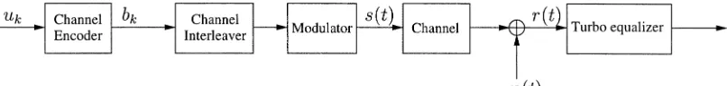
[image:7.612.336.521.61.436.2]Fig. 6. Performance of the TEQ-IQ scheme invoking iterative CIR estimation for a convolutional-coded64-QAM system, possessing a channel interleaver size of 20 736 bits communicating over the equally-weighted three-path Rayleigh fading CIR of (13) using a normalized Doppler frequency of 3.32 10 .
interleaving sizes reduced the correlation between the bits, hence yielding a better performance.
C. 64-QAM System
Examining the performance of our 64-QAM system over the same dispersive Rayleigh fading CIR in Fig. 6, it was observed that the critical number of iterations was ten. The size of the channel interleaver was 20 736 bits. After ten turbo equalization iterations the performance of the TEQ-IQ receiver using itera-tive CIR estimation at BER 10 was only 1.5 dB from the decoding performance curve over the nondispersive Gaussian CIR, as shown in Fig. 6. This was an improvement, when com-pared with the loss of 2.1 and 2 dB suffered by the 4-and 16-QAM systems, respectively 4-and can be attributed to the higher interleaving sizes employed. When compared with the DFE-TC receiver, which incurs a complexity of
at BER 10 , the TEQ-IQ achieved an gain of 6.5 dB. Simulations could not be conducted for the 64-QAM TEQ-CT system, since the trellis-based equalizer required
states and 64 transitions per state, hence, it was too complex to be implemented. However, by assuming that the critical number of iterations for the TEQ-CT was two —which is the minimum number of iterations that has to be performed in order to achieve any iteration gain at all—and noting that ten iterations were per-formed by the TEQ-IQ, it was observed that the complexity of the TEQ-IQ was a factor of 51.5 lower than that of the TEQ-CT.
VIII. CONCLUSION
It was observed that the reduced complexity turbo equalizer receiver, namely the TEQ-IQ scheme, employing two I/Q-EQs and iterative CIR estimation was capable of achieving the same performance as the conventional convolutional coding assisted TEQ-CT scheme having perfect CIR information for 4-QAM and 16-QAM, while maintaining a complexity reduction factor of 1.1 and 12.2, respectively. For 64-QAM, we were unable to evaluate the performance of the TEQ-CT receiver for 64-QAM transmissions over the same dispersive Rayleigh fading CIR due
to the excessive number of trellis states required. In order to compare the complexity of the TEQ-CT and TEQ-IQ, we as-sumed that the critical number of iterations for the TEQ-CT scheme was two. It was observed that the complexity of the TEQ-IQ was a factor of 51.5 lower, than that of the TEQ-CT. Furthermore, at BER 10 the performance of the TEQ-IQ receiver using iterative CIR estimation in Fig. 6 was only 1.5 dB from the decoding performance curve recorded for transmis-sion over the nondispersive Gaussian channel. When the per-formance of the TEQ-IQ was compared with the noniterative and low-complexity DFE-TC receiver, gains of 2.0, 3.5, and 6.5 dB were achieved by the TEQ-IQ for the 4-, 16-, and 64-QAM systems, respectively.
ACKNOWLEDGMENT
The authors would like to thank the contributions of their colleagues and for the enlightening discussions conducted under the auspices of the Trust Project. The authors gratefully acknowledge the constructive critique of the anonymous reviewers.
REFERENCES
[1] L. Hanzo, W. Webb, and T. Keller, Single and Multicarrier Quadrature Amplitude Modulation. New York: Wiley and IEEE Press, 2000. [2] L. Hanzo, C. Wong, and M. Yee, Adaptive Wireless Transceivers. New
York: Wiley and IEEE Press, 2002.
[3] L. Hanzo and B. Y. T. H. Liew, Turbo Coding, Turbo Equalization and Space-Time Coding. New York: Wiley, 2002.
[4] C. Douillard, A. Picart, M. Jézéquel, P. Didier, C. Berrou, and A. Glavieux, “Iterative correction of intersymbol interference: Turbo-equalization,” Eur. Trans. Commun., vol. 6, pp. 507–511, Sept.–Oct. 1995.
[5] M. J. Gertsman and J. L. Lodge, “Symbol-by-symbol MAP demodula-tion of CPM and PSK signals on Rayleigh flat-fading channels,” IEEE Trans. Commun., vol. 45, pp. 788–799, July 1997.
[6] D. Raphaeli and Y. Zarai, “Combined turbo equalization and turbo de-coding,” IEEE Commun. Lett., vol. 2, pp. 107–109, Apr. 1998. [7] A. Knickenberg, B. L. Yeap, J. Hàmorsky, M. Breiling, and L. Hanzo,
“Non-iterative joint channel equalization and channel decoding,” Elec-tron. Lett., vol. 35, pp. 1628–1630, Sept. 1999.
[8] A. Glavieux, C. Laot, and J. Labat, “Turbo equalization over a frequency selective channel,” in Proc. Int. Symp. Turbo Codes Related Topics, Brest, France, Sept. 3–5, 1997, pp. 96–102.
[9] M. S. Yee, B. L. Yeap, and L. Hanzo, “Iterative radial basis function assisted turbo equalization,” in Proc. IEEE Vehicular Technology Conf., Tokyo, Japan, May 15–18, 2000, pp. 640–644.
[10] C. H. Wong, B. L. Yeap, and L. Hanzo, “Wideband burst-by-burst adap-tive modulation with turbo equalization and iteraadap-tive channel estima-tion,” in Proc. IEEE Vehicular Technology Conf., Tokyo, Japan, May 15–18, 2000, pp. 2044–2048.
[11] M. Sandell, C. Luschi, P. Strauch, and R. Yan, “Iterative channel estima-tion using soft decision feedback,” in Proc. Global Telecommunicaestima-tions Conf., Sydney, Australia, Nov. 8–12, 1998, pp. 3728–3733.
[12] S. Haykin, Adaptive Filter Theory. Englewood Cliffs, NJ: Prentice-Hall, 1996.
[13] S. Benedetto, D. Divsalar, G. Montorsi, and F. Pollara, “A soft-input soft-output APP module for iterative decoding of concatenated codes,” IEEE Commun. Lett., vol. 1, pp. 22–24, Jan. 1997.
[14] P. Robertson, E. Villebrun, and P. Hoeher, “A comparison of optimal and sub-optimal MAP decoding algorithms operating in the log domain,” in Proc. Int. Conf. Communications, Seattle, WA, June 18–22, 1995, pp. 1009–1013.
[15] P. Robertson, P. Hoeher, and E. Villebrun, “Optimal and sub-optimal maximum a posteriori algorithms suitable for turbo decoding,” Eur. Trans. Telecommun., vol. 8, pp. 119–125, Mar./Apr. 1997.
Bee Leong Yeap received the B.Eng. (first-class
honors) and Ph.D. degrees in electronic engineering from the University of Southampton, Southampton, U.K., in 1996 and 2000, respectively.
Since 2000, he has continued his research as a Post-Doctoral Research Fellow at the University of Southampton. His research interests include turbo coding, turbo equalization, adaptive modulation and space–time coding. He coauthored over 12 research papers and a monograph.
Choong Hin Wong received the B.Eng. (first class
honors) and Ph.D. degrees in electronic engineering from the University of Southampton, Southampton, U.K., in 1995 and 1999, respectively.
In 1996, he returned to the University of Southampton in order to pursue his postgraduate studies and his topic of research was wideband adaptive full response multilevel transceivers and equalizers. His research focused mainly on equal-ization techniques and adaptive rate transmission schemes in a cellular mobile environment. He has published a total of ten research papers in various conferences and journals. He also coauthored a research monograph. In March 2000, he joined Multiple Access Communications Ltd., Southampton, U.K., and has worked on various software development projects for the third-generation cellular mobile systems.
in Hungary, Germany, and the U.K. Since 1986. he has been with the Department of Electronics and Computer Science, University of Southampton, Southampton, U.K., where he holds the Chair in telecommunications. He has co-authored eight books on mobile-radio communications, published about 400 research papers, organized and chaired conference sessions, presented overview lectures, and has been awarded a number of distinctions. Currently, he is managing an academic research team, working on a range of research projects in the field of wireless multimedia communications sponsored by industry, the Engineering and Physical Sciences Research Council (EPSRC) U.K., the European IST Programme, and the Mobile Virtual Center of Excellence (VCE), U.K. He is an enthusiastic supporter of industrial and academic liaison and he offers a range of industrial courses.
![Fig. 3.The Gray mapping [18] of the 16-QAM mode depicting the in-phaseand quadrature-phase components and the corresponding bit assignments.](https://thumb-us.123doks.com/thumbv2/123dok_us/1018176.616802/4.612.304.553.63.125/gray-mapping-depicting-phaseand-quadrature-components-corresponding-assignments.webp)