Diagnosing Channel Issues using GTP Protocol
Messages in LTE Core Networks
Saman Feghhi
∗, John Keeney
†, Liam Fallon
†, Douglas J. Leith
∗ ∗School of Computer Science & Statistics, Trinity College Dublin, Ireland.{feghhis, Doug.Leith}@tcd.ie
†Network Management Lab, Ericsson, Athlone, Ireland.
{John.Keeney, Liam.Fallon}@ericsson.com
Abstract—For some time now the volume of data traffic in Mobile Telecommunications Networks has far outweighed voice traffic and most users are more concerned about the quality of their data connection than their voice calls. Adequate traffic service requires analysis of traffic flows to identify network issues affecting users’ services. This can be achieved by placing network analytics probes throughout the network, but it would be better to have a small number of probes at just key locations in the Mobile Core Network. We show how to use core network traffic analysis to identify which user owns and which basestation hosts each traffic flow, particularly where users and their connected traffic flows may dynamically switch between basestations or radio technologies.
I. INTRODUCTION
Modern telecommunications networks need constant monitor-ing and management to operate effectively. Traditional Op-erating Support Systems (OSS) constantly gather information from network nodes to analyse the operation of the network and the services that use the network. In almost all current Mo-bile Telecommunications Networks (e.g. 3G and LTE), data-traffic volumes are much higher than voice data-traffic volumes. In addition to collecting performance events and counters from network nodes there is potential to examine the characteristics of the data traffic to diagnose issues in the network.
The challenge when dealing with current mobile telecommu-nications networks is the enormous size of the user data and control messages that is being transmitted throughout the net-work. Given the scale of messages which must be processed in real-time for an effective network analysis, collecting data from all nodes and interfaces in the network is clearly not plausible. The solution is to find a minimal set of key interfaces from which to gather measurements that characterise the live status of the network and the services being delivered to subscribers. To this end we propose a method to collect information about the user’s network traffic to analysing the performance of the mobile network in handling that traffic. This data is gathered by inserting a minimum number of network traffic probes at key positions in the Core Network (CN) - the part of the telecommunications network that operates between the network operator’s Radio Access Network (RAN) and the public “Internet”.
[image:1.612.319.568.207.517.2]In Section II we review the definitions of the GPRS Tunnelling Protocol (GTP) used to control and carry user-plane traffic in the mobile core network. We also provide an overview of Core Network nodes, links and topology. Section III explains our approach to collect network measurements, and
Fig. 1: Illustration of 2G/3G/LTE Mobile Core Network [1]
challenges we encounter. In section IV we assess our approach on a real medium-sized 3G/LTE mobile network. Section V discusses current and future applications of our method.
II. MOBILECORENETWORKTOPOLOGY
over various nodes and links between the gateway and the UE using the GPRS Tunneling Protocol (GTP) to create a stable virtual link between the two nodes. These tunnels are often referred to as “bearers” in LTE or “contexts” in 3G.
A. 3G Core Network
3G networks consists of two major parts: the traditional circuit-switched network that handles voice calls, and the packet-switched network which handles data communications. Traffic coming from a UE first arrives over radio to whatever basestation (NodeB) the UE is currently connected to. Each NodeB can serve one or more radio cells or sectors providing radio coverage in its surrounding area. Pools of NodeBs are then controlled by a Radio Network Controller (RNC) which coordinates the NodeBs and delivers the traffic to an SGSN (Serving GPRS Support Node). The SGSN then routes packets based on charging and policy information received from the PCRF (Policy and Charging Rules Function) through an appropriate GGSN internet gateway.
B. LTE Core Network
In a LTE core network (Evolved Packet Core) RNC functions are performed in the eNodeB basestation. Only packet data is supported in LTE so data packets are sent from the eN-odeB to the Serving Gateway (S-GW). The MME (Mobility Management Entity) node is responsible for coordinating UE mobility and also for establishing and maintaining all traffic bearers from the UEs to an internet gateway (PDN-GW). Most LTE core network nodes maintain interconnections with 3G core network nodes to support backwards compatibility and 2G/3G/LTE handovers, especially since traditional circuit switched voice calls are not natively supported in LTE, requir-ing a fallback to 2G/3G.
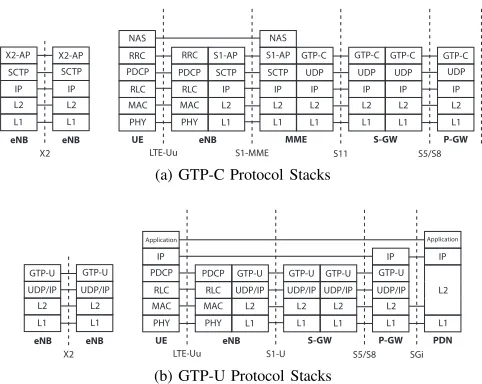
C. GTP Protocol
GTP (GPRS Tunnelling Protocol) is a group of protocols defined for QoS-specific traffic tunnelling between basestations and core network nodes (Fig. 2), seamlessly maintaining data and connections as UEs move between basestations. This approach maintains the same IP address for the UE regardless of its location, its mobility or the physical links/path between the UE and the internet gateway. We discuss the two main protocols: GTP-U for user traffic between the UE and the gateway, and GTP-C for control traffic to coordinate bearers and GTP tunnels (Fig. 3) between different core nodes, thus abstracting the physical nodes required to route the traffic. Dif-ferent bearers can have difDif-ferent QoS characteristics according to the different radio-specific settings applied to those bearers, where different QoS templates are available for selection when a bearer is setup or modified.
All control and data packets travelling through GTP tunnels are routed using TEIDs (Tunnel Endpoint IDs) which are unique identifiers within each mobile network. These TEIDs are generated and maintained using GTP-C messages. Fig. 2 shows the GTP protocol stacks for GTP-C and GTP-U packets. It is important to note that all user-plane traffic is encapsulated inside GTP-U packets. There are a variety of GTP-C control messages to control the tunnels in mobile core network, which usually come in Request/Response pairs. These GTP-C messages include: PHY MAC RLC PDCP RRC MAC PHY RLC PDCP L1 L2 IP
UE eNB P-GW
LTE-Uu S1-MME S11
S-GW NAS SCTP S1-AP RRC L2 L1 IP SCTP L1 L2 IP MME UDP GTP-C S1-AP NAS L2 L1 IP UDP L1 L2 IP UDP GTP-C GTP-C L1 L2 IP UDP GTP-C S5/S8 eNB L1 L2 IP SCTP X2-AP L1 L2 IP SCTP X2-AP X2 eNB
(a) GTP-C Protocol Stacks
PHY MAC RLC PDCP IP MAC PHY RLC PDCP L1 L2 UDP/IP
UE eNB PDN
LTE-Uu S1-U S5/S8
Application GTP-U L2 L1 UDP/IP GTP-U L1 L2 UDP/IP S-GW GTP-U L1 L2 IP SGi eNB L1 L2 UDP/IP GTP-U L1 L2 UDP/IP GTP-U X2 eNB P-GW L1 L2 UDP/IP GTP-U IP Application
[image:2.612.327.568.52.244.2](b) GTP-U Protocol Stacks
Fig. 2: LTE protocol stacks for control and data packets. The stacks show the data transmission on Uu, X2, S1, S11, S5/S8 and SGi. The protocol stacks for 3G are similar.
LTE Create/Delete Session Request/Response: Session con-trol messages are sent during attach/detach of the UE to/from the mobile network. They may also be sent when a UE switches between basestations that are served by different S-GWs. A Create Session Request sends the UE’s IMSI (a unique identifier for each UE), which can be later used to match TEIDs to individual UEs. Once a session is closed with a Delete Session pair, the TEIDs are released to use for a different tunnel (bearer).
LTE Create/Delete Bearer Request/Response: During each attachment at least one best-effort EPS bearer (default bearer) is created for each user. EPS bearers are created with Create Bearer messages pairs and closed with Delete Bearer pairs. Additional EPS bearers (best-effort or dedicated) may also be established as the UE demands, where these EPS bearers are identified by a 4-bit EBI (EPS Bearer ID). Each EPS bearer results in a different IP address to be assigned to the UE, so a UE may have more than one IP address if it uses more than one EPS bearer. These UE IP addresses are only used by the PDN-GW to route the user’s traffic in and out of the core network. All traffic to/from the UE IP address is tunnelled using GTP-U based on TEIDs.
3G Create/Delete PDP Context Request/Response: Data sessions in 3G are very similar to those in LTE, except tunnels are called ‘PDP Contexts’ and PDP Context ids are called NSAPIs. During 3G-LTE handovers EBIs are automatically translated to/from NSAPIs.
LTE Modify Bearer Request/Response: Whenever some aspect of a bearer is modified a pair of Modify Bearer messages are sent, for example as part of a handover between two cells in LTE which may or may not be controlled by the same MME, or as part of an LTE-3G handover, or when the QoS requirements for a bearer need to be changed.
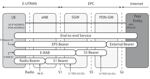
End-to-end Service
UE eNB SGW PDN-GW Peer
Entity
Radio S1 S5 Gi
Internet EPC
E-UTRAN
EPS Bearer External Bearer
E-RAB S5 Bearer
Radio Bearer S1 Bearer
EPS Bearer ID
E-RAB ID
S5 TEID (UL/DL) S1 TEID (UL/DL)
RB ID
APN (PDN ID) UE IP ADDRESS
[image:3.612.53.295.54.182.2](PDN ADDRESS)
Fig. 3: LTE Network Bearers
III. PROPOSEDMETHOD
The first and most important step to identify which core network traffic flows go through each basestation is to first identify the UEs that use the flows and so which user is using each GTP bearer. When a UE attaches to the network a default bearer is established that routes traffic for that UE through the network. Additional bearers with different QoS parameters may also be requested by the UE, where each new bearer will be identified by a different EBI/NSAPI. For each bearer a different IP address is assigned to the UE, so a single UE may have multiple IP addresses. These IP addresses persist through handovers and are only valid for the lifetime of the UE’s attachment to the network. These IP addresses can be used to identify the traffic generated by each UE. Further, it is possible to use GTP messages to identify which basestation is serving the UE at any point of time. It is important to note that as the UE moves throughout the network these TEID to IP address mappings must be updated.
Depending on whether the network is 3G or LTE the initial procedure is as follows: A new bearer is created using ‘Create PDP Context/Bearer Request/Response’ containing the IMSI, which identifies the subscriber associated with a bearer, and so identifies the UE. The TEIDs and IP addresses of intermediate nodes are also communicated during this procedure. From the outer IP packet carrying the GTP messages the ‘source’ IP addresses identify the eNodeB (LTE) or the RNC (3G), while the ‘destination’ IP address identifies PDN-GW (LTE) or GGSN (3G) which handles the traffic from UE. These IP addresses associate a basestation or gateway with given TEIDs.
A. 3G/GPRS Network
Activation Procedure: In 3G the only GTP message con-taining a unique identifier for a UE is ‘Create PDP Context’ where the IMSI of the UE is sent from SGSN to GGSN on the Gn interface as part of the attach procedure. The message contains the source TEID and IP address with which the GGSN may respond to the traffic coming from the SGSN. Until the SGSN receives the response, it can accept packets from the GGSN with the current TEID and IP address, but it can only start sending these packets when the uplink TEID and IP is received in a matching ‘Create PDP Context Response’. After that the default bearer is established and traffic may flow in both directions.
Intra-RNC handover: During handover, if the source and des-tination channels/cells/sectors are hosted by the same NodeB, or different NodeBs handled by the same RNC, the handover
is handled natively in the NodeB/RNC without changing any tunnel characteristics i.e.TEIDs and IP addresses remain the same.
Inter-RNC handover: When a handover requires changing to a different RNC, if the source and target RNCs are connected to the same GGSN an ‘Update PDP Context Re-quest/Response’ pair is sent on luPS with message elements containing the source and target TEIDs and GGSN IP ad-dresses. This information can be used further to associate GTP-C messages and PDUs to/from the UE on the target bearer. If the source and target GGSNs are different then the sessions needs to be completely closed using ‘Delete Session Request/Response’ on the luPS link. Depending on the type of handover (soft or hard) a ‘Create Session Request/Response’ is sent either before or after the old session is closed. These ‘Create Session’ messages are sent using the new TEIDs and IP addresses and also contains the UE’s IMSI so can be used to update its flows’ network addresses.
3G-LTE (Inter-RAT) handover: A UE may switch Radio Access Technology (RAT) from 3G to LTE if an LTE cell is in range or the coverage improves. Whenever a UE initiates such a handover, among other messages, a ‘Create Session Request/Response’ pair is sent on the S11 interface between the MME and target S-GW. It uses the same TEID and PDN IP addresses as the old session in 3G which can be used to associate the UE to the new session. The UE can also be recognized if the messages contains the IMSI and assigned IP address of the UE.
B. LTE Network
Activation Procedure: A ‘Create Bearer Request/Response’ is sent from the PDN-GW to the S-GW on S5/S8 interface and from the S-GW to the MME on the S11 interface as part of dedicated bearer activation procedure. Both messages contain the TEIDs and IP addresses for the S1-U and S5/S8 tunnels. Further, similar to 3G a ‘Create Session Request/Response’ is also sent as part of the activation procedure which contains the TEIDs and IP-addresses along with the UE’s IMSI.
Intra-eNodeB handover: LTE-LTE handover between chan-nels/cells hosted by the same eNodeB is handled natively by the eNodeB without any GTP messages.
Inter-eNodeB handover (X2 handover): If the eNodeBs are neighbours and are associated with the same MME then neighbouring eNodeBs can handle the handover natively using the X2 interface, and a ‘Modify Bearer Request/Response’ is sent over the S11 and S5/S8 which contains the TEIDs and IP addresses of the new bearer. Similar to 3G a ‘Create Session Request/Response’ message pair may also be sent on the same interfaces using the old TEIDs, which will contain the new TEIDs and IP addresses, and may also contain UE’s IMSI that helps identifying the UE. The old session then expires either before or after the new session is created depending on whether the handover is a soft or hard handover.
LTE-3G (Inter-RAT) handover The UE initiates an inter-RAT handover when the LTE coverage is no longer satisfactory due to either lack of equipment or congestion. As part of this handover ‘Modify Bearer Request/Response’ messages are sent on the S11 interface between the MME and the S-GW and on the S5/S8 interface between the S-GW and the PDN-GW. An ‘Update PDP Context Request/Response’ message pair can also be seen on the luPS interface, which uses the same TEIDs and IP addresses from the original LTE session.
C. Tracing Network Flows
Since it is now possible to track flows from all UEs the challenge is to determine which basestation is serving a UE at any point of time, and so bundle the UE traffic loads according to the basestations currently hosting those UEs. For LTE, this information can be obtained using the UDP PDU packets that carry the GTP messages. The source IP address of the UDP/IP header that represents the eNodeB that sends or receives the UDP packet is used so that the throughput of each eNodeB can be estimated without knowing the origin of the flows.
The situation is more complex in 3G. The source IP address no longer belongs to the NodeB but to the RNC which controls a set of NodeBs. Communication between an RNC and its child NodeBs are not seen in the core network. With this approach it is possible to estimate the load of each RNC but it is not possible to further partition this load for the NodeBs controlled by that RNC. Therefore, with 3G, it is not possible to rely only on GTP messages on the core network interfaces. However in any RAN OSS system there will be other readily available data sources to identify which basestation hosts which UE such as monitoring events from SGSN/MME, cells and UEs, which, when correlated with the GTP data. makes it possible to localise individual flows to particular NodeBs.
While data traffic is most likely to cause congestion in a basestation it is not the only traffic through the base-station. Other traffic includes voice call traffic, SMS traffic, and management traffic. This traffic is not transported using GTP. Therefore a challenge remains to trace and track this traffic, which currently remains a considerable but relatively deterministic traffic volume. However with relative growth in data traffic and the growth of VoLTE (Voice over LTE) and internet services as an alternative to traditional circuit switch voice communications, this proportion of the traffic that is not transported over GTP is rapidly decreasing.
IV. ANALYSIS OF AREALMOBILENETWORK
We used the method described in §III to analyse the GTP traffic from a real mobile network. We used a number of deep-packet inspection (DPI) probes to analyse GTP-C traffic on key interfaces in a segment of a medium-sized 3G/4G mobile network. Using the information from GTP headers, we were able to analyse the behaviour of user traffic in the network.
A. Experimental Setup
We used probes to collect GTP control messages over the S1 and X2 and equivalent 3G interfaces. For the purposes of this paper, the analysis was scoped to one hour of traffic collected between 20:00 and 21:00 local time, peak hour for data traffic. The traffic was collected on both 3G and LTE interfaces and was then classified by criteria such as UE, cell, and (e)NodeB
3G LTE
IMSIs 189638 390583
IP addresses 234787 479233
UTRAN/EUTRAN Cells 3830 1
Service Areas 18139 1
Routing Areas 23 1
Tracking Areas 1 1
[image:4.612.371.522.54.118.2]Location Areas 1 1
TABLE I: 3G & 4G nodes seen in Network Segment in 1 hour
Network Type Create Update Delete
3G 511589 53209 91047
[image:4.612.364.526.151.176.2]LTE 769329 19519365 747464
TABLE II: GTP-C messages seen in Network Segment in 1 hour
using our method. We then interpreted this information to analyse the network behaviour. In this section we present some statistics derived from that hour of inspected data.
B. Statistics and Results
Using information fromcreate sessionmessages, we evaluated the number of active users on the network. Further we used update session messages to track users in the network and in turn count the active cells as well as Service, Routing, Track-ing, and Location Areas. Table I summarises these statistics.
The number of create, update anddelete messages for 3G and LTE network are summarised in table II. We noticed that the number of LTE session messages are relatively larger than those of 3G, which is due to a much higher usage of LTE than 3G for data traffic with this operator. This can be confirmed by looking at the number of IMSIs and IP addresses that appeared in LTE GTP messages which are almost twice those in 3G.
0 5000 10000 15000 20000 25000 30000 35000 40000
0 2 4 6 8 10 12 14 16 18 20 22 24 26 28 30 32 34 36 38 40 42 44 46 48 50 52 54 56 58 60
# Messages
Minute
[image:4.612.327.560.434.598.2]3G Create Messages 3G Update Messages 3G Delete Messages 4G Create Messages 4G Update Messages/10 4G Delete Messages
Fig. 4: Message volumes seen in Network Segment in 1 hour
Fig. 4 illustrates the volume of GTP-C session messages observed over the one hour period examined.1 The number
of LTE update messages is a factor of 10 greater than 3G update messages because in LTE the eNodeB nodes and the SGW cooperate to perform many of the functions carried out between the RNC and NodeBs in 3G.
1The unusual drop in the number of LTE messages five minutes into the
NSAPI/EBI Value # of NSAPIs (3G) # of EBIs (LTE)
5 505398 722431
6 2215 35609
7 527 476
8 454 3
9 438
-10 421
-11 413
-12 376
-13 406
-14 375
-15 566
-TABLE III: Bearer Types for Created Sessions in 1 hour
We also observed the number of active 3G/LTE bearers for each bearer type during this observation period. In 3G, a Network (Layer) Service Access Point Identifier (NSAPI) identifies a PDP content. In LTE, a bearer is identified by an EPS Bearer Identifier (EBI). The NSAPI and EBI both have 4 bits, allowing a maximum of 16 PDP contexts / bearers to be established for each UE. The default bearer for each UE has a NSAPI/EBI value of 5.
These identifiers should not be confused with QoS Class Identifier (QCI), an integer from 1 to 9 that indicates differ-ent QoS performance characteristics for each IP packet. In particular, packets from bearers of different EBI/NSAPIs may have similar QCI values. As expected, majority of bearers in both 3G and LTE networks have the value 5 which indicates NSAPI/EBI value of the default bearer assigned to each UE as part of the network attach procedure. The other values appear when secondary bearers with a different QoS requirements are initiated. 99% of sessions in 3G have the default NSAPI value but in LTE, which has support for dedicated bearers for services like video that require different QoS characteristics, the number of sessions with the default EBI drops to 95%.
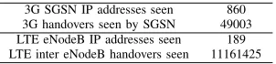
3G SGSN IP addresses seen 860
3G handovers seen by SGSN 49003
LTE eNodeB IP addresses seen 189
[image:5.612.79.271.53.151.2]LTE inter eNodeB handovers seen 11161425
TABLE IV: IP Addresses and Handovers Observed in 1 hour
We applied the approach described earlier to identify han-dovers in the network using GTP message data to identify the host cells and NodeBs of UEs, and in turn detect han-dovers each time UEs switch between different nodes. Table IV summaries the number of gateway nodes and handovers observed. The data represents only the number of nodes and handovers that appeared in the target network segment over this one hour observation period, so the actual number of nodes and handovers may be much higher than what we observed.
One can observe that the number of LTE handovers are much higher than 3G handovers. However, this does not imply that there are more LTE handovers in a mobile network than 3G handovers, but that mobility and LTE handovers is more visible in GTP messages than 3G, given that the majority of 3G handovers are intra-SGSN which would not produce control messages on the GTP control interfaces we monitored.
Observing how volumes of handovers change over time in a network can give a better realisation of network performance and even network saturation over time. Figure 5 illustrates volumes of 3G and LTE handovers over the observation period. We noticed a rapid increase in the number of handovers in LTE
400 600 800 1000 1200 1400 1600 1800 2000 2200 2400 2600
0 2 4 6 8 10 12 14 16 18 20 22 24 26 28 30 32 34 36 38 40 42 44 46 48 50 52 54 56 58 60
# Handovers
Minute
[image:5.612.326.558.54.221.2]3G inter SGSN Handovers 4G inter eNodeB Handovers / 100
Fig. 5: Observed 3G & LTE Handovers in 1 hour
as opposed to a more predictable descending behaviour for 3G. These differing trends may be explained by considering that the data is captured in the evening when there is less mobility and Inter-SGSN handovers are less likely to occur; we did not monitor the more localised intra-RNC handovers.
An analysis of handovers can produce valuable information about the status of the network. As an example, a sudden increase in the volume of handovers may suggest a disruption on the network. This can be further investigated by looking into the volume of inter-RAT handovers and comparing the numbers of 3G and LTE handovers.
While the information about handovers are useful, the deduc-tions highly depend on different characteristics of the observa-tion datae.g.which nodes and interfaces are monitored, which areas are involved, etc. As a simple example, if we narrow down the data to a certain cell by filtering only the basesta-tions/sectors involved, an increase in the volume of handovers compared to the other cells may suggest that a considerable number of UEs reside at the edge of that cell and are continu-ously ping-ponging between different basestations/sectors. So further decisions can be made to change antenna tilt angles, antenna power or inter-cell handover thresholds for those cells to provide better coverage for these areas. Using the same idea, an increase in inter-RAT handovers in a certain cell or basestation may suggest a local network issue e.g. weak reception, etc. which can be resolved by investigating the basestations involved or increasing the number of sectors for better reception.
V. OTHERAPPLICATIONS& RELATEDWORK
[image:5.612.101.252.433.468.2]all the nodes in the affected region.
When a basestation is operating close to its maximum capacity then delays and packet losses may be due to saturated radio channels. We can use this assumption to detect congested basestations. In order to estimate a basestation’s load it is first necessary to detect flows travelling in/out of it. An obvious n¨aive approach is to monitor all links in the network, however it makes sense to minimise the number of network probes required. We also propose a method to estimate the load on each basestation using only GTP protocol information. By analysing only GTP traffic it is possible to identify individual traffic flows between UEs and an internet gateway. When the traffic is associated with particular users and basestations, then standard traffic analysis can be used to identify transmission delay, packet loss, etc., and so infer if the basestation is suffering congestion. Specifically we can achieve this by monitoring the GTP traffic only on the S1, S11 and S5/S8 connections in LTE and equivalent links in 3G, as shown in Fig. 1.
An important application of using the proposed method is to detect corrupted links in the backhaul network. Using the aggregated flows for each node, one can estimate the current operating bandwidth of each basestation. If the basestation is operating below its capacity, given that inner core links are usually reliable (or if not reliable, this is easily detectable), any delay or packet loss suggests an issue on the link between the basestation and the core network. The operator can then narrow down the investigation to candidate links and fix them if required. In some networks many of these connections can be over microwave links sensitive to interference, or over links not directly controlled by the operator (e.g.on customer sites). As suggested in [2] information about handovers can be used to estimate the mobility of users, the population of UEs at each cell and even an approximate topology of the network at any given time. Further we can detect if a basestation is saturated by comparing its operating bandwidth to its capacity. Using this information mobile operators can decide to perform more targeted equipment upgrades in certain areas or by adding new sectors and/or basestations, adjust cell sizes, adjusting antenna tilt anglesetc. This information can also be used for balancing the load on basestations, S-GWs or even P-GWs without a need for expensive surveys or drive tests [3].
Real-time congestion detection is the key to successful congestion control. While decentralized methods like OWAMP suggested in [6] requires additional functionality on the nodes they also inject extra traffic to the channels which reduces the overall throughput of the network. Using the method proposed here enables congestion detection in real-time by inspecting the existing traffic traversing through different links without a need for extra equipment or traffic.
The accumulated bandwidth of each user can also be ob-tained from the summarized information of flows for each user. The network can use this information to calculate the bandwidth occupation percentage for each user which can be further used to establish resource allocation fairness.
Most other approaches for Core Network analysis (e.g.[5]) require the collection of measurements at each basestation. This either requires extensive probing or access to monitoring interface and performance data at each basestation, which in
turn requires significant infrastructure to gather and process this data. The need for EPC probing is also discussed in [4], where probing points are divided into categories depending on the method that is used and the information they provide. Our proposed method focuses on the interfaces and methods that are categorised as DPI probing in [4].
The approach in [2], which in some ways is similar to that presented here, collects summarized information for each network entity (e.g. user, sector, basestation site, group of sites etc.) by probing the inner core interfaces. However that approach suggests probing a long list of interfaces to capture almost every important control message traversing the network links. Our proposed method aims to minimize the number of probe points and limit them to S1-MME, S1-U, S11, S5/S8 (and possibly S4) in LTE and equivalent links in 3G.
VI. CONCLUSION
In this work we have discussed how user traffic is transported over modern mobile telecommunications network between UEs and the core network’s gateway to the public ‘internet’. Users’ data connections are maintained as tunnelled GTP bearers/contexts between the gateways and the basestations (or RNCs) hosting those users as they move around the network and switch between radio technologies. We demonstrate how to gather and maintain information about these individual flows, and as a result support various analytics tasks to monitor and understand the behaviour of the core network.We have shown that to analyse the network, it is not always necessary to collect data from all nodes and interfaces in the network, and a minimum set of interfaces is sufficient to collect enough information to perform significant analysis tasks.
ACKNOWLEDGMENT
This work was partly supported by Science Foundation Ireland under Grant No. 11/PI/1177.
REFERENCES
[1] 3GPP. 3rd generation partnership project; technical specification group services and system aspects; network architecure, 2014. TS-23002. [2] S.K. Kovvali, M. Vutukuru, C.W. Boyle, R. Ghai, J. Hutchins, T.
Abou-Assali, Y. Zhang, N. Rana, T.V.G. Araveti, R. Sirisikar, et al. RAN analytics, control and tuning via protocol, domain, and multi-RAT analysis, January 24 2013. US Patent App. 13/555,787.
[3] L.E. Li, Z.M. Mao, and J. Rexford. Toward software-defined cellular networks. In Software Defined Networking (EWSDN), 2012 European Workshop on, pages 7–12, Oct 2012.
[4] B. Wehbi, J. Sankala, and E.M. de Oca. Network monitoring challenges in the evolved packet core. In Future Network Mobile Summit (Fu-tureNetw), 2012, pages 1–8, July 2012.
[5] V. Yanover and Z. NUSS. Method and apparatus for load management in cellular communication networks, August 28 2014. US Patent App. 14/187,009.
![Fig. 1: Illustration of 2G/3G/LTE Mobile Core Network [1]](https://thumb-us.123doks.com/thumbv2/123dok_us/999928.614534/1.612.319.568.207.517/fig-illustration-g-g-lte-mobile-core-network.webp)