Design of Smart House System based on Webserver
Architecture Control
Dlnya Abdulahad Aziz
Computer Technical Engineering, AL-KITAB University, Iraq
ABSTRACT
The technological progresses fascinated the universe and gave a great opportunity to implement these progresses to design the smart house systems. This paper shows a unique design and implementation of a smart house system in a low cost. System automation is considered a great challenge especially outside the house. The proposed system controls and monitors house environment via specific webserver with respect to ESP8266 Node microcontroller anytime and anywhere remotely. The ESP works as a Wi-Fi station connected to the network through a router as an access point AP. The webserver based smart house system works under the supervision of the Net Pie website that shows the output results of the employed sensors identified by Temperature, Humidity, and Air quality. While, theses measurement can be demonstrated locally on a TFT LCD shield. In addition, the webserver allows the authorized user to turn house devices ON and OFF. Moreover, the system employs Arduino GSM shield to unveil system information intentionally as an SMS text. Finally, the GSM plays an important role with respect to the motion sensor and a camera affixed in a specific place in the house by applying triple control action such that when a motion is detected, the camera captures the events, the GSM sends an SMS to specific phone and the alarm system is turned ON accordingly.
Keywords
ESP8266 MCU systems, Smart House System, Control System Automation, GSM Based Motion Detector, Microcontroller Based Control Action.
1.
INTRODUCTION
The Smart House is the full controlled automated system designed efficiently to fit end user requirements. The technical progress all around the universe assigned the buildings and the houses to be equipped by Building Management System BMS that controls and monitors the electrical devices in various environments based on Internet of Things (IoT) approach. The electrical devices such as Air conditions, TVs, Ventilations, House Lights, and Irrigation systems etc., need to be controlled to guaranty security developments. The term BMS can be illustrated as the set of services and technologies that are offered to make the life easier [1]. Most of services like power systems, temperature – humidity control systems, lighting control systems, motion detection modules and etc. are included in BMS in order to enhance living style throughout the world. Smart house systems allow each device to be interacted with the sensors in a simple way. Furthermore, such systems offer entertainment, security, economy, etc. [2]. There exist several smart house systems that employed Bluetooth based android applications, Ethernet shields, GSM to control their systems. The most compatible and robust systems would be those which work under the supervision of Wi-Fi. The performance capability of the Wi-Fi is considered intelligent and perfect since the devices can be connected and coordinated in a simple way to reduce the costs. Smart house systems consist of monitors, sensors, microcontrollers and
different devices connected with each other via suitable protocol. The implemented idea helps to control house or building devices remotely. It is worth mentioning that the most effectible gadgets in such systems are the sensors and the display modules that show the information of the proposed environment by generating the output of the corresponding sensors. The sensors measure the environmental factors such as the temperature, humidity, air pressure, wind speed, air quality, etc. The benefits of the smart house technology are colossal and can be specified as follows [3, 4]:
1. Energy enhancement: The house lights and the devices can be controlled and monitored permanently such that the lights or the devices can be turned OFF depending on the proposed website. Hence, the electrical energy would be reserved efficiently.
2. Security enhancement: The system is monitored based on webpage monitoring system and the house can be surrounded by cameras to capture the events with respect to motion sensors. In addition, the smart house system can contain more features like fingerprints and key cards that maximize system security for a little bit more. 3. Accessibility: the voice commands can help the
incompetent persons to control house lights and the devices using their voice.
4. The convenience: The availability of control system designed to dominate house gadgets and simplify the life based on this system such that all appliances such as air conditions, TVs, multimedia players, etc. are controlled anytime throughout the house via appropriate measurement.
5. Life time: The efficiency and the life time are expanded due to the reasons presented above.
In this paper, a robust design of a low cost smart hose system is presented. The house is supervised using an ESP8266 Node MCU module that works under the domination of Wi-Fi connection methodology. In addition, the system can monitor the temperature, humidity, and the air quality in the house and can activate house's devices based on Net Pie website. Finally, the system is integrated by a GSM that triggers a camera affixed in a specific place to capture an event with respect to movement detection system.
2.
SMART SYSTEM COMPONENTS
The proposed system is constructed of several elements identified as follows:
2.1
Arduino UNO MCU
top of the board. This chip holds the programing code that intentionally activates each part in the board. To be more specific, Arduino microcontroller with the specification of each port is shown in Figure 1.
Fig 1: Arduino UNO Microcontroller
2.2
ESP8266 Node MCU
Arduino based ESP8266 Node MCU is a new microcontroller aspect that is created in corporation with Arduino Company. This microcontroller works somewhat according to Arduino microcontroller specifications regardless AVR processors [7] that lead the entire module to be compiled by Arduino IDE C++ compiler. The module is considered a complete kit due to the specification that was added the ESP board to reduce the individual sectors that needed to be attached to the board in order to perform specific roles. The new ESP MCU module was configured with respect to Arduino Uno board manager and SAM core. The term 'Core' was given to the group of software units that are needed to compile the Arduino C++ headers by using MCU language. The creativity of ESP8266 module leads to build robust and complete systems due to the design methodology that developed Arduino core under the domination of ESP8266 Wi – Fi based on GitHub ESP8266 core webpage. This module is learning software platform that combines between ESP8266 and NodeMCU firmware. The MCU module that is shown in Figure 2 works under the supervision of 802.11n and 802.11b networks. This means that it can serve as an Access Point AP, Wi – Fi station or both station and AP at the same time [8].
Fig 2: ESP8266 Node MCU Module
2.3
Temperature – Humidity Sensor
[image:2.595.317.538.300.399.2]The Temperature – Humidity sensor that is known by DHT11, reads and measures the temperature and humidity degrees in a single distinctive model. Temperature (T) and Humidity (H) Sensor are treated in a complex way with a calibration of digital signal output. The sensor guarantees extraordinary reliability and exceptional long term stability due to the private digital signal acquirement in the sensing technology. This module contains resistive humidity component and an NTC temperature component, connected to a high performance 8-bit microcontroller, offering excellent quality, fast response, anti-interference ability and cost effectiveness [9]. DHT sensor measures both (T) and (H) which hands the readings through ESP8266 module with respect to Net Pie website. The module is constructed of three terminals identified by Vcc, Data, and Gnd. The sensor acts well if linked with the digital pins of a microcontroller. As the schematic connection demonstrated in Figure 3, VCC pin must be provided by 5 V from ESP8266 MCU, the data is chosen to be connected to the digital pin D5 of ESP8266, and the Gnd terminal of the sensor is connected to the Gnd pin of ESP8266 board.
Fig 3: Temperature – Humidity (DHT11) Module
2.4
LPG Gas Sensor
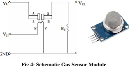
The Liquefied Petroleum Gas (LPG) is SnO2 based gas demonstrates slight conductivity in the clean air. The sensor module shown in Figure 4 states that the conductivity is directly proportional such that it gets higher in case of higher gas concentration. The sensitivity of MQ-2 sensor is considered exceptionally higher with propane, LPG, hydrogen, methane, and the other steams. Furthermore, the cost limitations of the module are appropriate for various applications [10, 11]. The sensor detects the presence of the flammable gas due to temperature elevation that is realized by the heating components inside the module. As a working principle, when gas leak is detected the conductivity of the sensor rises proportionally with gas concentration. The heater voltage VH supplies the working temperature to the sensor
while VC discovers the voltage over the load resistanceVRL.
Fig 4: Schematic Gas Sensor Module
The performance of the proposed sensor can be enhanced by employing an appropriate load resistance RL to satisfy the following equation:
PS=
Vc2∗ R S
[image:2.595.67.267.567.748.2] [image:2.595.322.537.601.711.2]Where,
PS: Sensitive power of the body.
Vc: Loop voltage.
RS: Sensing resistance.
RL: Load resistance.
The proposed LPG module can be used perfectly to discover gas leaks and to realize air quality as follows:
Gas Leak = Concetration ≤ Gas Spread ≤ 102 2
Air Quality = Gas leak − 1023 (3)
[image:3.595.318.539.74.189.2]Where, the value 1023 represents the maximum range of the analog read with respect to the mapping condition between the gas sensor and Node MCU module. The load resistance value does not make any sense to be conditionally restricted especially when the output voltage is intended to be computed with respect to the load resistance RL around the point at the output and the Gnd terminal as shown in Figure 5. On the other hand, the value of the load resistance is preferred to be chosen around 2 – 47 KΩ, meaning that the lower value offers less sensitivity, the higher value offers less accuracy.
Fig 5: Gas Sensor Interior Construction
Last but not least, the proposed sensor for 1000 ppm – LPG or butane concentration in the air can be calibrated by specifying the value of the load resistance RL = 20KΩ[10, 12].
2.5
Motion Sensor Module
[image:3.595.60.275.328.443.2]Motion sensor detects almost all motions particularly human motion in or out sensing range. The module was identified by PIR sensor, which is the abbreviation coming from "Passive Infrared" or "IR motion". The proposed sensor is considered inexpensive, easy to implement, small and consumes low power. Hereby, the sensor can be seen mostly employed in houses appliances and devices. Basically, PIR module is made of pyroelectric sensor, which detects the levels of the infrared radiations. Furthermore, the sensor is manufactured to be working in two separated halves. This creation methodology is performed because the sensor intends to detect the corresponding motion not only infrared radiation levels. It is worth mentioning that each half can terminate each other such that if low IR radiation is detected by one half, the output would flip high or low [13, 14]. The connection method between PIR sensor and the microcontroller is uncomplicated. The sensor works depending on the digital pins of the microcontroller such that the high voltage means (motion is detected) and the low voltage means (motion is not detected) with respect to the digital input. As shown in Figure 6, the sensor needs to be provided by 5V power from Arduino, the Gnd is connected to the Gnd of Arduino, and the signal terminal of the PIR is connected to one of the digital pins in Arduino microcontroller.
Fig 6: PIR Sensor Module
2.6
SIM900 – Arduino GSM Shield
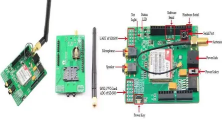
The GSM module is a communication device used to specify the route of the connection among different locations remotely. The term GSM is the abbreviation given to the global system for mobile communications, which is the international station that manages data transfer processes efficiently. The GSM unit employed in this work is SIM900 Arduino GSM shield that practically known as Quad – Band GSM / GPRS unit. The GSM module shown in Figure 7 offers several services such as Voice, SMS, Data, and Fax, knowing that each service is linked with a corresponding frequency specified by 850 MHz, 900 MHz, 1800 MHz, and 1900 MHz respectively [15, 16]. This module needs to be provided by 5 to 9 volt, classifying the whole unit as the most compatible modems with Arduino microcontroller. The symbol rate of the modem is specified by 9600 – 115200 bit per second. Hereby, it is intended to allocate the range of the communication topology over 900 MHz based on SMS service that makes data broadcasting through mobile phones more applicable.
Fig 7: SIM 900 Arduino GSM Module
2.7
TFT Touch Screen LCD Module
[image:3.595.316.539.414.535.2]Fig 8: TFT Touch Screen LCD Module
[image:4.595.319.542.261.408.2]For more details, it is intended to demonstrate pin out connection way as shown in Table 1.
Table 1. TFT LCD Pins Description Pin Name Category
LCD_RST
LCD Command Pins LCD_CS
LCD_RS
LCS_WR
LCD_RD
LCD_D0
LCD Data Pins LCD_D1
LCD_D2
LCD_D3
LCD_D4
LCD_D5
LCD_D6
LCD_D7
SD_SS
SD Card Data Pins SD_DI
SD_DO
SD_SCK
GND
Power Pins 5V
3.
THE WORKING PRINCIPLE
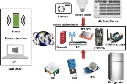
The system was designed to control each room in the houses in order to implement low cost smart house system methodology. The system can be separated in to two parts. The heart of the system that is constructed of the microcontrollers identified by Arduino Uno with GSM shield, ESP8266 Node MCU, router to be used as an access point AP and TFT LCD shield that is employed locally to display the information of the system. Whereas, the other part is the sensors and the devices that can be activated – deactivated remotely using web based control system identified by NET Pie. The employed sensors in the system are identified by Temperature – Humidity sensor DHT11, Motion detector PIR and gas detector LPG. The devices of the house shown in Figure 9 are identified by air conditioner, refrigerator, TV, and house lights knowing that the camera is activated with respect to PIR and Arduino GSM shield.
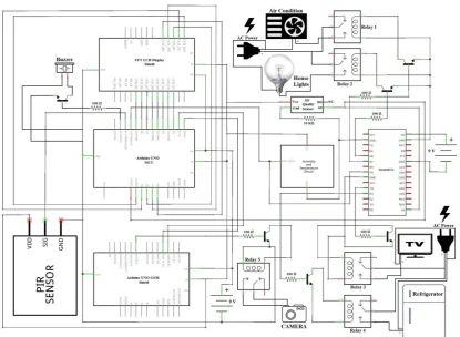
[image:4.595.47.286.267.622.2] [image:4.595.48.284.270.622.2]Fig 10: Overall System Connection
According to the devices and sensors that are presented before, the block diagram in Figure 9 shows the illustrative connection among the devices and the sensors by using the proposed microcontrollers. It is worth mentioning that the devices are controlled and the output results of the sensors are shown based on Net Pie login webpage shown in the following link:
https://netpie.io/login.
The user needs to be registered in the website using username and password to complete login processes. The next scene would be the output result of the sensors and the button based control action that activates home devices. The principle of the work starts when the sensors perform their corresponding jobs such that the Temperature – Humidity degrees are realized and the LPG sensor detects the quality of the air with respect to Eq. 2 & 3. As shown above in the schematic Fritizing software connection for the overall system in Figure 10, the proposed home devices that need to be provided by 220 V AC connected to the relays in order to fit the compatibility between the microcontroller that deals with only 5 V output voltage and the home devices.
The output of the sensors is demonstrated on Net Pie webpage as percentage gauges whereas the devices can be controlled through the buttons in the page that sends the signal through the internet with respect to the local IP of ESP8266 MCU module. As mentioned before, the ESP module can work separately as AP or Wi-Fi station or can work as both of them at the same time. Hereby, it can be stated based on this work methodology that the ESP works as Wi-Fi station. That is it routes the output of the sensors to the website and activates home devices by sending signal to the relays through the proposed website. Moreover, the PIR sensor is employed to protect an object that might be represented by a safe that contains valuable pieces. Hereby, a camera is affixed
stationary and oriented towards the safe. The motion sensor PIR is located wisely such that it covers the range of the motion. A tiny movement would cut the IR radiation and consequently the PIR will be activated. PIR sensor activation leads to apply triple impact control action where the fixed camera captures the event that changed the situation, the GSM module sends an SMS to a specific phone number declaring that a motion is detected and an alarm represented by a Buzzer will be flipped ON for a while as presented in the flowchart in Figure 11.
Fig 11: Programming Code as Flow Chart
[image:5.595.316.539.523.706.2]Fig 12: Smart House System Diagram
4.
RESULTS AND SIMULATIONS
[image:6.595.55.280.72.229.2]The results are realized with a help form Net pie website that created and managed the system to be shown tidy as shown in Figure 13. The unveiled results are the output reads of the sensors as percentage gauges at the left side and the devices controllers at the right side of the page.
Fig 13: The Results Based on Net Pie Webpage
[image:6.595.54.278.324.539.2]As mentioned before, the GSM module plays a great role to monitor system security with respect to motion sensor module. Since the availability of the network cannot be guaranteed everywhere, it was decided to modulate the programing code such that the sensor results can be received as an SMS to the phone number that requests the information by sending an SMS included by "weather" to the SIM number in the GSM module, while, the PIR status is sent automatically as shown in Figure 14.
Fig 14: SMS Contents in Reality
Finally, the overall output results of the sensors are simulated and shown sorted in Figure 15.
Fig 15: The Overall Sensors Results
5.
CONCLUSIONS
This paper demonstrates a unique and robust design of a low cost smart house system. The proposed system can work by the definition of Internet of Things (IoT) that automates environment devices efficiently. The creativity of the proposed smart house system allows monitoring and controlling the house based on webserver through ESP8266 node MCU module. For more clarity, the realized results are ordered as follows:
1. A novel design is proposed and implemented to control systems depending on webserver based control methodology.
2. The realized temperature, humidity and air quality results are shown as percentage gauge via webserver control site. 3. The system shows the realized results electronically
using the server and locally via the TFT LCD shield. 4. The devices of the house can be turned ON & OFF
anytime and anywhere with respect to network availability.
5. The GSM shield is employed to show environment information as an SMS in case of network absence. 6. The camera module is used to record the events that can
occur when a motion is detected in the location that is covered by PIR radiation range.
7. The proposed smart house system applies triple impact control action when a motion is detected such that the GSM sends an SMS to specific phone, the camera captures the events, and the alarm system is turned ON for a while.
8. The cost limitation of the design and the implementation is low due to the absolute dependency on the webserver control environment and the applicability of the local IP offered by the ESP8266 module.
6.
REFERENCES
[1] Aadel Howedi; Ali Jwaid;: "Design and implementation prototype of a smart house system at low cost and multi-functional" Future Technologies Conference (FTC), San Francisco CA USA, IEEE, pp: 876 - 884, 2016.
[2] Andi Adriansyah, Akhmad Wahyu Dan, “Design of Small Smart Home System Based on Arduino”, Electrical Power, Electronics, Communications, Controls, and Informatics Seminar (EECCIS), Malang, Indonesia, IEEE, pp:121 – 125, 2014.
[3] Adrian Florea, Iosif Băncioiu;: "Future house automation" 19th International Conference on System Theory, Control and Computing (ICSTCC), Cheile Gradistei, Romania, IEEE, pp: 699 - 704, 2015.
[image:6.595.64.271.659.752.2]Changsha China, IEEE, pp: 1017 - 1020, Volume: 3, 2010.
[5] Souveer Gunputh, Anshu Prakash Murdan, Vishwamitra Oree;: "Design and Implementation of a Low-Cost Arduino-Based Smart Home System" 9th IEEE International Conference on Communication Software and Networks, Guangzhou, China, IEEE, pp: 1491 – 1495, 2017.
[6] Yusuf Abdullahi Badamasi;: "The working principle of an Arduino" 11th International Conference on Electronics, Computer and Computation (ICECCO), Abuja, Nigeria, IEEE, pp: 1 – 4, 2014.
[7] Rampeesa Vijay, Thotakura Sainag, Vamsee Krishna A,: "Smart Home Wireless Automation Technology using Arduino based on IOT" IJECT Journal, Vol. 8, Issue 4, Oct - Dec 2017.
[8] Laurentius Kuncoro Probo Saputra, Yuan Lukito,: "Implementation of air conditioning control system using REST protocol based on NodeMCU ESP8266" International Conference, Smart Cities, Automation & Intelligent Computing Systems (ICON-SONICS), Yogyakarta, Indonesia, IEEE, pp. 126 – 130, 2017. [9] Pringgo W. Laksono, Wakhid A. Jauhari, Irwan Iftadi,:
"A system based on fuzzy logic approach to control humidity and temperature in fungus cultivation" International Conference, Electric Vehicular Technology and Industrial, Mechanical, Electrical and Chemical Engineering (ICEVT & IMECE), Surakarta, Indonesia, IEEE, pp.344 – 347, 2015.
[10] H. Abdul Hadi Nograles, Christopher Paolo D. Agbay, Ian Steven L. Flores, A. Linsangan Manuel, John Bethany C. Salonga,: "Low cost internet based wireless sensor network for air pollution monitoring using Zigbee module" Fourth International Conference on Digital Information and Communication Technology and its Applications (DICTAP), Bangkok, Thailand, IEEE, pp. 310 – 314, 2014.
[11] T. Machappa, M. Sasikala, M. V. N. Ambika Prasad,: "Design of Gas Sensor Setup and Study of Gas (LPG) Sensing Behavior of Conducting Polyaniline/Magnesium Chromate (MgCrO4) Composites" IEEE Sensors Journal, IEEE, pp. 807 – 813, Vol. 10, Issue. 4, 2010.
[12] Luay Fraiwan, Khaldon Lweesy, Aya Bani-Salma,: "A Wireless Home Safety Gas Leakage Detection System" Biomedical Engineering (MECBME), 1st Middle East Conference, Sharjah, United Arab Emirates, IEEE, pp. 11 – 14, 2011.
[13] Suresh S.; J. Bhavya; S. Sakshi; K. Varun; G. Debarshi,: "Home Monitoring and Security system" International Conference on ICT in Business Industry & Government (ICTBIG), Indore India, IEEE, pp: 1 – 5, 2016.
[14] Simarjit Singh Saini; Hemant Bhatia; Vatanjeet Singh; Ekambir Sidhu,: "Rochelle salt integrated PIR sensor arduino based intruder detection system (ABIDS)" International Conference on Control, Computing, Communication and Materials (ICCCCM), Allahbad India, IEEE, pp: 1 – 5, 2016.
[15] Hakan Üçgün, Zeynep K. Kaplan,: "Arduino Based Weather Forecasting Station" Computer Science and Engineering (UBMK), Antalya Turkey, IEEE, pp. 972 – 977, 2017.
[16] Tigor Hamonangan Nasution; Muhammad Anggia Muchtar; Ikhsan Siregar; Ulfi Andayani; Esra Christian; Emerson Pascawira Sinulingga,: "Electrical appliances control prototype by using GSM module and Arduino" 4th International Conference on Industrial Engineering and Applications (ICIEA), Nagoya Japan, IEEE, pp: 355 – 358, 2017.
ABOUT AUTHOR
Dlnya Abdulahad Aziz is currently B.Sc. student (Final Year) in Computer Technical Engineering at ALKITAB University, Iraq.